GOST 2.729-68 ESKD. Conditional graphic designations in schemes. Electrical measuring instruments
STATE STANDARD OF THE USSR
UNIFIED SYSTEM OF DESIGN DOCUMENTATION
CONDITIONAL GRAPHIC DESIGNATIONS IN SCHEMES
STATE STANDARD OF THE USSR UNION
Unified system of design documentation
CONDITIONAL GRAPHIC DESIGNATIONS IN SCHEMES.
Unified system for design documentation. Graphic identifications in schemes. Electromeasuring apparatus
This standard establishes symbolic graphic symbols of electrical measuring instruments on diagrams, performed manually or automatically, for products from all sectors of industry and construction.
(Introduced additionally, Amendment No. 1, 3).
Designations of electrical measuring instruments are given in the table.
1a. Sensor of measured non-electrical quantity
1. Electrical measuring device
c) integrating (for example, an electric energy meter)
1. If it is necessary to display non-standardized electrical measuring instruments, you should use combinations of the corresponding basic designations, for example, a combined indicating and recording device.
2. To indicate the purpose of an electrical measuring device, the conventional graphic symbols established in the ESKD standards are included in its designation. as well as letter designations of units of measurement or measured quantities, which are placed inside the graphic designation of an electrical measuring device
Source
What is resistance
Resistors have resistance, but what is resistance? Let's try to figure this out.
To answer this question, a plumbing analogy will help. Under the influence of gravity or under the influence of pump pressure, water rushes from a point of higher pressure to a point of lower pressure. Likewise, electric current under the influence of voltage flows from a point of higher potential to a point of lower potential.
What can interfere with the movement of water through pipes? The movement of water can be hampered by the condition of the pipes through which it flows. Pipes can be wide and clean, or they can be dirty and generally present a sad sight. In which case will the speed of water flow be greater? Naturally, water will flow faster if there is no resistance to its movement.
In the case of a clean pipeline, this will be the case; the water will have the least resistance and its speed will be practically unchanged. In a dirty pipe, the resistance to water flow will be significant, and accordingly the speed of water movement will not be very high.
Variable resistor.
Okay, now let's move from our plumbing model to the real world of electricity. Now it becomes clear that the speed of water in our realities is the current strength, measured in amperes. The resistance that the pipes provided to the water, in a real current-carrying system, will be the resistance of the wires, measured in ohms.
Like pipes, wires can resist current flow. Resistance directly depends on the material from which the wires are made. Therefore, it is no coincidence that wires are often made of copper, since copper has little resistance.
A resistor is a passive element of an electrical circuit that has a fixed or variable value of electrical resistance.
Other metals can offer very high resistance to electric current. So, for example, the resistivity (Ohm*mm²) of nichrome is 1.1 Ohm*mm². The magnitude of the resistance is easy to estimate by comparing it with copper, which has a resistivity of 0.0175 Ohm*mm².
When passing current through a material with high resistance, we can make sure that the current in the circuit will be less; it is enough to carry out simple measurements.
Variable resistance - purpose
Variable resistances are mainly used to adjust the volume in various household and professional radio equipment. We can say that they are designed to smoothly change voltage or current in various electrical circuits by changing their own resistance. For example, with their help you can smoothly adjust the brightness of an electric light bulb.
Symbol of a voltmeter device
STATE STANDARD OF THE USSR UNION
UNIFIED SYSTEM OF DESIGN DOCUMENTATION
CONDITIONAL GRAPHIC DESIGNATIONS IN SCHEMES
STATE STANDARD OF THE USSR UNION
Unified system of design documentation
CONDITIONAL GRAPHIC DESIGNATIONS IN SCHEMES.
Unified system for design documentation. Graphic identifications in schemes. Electromeasuring apparatus
This standard establishes symbolic graphic symbols of electrical measuring instruments on diagrams, performed manually or automatically, for products from all sectors of industry and construction.
(Introduced additionally, Amendment No. 1, 3).
Designations of electrical measuring instruments are given in the table.
1a. Sensor of measured non-electrical quantity
1. Electrical measuring device
c) integrating (for example, an electric energy meter)
1. If it is necessary to display non-standardized electrical measuring instruments, you should use combinations of the corresponding basic designations, for example, a combined indicating and recording device.
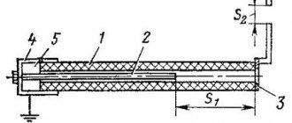
Application of potentiometers in pressure sensors
It is convenient to convert the operating parameters of various devices into electrical signals. A potentiometric liquid or gas pressure sensor is used in fuel supply systems in cars, gas supply systems in highways, etc. These are usually membrane measuring instruments.
Under the influence of the pressure difference on both sides of the membrane, it moves. At the same time, the slider also rotates. If the pressures P and Pi are equal to each other, the engine moves to the initial left position, at which the initial resistance of the device is established. As Ri decreases, the membrane moves to the right, and the slider sets the potentiometer brush to the position corresponding to the pressure difference.
To reduce the error in discrete changes in the resistance of the potentiometer, the number of turns on it is made at least 100. It can be completely eliminated by moving the brush along the axis of the calibrated wire of the rheochord.
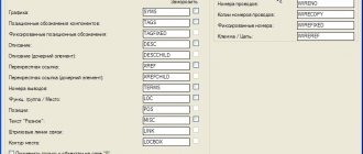
Electrical measuring instruments. GOST 2.729
Examples of designation of electrical measuring instruments. GOST 2.729
| № | Name | Designation |
| 1a. | Sensor of measured non-electrical quantity | |
| 1. | Electrical measuring device a) indicating | |
| Electrical measuring device b) recording | ||
| Electrical measuring device c) integrating (for example, electric energy meter) | ||
| Notes: 1. If it is necessary to depict non-standardized electrical measuring instruments, combinations of the corresponding basic symbols should be used, for example, a combined indicating and recording device. | ||
| Notes: 2. To indicate the purpose of an electrical measuring device, its designation includes the conventional graphic symbols established in the ESKD standards. as well as letter designations of units of measurement or measured quantities, which are placed inside the graphic designation of an electrical measuring device a) ammeter | A | |
| b) voltmeter | V | |
| c) double voltmeter | ||
| d) differential voltmeter | ||
| d) voltammeter | V.A. | |
| e) wattmeter | W | |
| g) summing wattmeter | ||
| h) varmeter (active power meter) | war | |
| i) microammeter | ||
| j) milliammeter | mA | |
| l) millivoltmeter | mV | |
| m) ohmmeter | ||
| n) megohmmeter | ||
| o) frequency meter | Hz | |
| n) wave meter | ||
| p) phase meter: measuring phase shift | ||
| p) phase meter: measuring power factor | ||
| c) ampere-hour meter | Ah | |
| t) watt-hour meter | Wh | |
| y) reactive volt-amp-hour meter | warh | |
| f) thermometer, pyrometer | t° | |
| x) polarity indicator | ± | |
| t) tachometer | n | |
| h) pressure meter | Pa | |
| w) liquid level meter | ||
| y) signal level meter | dB | |
| Notes: 3. It is allowed to enter the necessary data in the designations of electrical measuring instruments in accordance with the current standards for electrical measuring instruments. 4. If it is necessary to indicate the characteristics of the reading device of the device, then the following qualifying symbols are entered into its designation: a) a device whose moving part can deviate to one side from the zero mark: to the right | ||
| left | ||
| b) a device whose moving part can deviate in both directions from the zero mark | ||
| it is allowed to use the designation | ||
| c) vibration system device | ||
| d) a device with a digital readout | ||
| e) device with continuous recording (recording) | ||
| e) a device with point registration (recording) | ||
| g) printing device with digital registration | ||
| h) device with perforated registration | ||
| 2. | Galvanometer | |
| 3. | Synchronoscope | |
| 4. | Oscilloscope | |
| 5. | Oscilloscope | |
| 6. | Oscillographic galvanometer: a) current or voltage | |
| Oscillographic galvanometer: b) instantaneous power | ||
| 7. | Pulse counter | |
| 8. | Electrometer | |
| 9. | Semiconductor bolometer | |
| 10. | temperature sensor | |
| 10a. | Pressure meter | And |
| 11. | Thermoelectric converter: a) with non-contact heating | |
| Thermoelectric converter: with contact heating | ||
| 13. | Clock secondary | |
| Note. To indicate hours, minutes and seconds, use the following notation | ||
| 14. | Clock primary | |
| 15. | Clock with contact device | |
| 16. | The clock is synchronous, for example, at 50 Hz | |
| 17. | Maximum active power indicator with feedback from a wattmeter | |
| 18. | Differential voltmeter | |
| 19. | Solenometer | |
| 20. | Recording combined wattmeter and varmeter | |
| 21. | Time counter | |
| 22. | Watt-hour meter that measures energy transferred in one direction | |
| 23. | Watt-hour meter with maximum active power recording | |
| 24. | Distinctive symbol of the event counting function | |
| 25. | Electrical pulse counter with manual setting to n (set to zero at n=0) | |
| 26. | Electrical pulse counter with electrical zeroing | |
| 27. | Electrical impulse counter with several contacts; contacts close respectively on each unit (100), ten (101), hundred (102), thousand (103) events registered by the counting device | |
| 28. | A cam-controlled counting device that controls the closure of a contact every n events |
The material uses images of symbols from the Kit for drawing electrical circuits GOST Electro for Visio .
Comments
When drawing up power supply diagrams for premises, it is necessary to use signs for a number of devices, the functionality of which goes beyond the scope of the sets given in GOST. For some, traditional designations have analogues in GOST. For example, an electricity meter has a designation of type 4 lines in paragraph 1a on this page, or in paragraph 22. Modern multifunctional meters are also clearly designated as type 23, increasing the number of rectangles in the UGO and adding functions.
How to correctly designate devices such as power limiters (for example, OM-310), electric motor control devices, etc., which have several types of sensors (for example, they record the voltages of three phases plus measure three currents using three current transformers plus they measure the zero-sequence current with a separate differential current transformer plus they accept several potential commands plus they are controlled via the RS-485 interface) ? And the number of functions performed and such devices is large - shutdown when power is exceeded, and when currents are exceeded by phase or total, and protective shutdown when phase voltages go beyond the tolerance or when the phase vector diagram is violated, and separate control of priority and non-priority loads, and indication, not only of the main parameter, but also of two or three dozen more network and load indicators? And in GOST 2.710 there is not even a remotely suitable designation for such a conglomerate.
Is the only way out to just draw an empty rectangle and call it “A” that doesn’t mean anything in particular? Or draw a larger rectangle and write all the necessary information inside in plain English (for example, list the functions involved and indicate the required settings)?
Source
Practical lesson. Symbols on the device, basic parameters of voltmeters.
Practical lesson.
Symbols on the device, basic parameters of voltmeters.
The Italian scientist Alessandro Volta, after conducting a series of experiments with electricity, comes to the conclusion that electric current can be obtained by combining metals with liquid. By placing copper plates coated with zinc in acid, in 1800 he created the first electrochemical energy source, later called the “voltaic column”.
He also establishes that when two different metals are joined, a force is generated, which is expended in the work of moving an electric charge from one point to another. In this case, the displaced charge changes its potential (the amount of energy) it possesses. The difference between the initial potential and the final potential is called “voltage”.
To measure the amount of electricity, Volt uses a metal rod inserted into a rubber stopper and placed in a bottle. He puts straws on the lower end, located in the bottle, and a ball on the other. The scientist observes that when the ball comes into contact with an electrified substance, the straws repel. This allows him to judge the degree of charge of the material.
Volt proved the existence of voltage by conducting the following experiment. A copper and zinc disk was placed on the electroscope (a device that records charge). A thin layer of dielectric is laid between them. For a short time, the physicist connected the metals together with a wire. The petals on the electroscope moved slightly apart. Next, the disks moved apart to a greater distance, while the recorder petals diverged even more.
In fact, this was the first experiment to measure, albeit in rough form, voltage. In 1830, the English scientist Michael Faraday discovered the phenomenon of electromagnetic induction, which was subsequently used to create a number of electrical measuring instruments.
In 1881, French physicist Arsene D'Arsonval created a device consisting of a coil and a pointer placed in a constant magnetic field. Electric current was supplied to the coil, causing the needle to deviate from its initial position. In the same year, the International Electrotechnical Congress was held, at which the designations of electrical quantities were adopted. The device designed to measure potential differences was called a voltmeter, and voltage began to be measured in volts.
ESSENCE OF THE DEVICE
Voltmeter
is a device belonging to the class of electrical measuring instruments, designed to measure electromotive force (EMF) on a section of an electrical line. In other words, a voltmeter shows the potential difference (voltage) between two points in an electrical circuit. It is always connected in parallel to the current source or load.
When measuring, the device should not in any way affect the parameters of the electrical circuit, therefore a device with an infinitely large internal resistance is considered ideal. The accuracy of measurements primarily depends on this parameter. Depending on the shape of the measured signal, voltmeters are divided into devices that measure direct or alternating t
Let's move on to the test voltage classes: this is the voltage that the insulation of a given device can withstand. If measured in kV - kilovolts, i.e. thousand volts, the value is indicated inside the asterisk.
Rice. Symbols of test voltage classes
You need to pay attention to the symbols below when it comes to the type of current or voltage: whether they are constant or variable. For example, magnetoelectric
The device measures constant quantities.
If these instruments measure alternating current, the needle will begin to tremble near the zero scale reading. Electromagnetic
instruments can measure both constant and variable quantities.
Ferrodynamic
devices are less accurate, but they are simple and can be used in switchboards located in places with increased shaking and vibration.
Induction
devices were used during Soviet times as electricity meters.
Electrostatic
devices have the highest accuracy classes (0.005) and are available for voltages in millivolts and kilovolts.
Conclusion:
Practical lesson No. 3.
Main types of voltmeters and their brief technical characteristics.
According to the measurement principle, voltmeters are:
· Diode-compensation. The principle of their operation is based on comparison of the measured signal with a reference signal produced by a controlled source. The main design element is a vacuum diode. They are used only to measure a harmonic (alternating) signal, but over a wide frequency range. The measurement accuracy is quite high.
· Pulse. The amplitude value of the signal of periodic and single pulses with a large duty cycle is measured. The block diagram of the device consists of a pulse level converter, an amplifier and a reading device.
· Phase sensitive. A characteristic feature of such a device is the presence of two indicators that serve to register the real and imaginary components of the complex signal. They are used to study amplitude-phase characteristics.
· Selective. Their circuit design is similar to superheterodyne radio receivers. Capable of identifying signal harmonics and measuring their rms amplitude.
· Universal. Multifunctional devices that can measure any type of signal.
All of the above devices are used in laboratories and in production to set up the operation of certain equipment. In everyday life and amateur radio, voltmeters that can measure the rms voltage of alternating and direct current are more often used. Therefore, all types of devices are usually divided into two types: analog and digital.
DESIGNATION AND CHARACTERISTICS
According to the unified system of design documentation, on circuit and electrical diagrams a voltmeter is usually designated as a circle, in the middle of which the Latin letter V fits. In pictures and drawings, the device is signed with the Russian letter “V” or the English abbreviation PV.
In addition, the first digit in the name of the device after the letter “B”, produced in the countries of the former USSR, indicates the type of device. For example, "B2" - direct current, "B3" - alternating current, "B4" - pulsed, "B7" - universal.
To evaluate the capabilities of the device, it is customary to use the following technical characteristics:
Internal source impedance. Characterized by the resistance measured at the output of the device. The higher this value, the higher quality the device is considered.
· Measuring range. This is the area limited by the smallest and largest value that the device can measure. Most testers are universal, measuring voltage in the range from tens of millivolts to kilovolts. However, research centers use instruments that can determine miles or even microvolts.
· Accuracy of readings. This parameter indicates the error between the actual voltage values and the measured ones. Depending on the values of the measured signal amplitude, this error changes, therefore it is characterized by an accuracy class. For example, for a device operating in the measurement range from 0 to 60 volts, an accuracy class of one will mean that the device error cannot exceed 0.6 V, but at small values such a tolerance is unacceptable. Therefore, the measurement range is divided into small sections.
· Frequency range. It is determined by the sensitivity of electronic components to register a signal of a particular frequency.
· Operating ambient temperature. Indicates the conditions under which the measurement error will correspond to the declared accuracy class.
TYPES OF VOLTMETERS
In addition to the technical parameters that determine the purpose of the device, descriptions of a voltmeter often indicate its physical dimensions. This is due to the fact that all devices according to their design are divided into three types:
1. Portable.
2. Stationary.
3. Panel (panel).
The former usually refer to semi-professional and amateur measuring devices. They look like rectangular boxes made of hard plastic or carbolite. All of them operate from mobile power sources, rechargeable batteries or batteries. For the convenience of determining the amplitude value of the signal, the set with voltmeters includes a removable pair of probes.
The latter are powered from an alternating voltage network through a built-in power supply. Most often these are highly specialized testers with high measurement accuracy. They are used in the professional field to control voltage at important points in the electrical circuit.
The third type is intended for use in specially equipped cabinets for constant monitoring of voltage levels. Usually used in conjunction with protective devices. This type of voltmeter measures alternating single-phase or three-phase voltage.
ANALOG DEVICE
A distinctive feature of an analog device is the presence of a dial indicator. The operating principle of this type of voltmeter is based on the use of a measuring head. Structurally, it is made in the form of an aluminum circuit placed in a magnetic field. The arrow of the device and the axis are glued to the frame on which the wire is wound.
Through springs or stretch marks that hold the arrow in the initial position, current is supplied to the structure. Depending on the magnitude of its strength, the magnetic field affects the frame with different intensities. As a result, a torque arises that removes the arrow from the zero state.
Dampers are used to ensure a stable pointer position. Below the pointer there is a scale calibrated according to standard instruments. Therefore, each arrow position corresponds to its own voltage value. As soon as the measurements are completed, the current stops flowing to the measuring head and the pointer, under the action of the stretch marks, returns to its original position.
The block diagram of an analog device can be substituted in the form of a sequential chain consisting of an input device, a current amplifier, a detector, and a measuring head.
The technical capabilities of a voltmeter are largely determined by the sensitivity of the head. The advantages of an analog device include inertia and immunity to interference. It is ideal for displaying signal dynamics. Such a meter instantly shows the change in voltage. For example, when calculating voltage with ripple, the tester, integrating them, shows the average value. You can expand the measurement range by using additional resistances or shunts. But despite their advantages, pointer voltmeters are characterized by large errors and difficulty in interpreting measurement results.
Conclusion:
Practical lesson No. 4.
Voltmeter device.
Purpose of the work: to get acquainted with methods
of measuring voltage with a voltmeter.
Work order:
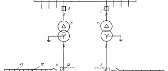
Electronic analog voltmeters are the first example of electronic measuring instruments covered in the course. Among them there are both direct conversion voltmeters and comparison voltmeters. Let's consider the operating principle, block diagrams and main functional units of analog voltmeters for direct conversion and comparison.
ANALOG DIRECT CONVERSION VOLTMETERS
As can be seen from Fig. 1, in the most general case it includes an input device (ID), the input of which is supplied with the measured voltage Ux, a power source and a magnetoelectric device used as an IU.
In the simplest case, the input device is a divider of the measured voltage - an attenuator, with the help of which the measurement limits of the voltmeter are expanded. In addition to accurately dividing Ux, the VU should not reduce the input impedance of the voltmeter, which affects, as has been repeatedly emphasized, the methodological error in measuring Ux. Thus, the use of the VU in the form of an attenuator is, in addition to additional
R and s.1. Generalized block diagram of a direct conversion analog voltmeter.
resistances and measuring voltage transformers, another way to expand the measurement limits of voltmeters. It is this method that is used in electronic voltmeters and other radio measuring instruments.
A direct current amplifier (DCA) is used as an IP in DC voltmeters (B2), and a detector is used in AC and pulsed current voltmeters (VZ and V4) in combination with a DCPA or an AC amplifier. Converters in other types of voltmeters have a more complex structure. In particular, selective voltmeter converters (B6) must provide, in addition to signal detection and amplification, its frequency selection, and phase-sensitive voltmeter converters (B5) must provide the ability to measure not only the amplitude, but also the phase parameters of the signal under study.
The block diagram of an analog DC voltmeter corresponds to the generalized diagram in Fig. 1. The main functional unit of such voltmeters is the UPT. Modern DC voltmeters are designed primarily as digital instruments.
Depending on the purpose, AC and pulse current voltmeters can be designed according to one of two block diagrams (Fig. 2), differing in the type of power supply. In voltmeters of the first modification (Fig. 2, a), the measured voltage Ux^ is converted into a constant voltage Ux=, which is then measured by a direct current voltmeter. On the contrary, in voltmeters of the second modification (Fig. 3.14, b), the measured voltage is first amplified using an AC amplifier, and then detected and measured. If necessary, a UPT can be additionally connected between the detector and the DUT.
By comparing the block diagrams of Fig. 2, it is possible, even before considering the circuit solutions of their functional units, to draw certain conclusions regarding the properties of voltmeters of both modifications. In particular, voltmeters of the first modification do not have the same restrictions regarding the frequency range of measured voltages as voltmeters of the second modification, where this parameter depends on the bandwidth of the AC amplifier. But voltmeters of the second modification have high sensitivity. From the course “Amplification Devices” it is known that with the help of an alternating current amplifier it is possible to obtain a significantly higher gain than with the help of a UPT, that is, to design microvoltmeters with a lower limit Ux^. limited by the amplifier's own noise. Due to change
Fig.2. Block diagrams of analog voltmeters for alternating and pulsed current:
a—with a detector at the entrance; b - with an AC amplifier at the input.
the division factor of the power supply and the gain of the amplifiers, the range of measured voltages can be large for voltmeters of both modifications.
Detector type in block diagrams Fig. 2 determines whether voltmeters of both modifications belong to amplitude, root-mean-square or medium-rectified voltage voltmeters. In this case, pulse current voltmeters (B4) are designed only as voltmeters of the first modification in order to avoid distortion of the pulse shape in the alternating current amplifier. When measuring the voltage of single and rarely repeating pulses, either diode-capacitive pulse expanders in combination with detectors or amplitude-time pulse conversion, characteristic of digital voltmeters, are used.
Let us now consider a typical block diagram of selective voltmeters, which are used in measuring small harmonic voltages under interference conditions, in studying the spectra of periodic signals, and in a number of other cases. As can be seen from Fig. 3, the voltmeter is essentially a superheterodyne receiver, the principle of operation of which is explained in the course “Radio Engineering Circuits and Signals”.
Frequency selection of the input signal is carried out using a tunable local oscillator, a mixer (CM) and a narrow-band intermediate frequency amplifier (IFA), which provides high sensitivity and the required selectivity. If selectivity is insufficient, double and sometimes triple frequency conversion can be applied. In addition, selective voltmeters must have an automatic frequency control system and a calibrator. A calibrator is an exemplary source (generator) of alternating voltage of a certain level, which makes it possible to exclude systematic errors due to changes in the local oscillator voltage when it is adjusted, changes in the transfer coefficients of the voltmeter components, the influence of external factors, etc. The voltmeter is calibrated before measurement when setting the P switch from position 1 to position 2.
Rice. 3. Block diagram of a selective voltmeter.
In conclusion, we note that in one device it is not difficult to combine the functions of measuring direct and alternating voltages, and with the help of additional functional units and corresponding switchings (by analogy with rectifier devices) to form combined devices called universal voltmeters (B7). Modern types of such voltmeters, as a rule, are designed as digital devices, which makes it possible to further expand their functionality and increase accuracy. In this regard, the features of constructing block diagrams of universal voltmeters will be considered in the works of colleagues.
ANALOG VOLTMETERS COMPARISON
Rice. 4. Measuring potentiometer circuit.
Electronic analog comparison voltmeters for the most part implement the most common modification of the comparison method - the zero method. Therefore, they are more often called compensation voltmeters. Compared to direct conversion voltmeters, these are more complex, but also, as previously emphasized, more accurate instruments. At the moment of compensation DХ = 0 and the device does not consume power from source X. In relation to compensation voltmeters, this means the ability to measure not only voltage, but also the EMF of low-power sources. In the practice of electrical and radio measurements, such measurements are carried out using both electronic compensation voltmeters and electromechanical ones. To explain the use of the zero method when measuring EMF and voltage, let us first consider the classical circuit of an electromechanical DC compensator, shown in Fig. 4.
One of the main functional units of any compensator is a high-precision variable resistor R, on the scale of which the measured value of the emf (Ex) or voltage (Ux) is measured. Therefore, compensators are usually called measuring potentiometers according to GOST 9245-79. As an exemplary measure of EMF, a normal element (NE) is used - an electrochemical source, the EMF (Ea) of which is known with a very high degree of accuracy. However, the capacity of the NE is small, and long-term comparison during measurements of Ex(Ux) with En is impossible. Therefore, the potentiometer circuit is supplemented with an auxiliary source of EMF (Eo) of large capacity. For comparison with Ex(Ux), the voltage drop across the standard resistor Rн is used, created by the current from the source Eо - the operating current (Iр), which is pre-set. Thus, the Ex{Ux) measurement process must consist of two stages.
At the first stage, the required value of Ip is established. To do this, set the switch to position 1 and use the potentiometer Rp to achieve a zero reading of the indicator I (usually a magnetoelectric galvanometer). As can be seen from Fig. 4, this corresponds to IpRн=En, i.e. the operating current Iр, which must then remain constant, will reproduce the value En during the measurement process.
At the second stage, the Ex(Ux) value is measured. To do this, the switch is moved to position 2, and by changing the resistance of the potentiometer R, a zero reading of I is again achieved. With Iр = const, this corresponds to Ex (Ux) = IpR, i.e., the desired value Ex(U^}^.R and can be counted on the R scale.
Thus, the metrological characteristics of DC measuring potentiometers are determined by the parameters of the NE, standard resistors, indicator and source Ey. Saturated and unsaturated reversible galvanic cells are used as NEs, the positive electrode of which is formed by mercury, and the negative electrode by cadmium amalgam. NE accuracy classes are regulated by GOST 1954-82 within the range of 0.0002...0.02 and determine the accuracy class of the potentiometer as a whole. The potentiometer R is made according to a special circuit that ensures the constancy of /p when R changes and the required number of signs (decades) when counting Ex(Ux). These requirements are met by circuits with replacement and shunt decades.
Measuring potentiometers can also be used to measure alternating voltages. However, in this case the compensating voltage must be adjusted not only in magnitude, but also in phase. Therefore, such potentiometers have a more complex circuit than DC potentiometers, and are significantly inferior in accuracy to them due to the lack of a standard measure for alternating current, similar in its characteristics to the NE. In the practice of electrical and radio measurements, they are completely replaced by electronic compensation voltmeters.
In compensation voltmeters, the measured voltage (DC, AC, pulse) is compared with the DC compensation voltage, which in turn is accurately measured by a DC voltmeter and is a measure of Ux. A typical block diagram of such a voltmeter is shown in Fig. 5.
As can be seen from Fig. 5, the basis of the voltmeter is a compensation power supply, consisting of a measuring diode V with a load R, an adjustable source of constant compensating voltage -Ek, an amplifier and an indicator with two stable states. In the absence of Ux, the indicator implemented using
functional nodes are in the first stable state, and at a certain threshold value they go into the second state. The process of measuring Ux comes down to a gradual increase in Ek until the indicator goes into the second stable state. The value Ek corresponding to the moment of transition is measured by a DC voltmeter and is a measure of Ux.
Rice. 5. Block diagram of a compensation voltmeter.
In combination with other circuit solutions (use of an indicator with a low threshold voltage, a tube measuring diode with a stable characteristic, etc.), it becomes possible to design high-precision compensation voltmeters.
The disadvantage of the considered scheme is the need to install it manually. Therefore, in most voltmeters the power supply circuit is complicated, providing automatic compensation for Ux and Ek. Autocompensation voltmeters are direct-indicating devices and are more convenient to use.
MAIN UNITS OF ANALOG VOLTMETERS
Let's consider the circuit designs of the main functional units that determine the metrological characteristics of analog voltmeters. Most of these components are also used in other types of electronic measuring instruments.
Input device
As mentioned above, the VU is intended to expand the measurement limits of the voltmeter. In the simplest case, it is an attenuator made using resistive (Fig. 6, a), capacitive (Fig. 6, b) or combined (Fig. 3.18, c) circuits.
The simplest and most universal (for Uх= and Ux~) is the circuit shown in Fig. 6a, but at high frequencies parasitic capacitances begin to have a significant effect. Therefore, at high frequencies they switch to either a capacitive circuit or a combined one, which at R1C1 = R2C2 turns out to be frequency-compensated (division coefficient k = R2/(R1 + P2), as for the circuit shown in Fig. 6, a).
Fulfilling the remaining requirements and, above all, ensuring a high input resistance and minimal input capacitance of the voltmeter leads in some cases to a more complex structure of the voltmeter. The most universal and often used in modern AC voltmeters is the VU, the block diagram of which is shown in Fig. 7.
The fundamental feature of this circuit is the change in Uv using a low-resistance resistive attenuator with constant input and output impedance. This increases the accuracy of the Ux~ measurement, but requires the introduction of an impedance converter (PI) into the structure of the VU, which ensures the transformation of the high input resistance of the voltmeter into the low input resistance of the attenuator. A voltage follower based on a field-effect transistor with deep negative feedback is most often used as a PI. Using an input divider
Rice. 6. Voltmeter attenuator circuits:
a—on resistors; b - on capacitors; c - combined.
Rice. 7. Block diagram of a universal input device.
voltage (VDN) provides an additional possibility of expanding the measurement limits of the voltmeter. The VDN is a fixed resistive-capacitive divider (see Fig. 6, c)
At high frequencies, the input resistance of the voltmeter decreases, and the input capacitance and inductance of the conductors form a series oscillating circuit, which at the resonant frequency has practically zero resistance. To neutralize these effects, the PI is structurally designed as a remote probe with a VDN in the form of a nozzle.
Conclusion: