In the previous lesson - “Making connections on diagrams” we learned how to connect elements on diagrams - draw wires. Now let's look at other elements of wire connections and start with wire numbering.
Quite often on electrical diagrams there is a numbering of wires or, more correctly, circuits. Some people use it, and some don’t, but that’s not what we’re talking about now. The main thing is that in AutoCAD Electrical you can automatically number wires, both for an individual wire and for a separate drawing or for the project as a whole. In this case, you can display this numbering, or you can hide it by hiding the corresponding layer of the drawing.
Wire numbering types and wire number layers
The wire number is an attribute included in a hidden block that does not have a graphical representation. When you insert a wire number, this hidden block is inserted into the wire, and the attribute value, essentially the wire number, is displayed next to it. The display location is determined by the settings of the selected wire number placement style. Each circuit in the project is assigned a single wire number.
There are four types of wire numbers:
- Normal – updated every time the automatic wire numbering command is executed;
- Fixed – is not updated when the automatic wire numbering command is executed; it has a fixed value that can be changed manually.
- Additional - is a copy of the regular or fixed wire number assigned to the selected circuit. A chain can have only one regular or fixed number and several copies of it, which can be located in different parts of the chain.
- Terminal/circuit – used for numbering terminals and signal arrows.
Depending on the type of number, the wires are placed in different layers. But if desired, they can be placed on one layer. Layers for different types of wire numbers are defined initially in Project Properties and are inherited or modified, if necessary, in Drawing Properties .
On the Drawing Format , under Layers, click the Set .
In the Define Layers the Wire Number Layers section lists the layer names for the different wire types.
Don't use one layer for different types of wire numbers, let them be different layers, each with its own color.
Ground wire color
By modern standards, the ground conductor is yellow-green. It usually looks like yellow insulation with one or two longitudinal bright green stripes. But there are also transverse yellow-green stripes in color.
Grounding may be this color
In some cases, the cable may only have yellow or bright green conductors. In this case, the “earth” has exactly this color. It is displayed in the same colors on diagrams - most often bright green, but it can also be yellow. Signed on diagrams or on ground equipment in Latin (English) letters PE . The contacts to which the “ground” wire must be connected are also marked.
Sometimes professionals call the grounding wire “neutral protective”, but do not be confused. This is an earthen one, and it is protective because it reduces the risk of electric shock.
Location of wire numbers
Wire numbers can be located:
- above the wires (on the left for vertical wires);
- under the wires (on the right for vertical wires);
- in line with the wire;
- on the leader.
Setting the location of the wire number is carried out in the Project Properties or in the Drawing Properties in the Wire Numbers .
When choosing to place wire numbers on the connection line, you must specify the gap between the number and the ends of the wires where the number is inserted. After clicking the Configure breaks... , the Configure breaks for wire labels on connection lines window opens . This window indicates the required dimensions.
When changing the location of wire numbers in the drawing properties, the location of existing numbers does not change. To change them, you need to delete existing wire numbers and add them again.
AutoCAD Electrical creates a leader with the wire number if the wire number overlaps with any circuit elements. The leader itself does not check for overlap with other objects. The check for whether leader placement is required is triggered when inserting wire numbers, as well as when moving a wire number.
If the program cannot find a suitable place to place the wire number, it must be done manually.
If possible, avoid using wire number callouts. To do this, in the Project Properties or in the Drawing Properties, Wire Numbers tab, in the Leaders field : specify Never .
Adding wire numbers and wire number callouts
AutoCAD Electrical allows you to automatically add wire numbers for each circuit in your design. Callouts can also be automatically added, both for each wire number, and only for those numbers for which there is not enough space to be placed without a callout.
Circuits are processed from left to right and from top to bottom. By default, the numbers are centered on the first chain segment found. But the user can specify an offset from the left end (for wires running horizontally) or from the top end (for wires running vertically).
By default, only one wire number is placed for each circuit. If necessary, the user can add as many copies of the wire number as he wants in different parts of the circuit.
If there are too many graphics in the default number locations, a wire number callout is added (unless callouts are not disabled).
What colors are in electrical wiring?
According to the rules of electrical installations (PUE), electrical wiring is covered with insulating material of different colors.
This makes the elements easier to recognize by the master. The work uses a three-core cable, where there is a phase, zero, ground, which are colored differently. Previously, there was only black and white execution, but with the introduction of new rules, it has become safer and easier. There are options:
- white;
- black;
- red;
- cyan (blue);
- yellow-green;
- brown.
Ground wire color
Yellow-green – “grounding” elements. Sometimes the owner of the device comes across simply yellow or green, with two letters - “RE”, which are responsible for marking “ground”. If the grounding element is together with the neutral element, it is designated “PEN” and often has a green-yellow tint.
What is the phase designated by?
Contact with the phase is the most dangerous.
You should be careful when carrying out work. Since some cases can even be fatal, manufacturers mark it with a bright color to avoid confusion with other variants. Red and black are the colors of the phase. There are also others:
- brown;
- lilac;
- orange;
- pink;
- violet;
- white;
- grey.
It will be easier to deal with a bunch of batteries when zero and ground are eliminated. The phase in the diagram is marked with the letter L. If there are several phases in the network, which is often the case at 380 V, such wires are designated L1, L2, L3. In other cases, they may be designated: the first phase is A, the second is B, etc.
Neutral wire in a single-phase network
Presented in blue or cyan shades. In electrical engineering there is no other designation for this color. It doesn’t matter which cable is used in the work - three-core, five-core, the color is the same.
The grounding and neutral conductors may differ in cable thickness. In diagrams, “zero” is signed with the letter N. Such a cable is classified as a working element, because, unlike grounding, it takes part in creating the power supply circuit. In some circuits it is read as “minus”, then the phase acts as a “plus”.
Automatic numbering of wires within the project
Depending on the settings, there are three options for auto-numbering wires:
- Within a project – assigning or reassigning wire numbers within a project. In the Wire Numbering , you can set additional project settings.
- Specify individual wires – wire numbers will be assigned/reassigned to the wires that you specify in the current, open drawing.
- Within a drawing – numbering/renumbering of wires is performed for all wires of the current, open drawing.
Three question marks "???" in place of the wire number indicates that this wire is not assigned a number. Numbering was done for individual wires or within a separate drawing, rather than throughout the entire project.
What to remember about wire numbering
- AutoCAD Electrical allows you to use four types of wire numbers: regular, fixed, optional, and terminal/circuit. Each of these types uses its own layer.
- AutoCAD Electrical allows you to place wire numbers above wires, below wires, in line with a wire, and on a leader.
- Only one wire number can be assigned and assigned to one circuit. To add additional numbers on other sections of this circuit, you must use the Copy wire number .
- If the wire does not have long straight sections or there are some other drawing elements nearby, when adding a number, a leader with the wire number is automatically created in the free field of the drawing, unless callouts are prohibited in the project or drawing settings.
Letter designations in electrical diagrams
The standards for the letter designation of elements on electrical circuits are described in the GOST 2.710-81 standard with the text title “ESKD. Alphanumeric designations in electrical circuits." The mark for automatic devices and RCDs is not indicated here, which is prescribed in clause 2.2.12 of this standard as a designation with multi-letter codes. The following letter codings are accepted for the main elements of electrical panels:
| Name | Designation |
| Automatic switch in the power circuit | QF |
| Automatic switch in the control circuit | SF |
| Automatic switch with differential protection or difavtomat | QFD |
| Switch or load switch | QS |
| RCD (residual current device) | QSD |
| Contactor | K.M. |
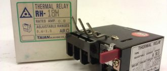
| Thermal relay | F, KK |
| Timing relay | KT |
| Voltage relay | KV |
| Impulse relay | KI |
| Photo relay | KL |
| Surge arrester, arrester | F.V. |
| fuse | F.U. |
| Voltage transformer | TV |
| Current transformer | T.A. |
| A frequency converter | UZ |
| Ammeter | PA |
| Wattmeter | PW |
| Frequency meter | PF |
| Voltmeter | PV |
| Active energy meter | P.I. |
| Reactive energy meter | PK |
| Heating element | E.K. |
| Photocell | B.L. |
| Lighting lamp | EL |
| Light bulb or light indicating device | H.L. |
| Plug or socket connector | XS |
| Switch or circuit breaker in control circuits | S.A. |
| Push-button switch in control circuits | S.B. |
| Terminals | XT |
Inserting wire numbers on a diagram
- Wire numbering dialog box by clicking the corresponding Wire numbers on the Diagram in the Insert wires/wire numbers . In the window that opens, specify the required numbering parameters.
- Select the numbering option: within the project, within the drawing, or by indicating individual wires by clicking the appropriate button. Depending on the option chosen, the further procedure will differ.
With the option Within the drawing , wire numbers will be automatically assigned and marked on the current drawing.
If you select the option Within the project , you will need to make the necessary numbering settings in the following window:
After clicking OK, a standard dialog for selecting files for processing will open, in which you will need to select project files that require the assignment and arrangement of wire numbers.
Well, for the option with indicating individual wires, it will be necessary to indicate the wires that are subject to numbering.
Copying/duplicating wire numbers on the diagram
In some cases, it is necessary to duplicate the wire number in different sections of the circuit. This situation, for example, arises when one circuit of a project is located on different sheets, or when it is necessary to emphasize the relationship of a particular wire to a given circuit.
- To start the procedure, click the Copy wire numbers Schematic tab Edit wires/wire numbers panel .
- Left-click on the wire in the place where you would like to set the additional number.
An additional wire number can only be placed if a number has already been assigned to this wire/circuit.
The additional number is placed in a layer for copies of wire numbers.
Graphic symbols in electrical diagrams
The documentation, which specifies the rules and methods for graphically designating circuit elements, is represented by three GOSTs:
- 2.755-87 – graphic symbols of contact and switching connections.
- 2.721-74 – graphic symbols of parts and assemblies for general use.
- 2.709-89 – graphic symbols in electrical diagrams of sections of circuits, equipment, contact connections of wires, electrical elements.
In the standard with code 2.755-87, it is used for diagrams of single-line electrical panels, conventional graphic images (CGI) of thermal relays, contactors, switches, circuit breakers, and other switching equipment. There is no designation in the standards for automatic devices and RCDs.
On the pages of GOST 2.702-2011, it is allowed to depict these elements in any order, with explanations, decoding of the UGO and the circuit diagram of the difavtomat and RCD itself. GOST 2.721-74 contains UGOs used for secondary electrical circuits.
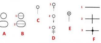
IMPORTANT: To designate switching equipment there is:
4 basic UGO images
| UGO | Name |
| Closing | |
| Breaking | |
| Switching | |
| Switching with neutral position |
9 functional signs of UGO
| UGO | Name |
| Arc suppression | |
| No self-return | |
| With self-return | |
| Limit or travel switch | |
| With automatic operation | |
| Switch-disconnector | |
| Disconnector | |
| Switch | |
| Contactor |
IMPORTANT: Designations 1 – 3 and 6 – 9 are applied to the fixed contacts, 4 and 5 are placed on the moving contacts.
Adding/removing callouts with wire numbers, quickly transferring wire numbers
AutoCAD Electrical allows you to easily add wire number callouts or, as already mentioned, configure the automatic addition of wire number callouts in the project/drawing properties. In addition, the user can delete some of the callouts and return the wire numbers assigned automatically.
- To start the procedure, click the Wire number callout Schematic tab Insert wires/wire numbers panel .
- Left-click on the wire number that you want to place on the leader. An auxiliary line will appear from the wire to the cursor, allowing you to track where the leader will go. Left-click on the point where you would like to end the leader line and press the right mouse button, Enter or Spacebar .
AutoCAD Electrical allows you to create leader lines from multiple segments. To do this, without pressing the right button, Enter or Space , drag the line further. This functionality has no practical use, but you never know who will need it. - To collapse an existing leader, after calling the command Wire number , you must enter “K” and specify the number of the wire whose leader you want to collapse.
- To move a wire number along a wire line, after calling the Wire Number Leader “B” in the command line and select the wire number that needs to be moved. After a cursor in the form of a square appears on the wire, move the wire number to a new location.
These and some other commands for working with wire numbers are also available in the Tracking menu , called up by right-clicking on a wire number.
Rate this article Rating 4.93 (15 Votes)