01/12/18
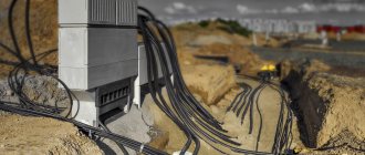
High-voltage cable lines (CL) are exposed to weight and soil shifts, temperature changes and other external factors. Testing cable lines with high voltage allows you to check the condition of the insulating layer and promptly replace damaged areas. Regularly conducting such checks is a necessary condition for the trouble-free operation of cable lines and helps prevent accidents, property damage and other unpleasant consequences.
Testing of 10 kV high voltage cable is required:
- after laying or replacing the cable - before filling the trench and turning on the power line;
- in relation to used cable lines - after a long outage and scheduled or unscheduled repairs;
- in relation to the cable sheath, which is laid in the ground and operates without electrical breakdowns - with a frequency of 5 years;
- for main cable lines - with an interval of 3 years;
- for reserves - with a 5-year frequency;
- for main and reserve cable lines supplying facilities of special importance - annually.
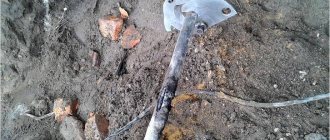
When carrying out excavation work, landslides, sedimentation or erosion of soil, extraordinary tests of cable lines are required. Additional checks are carried out upon completion of work.
Engineering has all the necessary licenses for testing high-voltage cables, a well-coordinated team of professionals and certificates that give the right to carry out all the necessary tests and measurements. By choosing the ProfEnergia electrical laboratory, you are choosing reliable and high-quality operation of your equipment!
If you want to order high-voltage tests, as well as for other questions, call: +7 (495) 181-50-34.
Test conditions
High voltage testing of power cables must be carried out by competent personnel who are at least 18 years of age and have undergone appropriate training. First, the CLs are inspected to identify defects in the insulating layer. Significant contamination is removed from the surface. The funnels are wiped clean.
The permissible air temperature for testing work is from 0 °C. First of all, the resistance of the cable insulation coating is measured with a megger. The required high voltage resistance is not lower than 1 MOhm. Such measurements make it possible to detect significant defects, violations of integrity and errors made during repair activities.
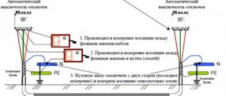
Insulation resistance is measured as follows:
1. Using an increased voltage device, check whether the cable is de-energized.
2. Grounding with clamps is installed on the cable cores.
3. On the opposite side, the cable outlets are left free. Warnings are placed here or a supervisory person is left to avoid accidental passers-by becoming energized.
4. Insulation resistance is measured with a megger, 60 seconds per wire.
5. The obtained measurement results are recorded in a notepad.
| Item no. | names | brand | basic error threshold |
| 1 | Megaohmmeter | ESO 202/2-G | ±15% |
| 2 | High voltage apparatus | AID-70 | ±4% |
| 3 | Voltage indicator with phasing tube | UVN-80-2M | — |
Methodology for testing 0.4 kV cable lines
The essence of the test is to measure the insulation resistance and test it using increased voltage. The first process is carried out using a megger for 1 minute, and each core can be tested individually or in groups of them. The readings obtained must comply with established standards, but it is important to take into account that the insulation resistance significantly depends on the condition of the end connections and the length of the cable, therefore such a check allows you to determine only grossly developed defects and errors made during repairs.
High voltage cable testing
Testing a 10 kV cable with increased voltage makes it possible to detect problems not detected by a megger and bring it to breakdown in faulty places. The increased voltage is supplied through a high-voltage wire of special equipment to 1 core, and portable grounding is applied to the rest. The voltage increases smoothly to a maximum of 60 kW.
The required test time (5-10 minutes) is then counted, and current and voltage leakage are carefully monitored. At the final minute, the current leakage is counted according to the readings of the microammeter. The voltage gradually decreases to zero. The high-voltage terminal of the equipment is grounded. All conductors are checked in the same way. The results of the checks are entered into a notebook. The permissible difference in current leakage between phases is not higher than 50%.
The cable is considered to have passed the test in the absence of:
- current surges, breakdowns;
- reducing the resistance of the insulating layer;
- increase in current leakage;
- surface discharges.
If the leakage current increases, the cable line is allowed to operate provided that it is monitored and tested more often. When a breakdown is detected, work is suspended and a search for faulty areas begins.
| SCL, kV | voltage, kV | DTU, mA | DKA |
| 6 | 36 | 0,2 | 8 |
| 10 | 45 | 0,3 | |
| 50 | 0,5 | ||
| 60 |
T. Permissible leakage currents and asymmetry coefficients for SCL.
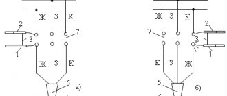
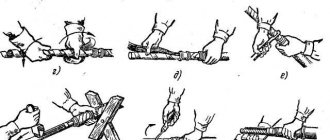
Checking the integrity of the cores
The integrity of the cores is checked with an ohmmeter. A closed circuit is formed with the core and conductor, and the resistance of the cable components is measured sequentially. Before using the ohmmeter, inspect it for damage. Then its trial testing is carried out with the probes separated and connected.
When checking with a mechanical device, to eliminate errors, it is placed on a horizontal plane. Due to the variability of the resistance of the insulating layer depending on external factors, the test takes at least 1 minute. The values are recorded from 15 seconds.
Checking the integrity of the cores includes the following steps:
- Removal of people from the tested part of the electrical installation.
- Grounding the terminals of the test object.
- Lack of voltage control.
- Removing and cleaning the cable insulation coating.
- Installation of measuring tentacles of a megohmmeter.
- Removing grounding.
- Check the insulation of all cores one by one.
- Recording the test results in the protocol.
- Disabling the machines and disconnecting the neutral wires from the terminal.
All inspection work is carried out wearing rubber gloves, with strict adherence to safety requirements. If a defect is detected, the part being tested is disassembled in order to find and eliminate the fault. Upon completion of the work, the residual charge of the megohmmeter is removed by a short circuit, discharging the probes with each other.
Types of tests
The first thing to establish is the resistance of the cable insulating sheath. In this case, measurements are carried out using a megger when a current voltage of 2,500 V is supplied. In this case, the resistance should be: for lines up to 1,000 V - at least 500 kOhm, and for lines over 1,000 V - at least 10 MOhm.
High voltage cable testing
It is recommended to measure cable insulation resistance both before and after testing the line with increased voltage.
The next test is to check by applying too much voltage. In this case, the accompanying leakage currents are measured, their nature and phase asymmetry are determined. The use of this method allows you to check the integrity and homogeneity of the cable much more accurately than with a megger (and for some types of defects such a check is the only possible one).
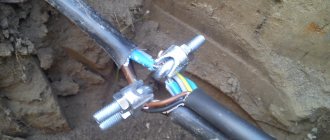
Before starting, ground the cable sheath, as well as all its cores, except the one being tested. Depending on the operating voltage of the line and the material of its insulation, the magnitude of the increased voltage, as well as the time it is applied to determine the breakdown, is different (you can use the table to correctly select the applied voltage and time).
It should also be remembered that if the cable being tested is located in parallel with another, then its phasing should be performed. To do this, operating voltage is applied to one end of the cable, and it is measured at the other.
The next type of check is monitoring oil-filled lines. During this process, a series of liquid measurements are carried out: for compliance with operating characteristics and for the absence of insoluble gases (the amount of the latter should not be more than 0.1%), and for lines above 110 kV - also soluble ones.
Checking the cable insulation
Checking the high-voltage line for integrity can also be done using an ohmmeter. To do this, one of the cores is determined (obviously intact) and further measurements are taken relative to it (at the same time, the resistance of the circuits of the remaining closed wires is determined).
Also, the current distribution in the conductors is measured. In this case, the amount of unevenness with a working cable should exceed 10%.
Cable testing method
On cable lines with an operating voltage of 20 kV or more, the electrical capacitance value is determined. This is done either by using a bridge circuit or using a voltammeter.
Ammeter-voltmeter method
High-voltage cables in plastic insulation are tested by applying an increased rectified voltage for 1 minute.
Cable sheaths in metal armor are checked for the presence of corrosion.
Also, periodic inspection of couplings, seals, cable manhole structures and other technical elements is carried out.
Testing of XLPE insulated cable
Cable with XLPE insulation is tested with alternating current voltage. By changing the polarity of the charge, it is possible to compensate and discharge the accumulated charges. When testing with a particularly low frequency voltage, it is possible to obtain the maximum rate of breakdown development and detect problems. To prevent damage to the cable line, the supplied voltage must have the form of a strictly symmetrical sinusoid.
Tests of cable lines, high-voltage tests of cross-linked polyethylene cables and inserts with XLPE insulation are mandatory before putting lines into operation and after completion of repair activities. Testing of a cable made of cross-linked polyethylene 10 kV and other voltages is carried out according to the instructions UP-B-1. Its requirements are presented in the table
Testing of power cables with impregnated paper insulation
When performing high-voltage tests on a cable with a metal sheath and screen , the screen and sheath are connected and - if the test takes a long time - an initial voltage is applied equal to about 40% of the full test voltage. Then testing the cables with 10 kV voltage is continued, gradually increasing it to the level of the established test voltage. The increase should not be faster than 1 kV per second. When adjusting stepwise, the voltage at each step should not exceed 5% of the main value of the full test voltage.
When a high-voltage test of a power cable is performed to measure the magnitude of the insulation breakdown voltage, the voltage is gradually increased until breakdown, and the rate of increase is no more than 2 kV per second.
It is imperative to conduct high-voltage tests of cables before commissioning to guarantee reliable and trouble-free operation of wired power cable lines, as well as systematically organize scheduled preventive tests of cable products. High voltage cable testing must include visual inspection and a series of test checks.
Specialists have all the necessary equipment, experience and permits for testing power cables over 1000V. Contact us by phone: (495) 669-40-84
The decision on the method of testing power cables, and what equipment will be used, is made by the specialists performing the tests. The measurement results are recorded in the power cable test report .
Testing the sheath of XLPE cable
The sheath of XLPE-insulated cables is often damaged due to mechanical or corrosive influences. If this defect is not corrected in a timely manner, the main insulation will lose its protective qualities and a breakdown will occur. The sheath of an XLPE cable with a voltage of 10–20 kV is tested with a voltage of 5 V DC for 10 minutes. When a breakdown is detected, a local search for the location of the defect is carried out.
Sheaths of 10–20 kV cables with XLPE insulation must be tested:
- before putting the cable line into operation;
- 2.5 years after the cable line was put into operation and thereafter with an interval of 5 years;
- after repair of the insulating layer;
- during excavations carried out in the security area of the cable line - due to the risk of damage to the protective shells.
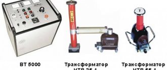
For comprehensive testing of cables, testing of 10 kV power cables and their sheaths, a special hardware complex is used. It identifies damaged areas and pinpoints the location of defects with high precision automatically using a step-by-step voltage method.
| type of power cable, kV | less than 1* | 6 | 10 | ||
| paper insulating sheath | |||||
| P | 6 | 36 | 60 | ||
| TO | 2,5 | ||||
| M | — | ||||
| plastic insulating shell | |||||
| P | 3,5 | 36 | 60 | ||
| TO | — | ||||
| M | — | ||||
| rubber insulating shell | |||||
| P | 6 | 12 | 20 | ||
| TO | |||||
| M | 6* | 12* | 20* | ||
7.1. Before testing the power cable with increased voltage, it is necessary to accurately establish the beginning and end of the test cable and ensure the safety of the work. 7.2 Check the cable insulation with a megohmmeter according to the MVI-2 insulation testing method 7.3. By installing the test voltage source (hereinafter referred to as the source) near the test object. 7.4. Ground the source with a flexible copper wire with a cross-section of 4 mm2. 7.5.Connect the source cables to the corresponding connectors of the control panel. 7.6. Remove the device control panel from the power source at a distance of at least 3m. Ground the control panel and connect it to the power supply. 7.10. Persons present during testing must be removed from the power source and the object being tested at a distance of at least 3 m. 7.7. Insert the special key from the device into the control panel switch and turn on the required type of test voltage; when testing the cable, this is a constant voltage, and the green signal should light up.
7.11. When working on rectified voltage “-”, in order to avoid failure of the source, as well as to correctly measure the value of the test voltage, it is necessary to monitor the position of the “KV” toggle switch 7.12. Rotate the test voltage regulator knob counterclockwise and set it to its original position until it stops. 7.13. Turn on the test voltage with the “STOP” button, and the red signal should light up. 7.14. By rotating the test voltage regulator knob in a clockwise direction and observing the kilovoltmeter readings, set the required test voltage value. When testing capacitive objects, including cables, it must be remembered that after the voltage regulator knob stops rotating, the test voltage on the object continues to increase (the kilovoltmeter needle continues to deviate) as the capacity is charged. 7.14. When working on a rectified test voltage “—”, measurement of a load current of up to 1 mA should be made with a microammeter, and the button that shunts this device should be pressed. 7.15. After completing the test, it is necessary to set the test voltage regulator knob, rotating it counterclockwise, to its original position until it stops. 7.16. Use the “STOP” button to turn off the test voltage and only then disconnect the device from the network and set it to the “O” position. Control over the removal of residual capacitive charge from the test object must be carried out by observing the kilovoltmeter of the device - the kilovoltmeter needle should be on the numerical o. 7.17. The voltage rise to 25-30% of the test voltage can be done at any speed, however, the rise speed is limited by surges in the charging current in the cable. Next, the voltage is increased to the test voltage smoothly at a rate of 1-2% of the test voltage per second, the total duration of the voltage rise, expressed in seconds, must be at least a value numerically equal to the value of the test voltage, expressed in kilowatts. 7.18. During the test, it is necessary to periodically check the leakage current; the value of this current is not standardized, but its fluctuation or increase is the first sign of a cable defect. 7.19. When the cable is in satisfactory condition, the leakage current when the voltage rises first increases sharply (due to charging the cable capacitance), then quickly drops to 10-20% of the maximum value. 7.20. When testing, attention is paid to the asymmetry of the leakage current across phases, i.e. The largest difference in leakage current values for a cable with satisfactory insulation, the asymmetry coefficient does not exceed 2 for a 6 kV cable. and 3 for 10kV cable. 7.21.After waiting the required time, the voltage gradually decreases to 30% of the test value, then the voltage drop can be accelerated. 7.22. After removing the voltage on the cable under test, the charge voltage remains for a long time; all neighboring cables, although not connected to the power source, are also charged to a voltage dangerous to human life, therefore, before testing the cable, all its cores, except the one under test, must be grounded. Adjacent cables are also grounded if they are not live. 7.23.After removing the test voltage, disconnecting the test installation from the network, the cable must be discharged; for this, a special discharge rod or a resistance of approximately 20,000 ohms is used. 7.24. It is necessary to discharge the tested cable core first through resistance, and then without it, then apply grounding. 7.25. At the end of the test of all cable cores, the insulation resistance of each core relative to the ground and between each other is measured again with a 2500V megohmmeter, after which the cable must be discharged again. 7.26. The results of the cable test are considered satisfactory if there were no sliding discharges, leakage current impulses or its increase after reaching a steady value and if the insulation resistance measured with a megohmmeter after the test remained the same. 7.27. The test voltage is taken in accordance with Table No. 7.1, taking into account local operating conditions of power cable lines. 7.28. For cables with voltages up to 10 kV with paper and plastic insulation, the duration of application of the full test voltage during acceptance tests is 10 minutes, and during operation 5 minutes. 7.29. For cables with rubber insulation for voltage 3-10 kV, the duration of application of the test voltage is 5 minutes. 7.30. Permissible leakage currents depending on the test voltage and permissible values of the asymmetry coefficient when measuring leakage current are given in table No. 7.2.
Table No. 7.1
| Test category | Paper-insulated cables for voltage, kV | ||||||||
| 1 | 2 | 3 | 6 | 10 | |||||
| P | 6 | 12 | 18 | 36 | 60 | ||||
| TO | 2,5 | 10-17 | 15-25 | 36 | 60 | ||||
| m | — | 10-17 | 15-25 | 36 | 60 | ||||
| Test category | Cables with plastic insulation for voltage, kV | Cables with rubber insulation for voltage, kV | |||||||
| 3 | 6 | 10 | 3 | 6 | 10 | ||||
| P | 15 | 36 | 60 | 6 | 12 | 20 | |||
| TO | 7,5 | 36 | 60 | 6 | 12 | 20 | |||
| m | 7,5 | 36 | 60 | 6** | 12** | 20** | |||
P - when commissioning new electrical equipment that has undergone restoration or major repairs and reconstruction at a specialized repair enterprise. K - during major repairs at an energy enterprise. M - between repairs. **- after repairs not related to cable reinstallation, the insulation is checked with a mega-ohmmeter for a voltage of 2500V, and testing with increased rectified voltage is not performed.
Table No. 7.2.
| Cables voltage kV. | Test voltage kV | Permissible values of leakage currents, mA. | Acceptable coefficient values asymmetry (Imax/Imin) |
| 6 | 36 | 0,2 | 2 |
| 10 | 50 | 0,5 | 3 |
7.31. Frequency of tests during operation of cable lines for voltage 2-3 5 kV: A) once a year for cable lines during the first five years after commissioning, and then: -1 time every two years for cable lines, which during the first five years there were no emergency breakdowns and breakdowns during preventive tests and once a year for cable lines on the routes of which construction and repair work was carried out and on which emergency insulation breakdowns systematically occur. -1 time every three years for cable lines in closed areas (substations, factories, etc.) -during major repairs of equipment for cable lines connected to units, 6-10 kV cable jumpers between busbars and transformers in transformer substations and distribution substations. B) it is allowed not to carry out tests: - for cable lines up to 60 m long, which are outputs from switchgear and transformer substations to overhead lines and consist of two parallel cables. - for cable lines with a service life of more than 15 years, on which the specific number of failures due to electrical breakdown is 30 or more failures per 100 km. in year. - for cable lines subject to reconstruction or decommissioning in the next 5 years. 7.32. It is prohibited to carry out high-voltage tests of cable lines during a thunderstorm, or if there is condensation on the walls inside the high-voltage compartment of the mobile high-voltage testing laboratory. 7.33. The insulation is considered to have passed the high voltage test if there were no breakdowns, voltage drops or increased leakage current.
Front panel of the control panel of the AID-70M device
1. Power off button 2. AC voltage selection button 3. DC voltage selection button 4. Test voltage regulator 5. “STOP” button 6. Test voltage switch button 7. Milliammeter shunt button
Prices for electrical measuring work "PROFENERGIYA":
| Services | Unit | Cost per unit of measurement, rub. | |
| Electrical installations over 1000 V to 35 kV | |||
| Checking compliance of the installed electrical installation with the requirements of the design documentation | inspection | From 3000 | |
| Checking the presence of a circuit between grounding conductors and grounded elements | dot | From 25 | |
| Testing of fuses, fuse-disconnectors for voltages over 1 kV. | PC. | From 490 | |
| Testing of power cable lines with voltage up to 20 kV. | PC. | From 9500 | |
| Testing of power cable lines with cross-linked polyethylene insulation with voltage up to 35 kV. | Trial | From 8000 | |
| Testing of power transformers, autotransformers, oil reactors and grounding arc arresters with rated voltage up to 35 kV. power up to 63000 kVA | PC. | From 15000 | |
| Testing of switchgear and switchgear. | PC. | From 14900 | |
| Testing of oil, air, vacuum circuit breakers, disconnectors, short circuiters and separators. | PC. | From 1400 | |
| Testing of complete busbars (busbars). | PC. | From 2500 | |
| Testing of busbars and connecting busbars. | PC. | From 2500 | |
| Testing of valve, tubular arresters and surge suppressors. | PC. | From 4000 | |
| Testing of bushings and bushings. | PC. | From 5000 | |
| Testing of suspension and support insulators | PC. | From 6000 | |
| Testing of dry current-limiting reactors. trial | Trial | From 5000 | |
| Inspection of cells (checking and adjusting relay equipment) | Complex | From 15000 | |
| Testing of AC electric motors with rated voltage up to 20 kV. | Complex | From 20000 | |
| Checking switchgear and their connections | Complex | From 10000 | |
| Testing of electrical equipment with increased voltage 1 kV industrial frequency | Measurement | From 500 | |
| Testing of synchronous generators and compensators | Measurement | From 8000 | |
| Testing of measuring current transformers | Trial | From 5000 | |
| Testing of voltage transformers | Trial | From 3500 | |
| Testing of dry current-limiting reactors. | Trial | From 4500 | |
| Capacitor testing. | PC. | From 1800 | |
| Transformer oil testing | Sample (1 liter) | From 8000 | |
| Testing power lines with voltages above 1 kV | Complex | From 20000 | |
| Comprehensive testing | |||
| Carrying out electrical measuring work with the preparation of a technical report from 1000V to 35kV | |||
| Acceptance tests. | Complex of works | From 20000 | |
| Performance tests. | Complex of works | From 20000 | |
| For certification purposes | Complex of works | From 8000 | |
| Engineer visit | Departure | For free | |
| Drawing up single-line diagrams | PC. | From 2000 | |
| Drawing up a grounding device passport | PC. | From 10000 | |
Locations of insulation defects are also determined in stage 2. First, preliminary localization is carried out using the loop method and precision bridge, and then precise identification of defective locations is carried out using the step voltage technique.
To identify locations of damage to the cores themselves, various technologies are used:
- for a 3-core cable – burning;
- for initial localization - non-burning methods;
- for high-precision detection of defects - acoustic method.
Timely testing of high-voltage lines is necessary to increase the reliability of electrical networks and increase the period of their uninterrupted use.
| Carrying out electrical measuring work with the preparation of a technical report from 1000V to 35kV | |||
| Acceptance tests. | Complex of works | From 20000 | |
| Performance tests. | Complex of works | From 20000 | |
| For certification purposes | Complex of works | From 8000 | |
| Engineer visit | Departure | For free | |
| Drawing up single-line diagrams | PC. | From 2000 | |
| Drawing up a grounding device passport | PC. | From 10000 | |
Modern electrical capabilities make it possible to provide energy to any national economic facility. Due to the density of urban infrastructure, as well as the minimum distance between industrial and manufacturing enterprises, power lines are equipped with high voltage power cables. When distributed to consumption points, it is transformed to the required level.
Why are tests carried out?
During long-term operation, cable lines are inevitably exposed to external influences.
The factors that determine the wear of the CL include:
- sharp amplitude of seasonal temperatures;
- groundwater activity;
- excessive atmospheric activity (ice storm is especially dangerous);
- soil mobility.
In addition, constant overloading of lines has a detrimental effect. As the insulating layer wears out, the CL gradually loses its original performance characteristics.
To prevent external factors from having a destructive effect, it is recommended to systematically test cable lines with high voltage. Proper organization of testing ensures the flawless functioning of networks, as well as minimizing emergency and abnormal situations.
Test results
Testing of a 0.4 kV cable line is carried out in accordance with current rules and regulations. Testing is carried out:
- after installation or re-cabling before activating the equipment;
- after repairs have been completed.
Note that testing a 0.4 kV cable line takes from 1 to 15 minutes. The duration depends on the type of insulation used on the wires, as well as the type of testing. So, before connecting equipment after installation or relaying for cables with paper or plastic insulation, manipulation is performed for 1-10 minutes. After repair, the time increases to 15 minutes. For rubber-insulated wires, the test is carried out for 5 minutes, regardless of its type.
The permissible leakage current value for the corresponding cables is up to 0.2 mA. If the indicator is different, the equipment cannot be used.
Immediately after testing, a Protocol is drawn up. Based on this, an application for cable connection is submitted. The validity period of the Protocol is 3 days. If you do not apply for connection within 72 hours, testing will have to be repeated.
Frequency of testing cable lines
Tests are carried out immediately after laying cables, after their relocation and repair work. Their frequency is determined by established standards and requirements, which must be carefully adhered to in order to avoid emergencies and various breakdowns. For balance holders, that is, network organizations, periodic inspections are not regulated, so it is necessary to be guided by the standards for electrical installations up to 1000 V for buildings and structures. The frequency is once every 1-2 years. If you would like to receive more detailed information regarding events, our managers will advise you in detail at the most convenient time.
Who has the right to perform an inspection?
Since this type of work is a task of increased complexity and contains a potential danger to health and even life, employees with permits are allowed to test cables.
For example, when working with a megohmmeter, electrical safety group III is required, and for performers of a full range of work - IV. The organizer (leader) is required to have group V in electrical safety. The fact of admission is recorded in the appropriate certificate. In addition to the group, it reflects information about aptitude tests.
In this case, the minimum work experience in the profile is 3 full months. This refers to direct experience in testing cables that took place during the specified 3 months. Without the practice of high-voltage testing, even an actual three-month presence in the profession is considered insignificant.
Tests: how they are carried out
The first check for serviceability is carried out immediately after laying the cable, even before the official commissioning. Later in everyday functionality this operation is repeated.
Work is not carried out at sub-zero temperatures. Even a slight drop in the mercury column beyond zero is a good reason to cancel tests. The fact is that icy water particles have dielectric properties (some of them are very likely to get into the cable). High voltage tests will be useless or the results obtained will not be reliable.
The test method with increased rectified voltage is that it is applied to each cable core (while the rest are grounded).
Leakage is defined as follows:
- insulation test to earth;
- phase-to-phase insulation testing.
The performance of the CL is recognized if shocks and small discharges are not traced. When completed, the line is discharged.
High-voltage testing of cross-linked polyethylene cable (regulations)
| Periodicity |
Important ! If there are no breakdowns, the cable sheath is inspected for integrity once every 5 years. | |
| First method | Second method | |
| Testing 10 kV XLPE cable | It is carried out using alternating voltage with a frequency of 0.1 Hz. Duration: 30 minutes. If the cable line repair work has just finished, 20 minutes is enough. Important ! An industrial diagnostic VLF installation for XLPE cables is used. Test procedure:
| Checking CL 10 6 kV is performed with alternating voltage (10 or 6 kV, respectively). Voltage is applied between the core and the screen. Duration - 24 hours. Test procedure:
Important ! Timing begins from the moment the voltage rises to the maximum level. |
| Current leaks considered normal | For a 6 kV cable - up to 200 µA. For 10 kV - no more than 500 µA. | |
A licensed engineer conducts 10 kV cable testing with quality assurance. Availability of licenses from Rostekhnadzor and SRO, modern equipment - a guarantee of the accuracy of the results obtained. Based on the test results, our specialists prepare a report.
Frequency of tests during operation
Cables for voltage 2-35 kV:
a) once a year - for cable lines during the first 2 years after commissioning, and thereafter:
- 1 time every 2 years - for cable lines in which during the first 2 years there were no emergency breakdowns or breakdowns during preventive tests, and 1 time per year for cable lines on the routes of which construction and repair work was carried out and on which systematically occur emergency insulation breakdowns;
— 1 time every 3 years — for cable lines in closed areas (substations, factories, etc.);
— during major repairs of equipment for cable lines connected to units, and 6-10 kV cable jumpers between busbars and transformers in transformer substations and distribution substations;
b) it is allowed not to carry out the test:
— for cable lines up to 100 m long, which are outputs from switchgear and transformer substations to overhead lines and consist of two parallel cables;
— for cable lines with a service life of more than 15 years, on which the specific number of failures due to electrical breakdown is 30 or more failures per 100 km per year;
— for cable lines subject to reconstruction or decommissioning in the next 5 years;
c) it is allowed, by order of the technical manager of the energy enterprise, to establish other values of test frequency and test voltages:
— for supply cable lines with a service life of more than 15 years with the number of connecting couplings more than 10 per 1 km of length;
- for cable lines with a voltage of 6-10 kV with a service life of more than 15 years, on which only KVV and KVB types of terminations and locally manufactured couplings are installed, with a test voltage value of at least 4 U
nom and frequency at least once every 5 years;
— for cable lines with a voltage of 20-35 kV during the first 15 years the test voltage should be 5 U
nom, and hereinafter 4
U
nom.
Cables for voltage 110-500 kV:
- 3 years after commissioning and thereafter once every 5 years.
Cables for voltage 3-10 kV with rubber insulation:
a) in stationary installations - once a year;
b) in seasonal settings - before the onset of the season;
c) after a major overhaul of the unit to which the cable is connected.
Table 29.1
Test rectified voltage, kV, for power cables
| Test category | Paper-insulated cables for voltage, kV | ||
| up to 1 | |||
| P | |||
| TO | 2,5 | 10-17 | 15-25 |
| M | — | 10-17 | 15-25 |
| Test category | Cables with plastic insulation for voltage, kV | Cables with rubber insulation for voltage, kV | ||||
| 0.66* | 1* | |||||
| P | 3,5 | 5,0 | ||||
| TO | — | 2,5 | 7,5 | |||
| M | — | — | 7,5 | 6** | 12** | 20** |
* Rectified voltage testing of single-core cables with plastic insulation without armor (screens) laid in air is not carried out.
** After repairs not related to cable reinstallation, the insulation is checked with a megohmmeter for a voltage of 2500 V, and testing with increased rectified voltage is not performed.
Table 29.2
Leakage currents and asymmetry factors for power cables
| Cables voltage, kV | Test voltage, kV | Permissible values of leakage currents, mA | Allowable values of the asymmetry coefficient, ( I max /I min) |
| 0,2 | |||
| 0,3 | |||
| 0,5 | |||
| 0,5 | |||
| 1,5 | |||
| 1,8 | |||
| 2,0 | |||
| 2,5 | |||
| Not standardized | Not standardized | ||
| Same | Same | ||
| » | » | ||
| » | » | ||
| » | » |
P, K. Determination of the integrity of cable cores and phasing of cable lines
Performed in operation after completion of installation, reinstallation of couplings or disconnection of cable cores.
P. Determination of cable core resistance
Produced for lines with voltages of 20 kV and above.
The direct current resistance of cable cores, reduced to a specific value (per 1 mm2 section, 1 m length, at a temperature of 20 ° C), should be no more than 0.01793 Ohm for copper and 0.0294 Ohm for aluminum cores. The measured resistance (reduced to specific value) may differ from the specified values by no more than 5%.
P. Determination of the electrical working capacitance of cables
The determination is made for lines with a voltage of 20 kV and above. The measured capacity, normalized to a specific value (per 1 m length), should differ from the values during factory tests by no more than 5%.
M. Control of the degree of drying of vertical sections
The degree of drainage of vertical sections is controlled by the decision of the technical manager of the energy enterprise.
Control is carried out for cables with paper insulation impregnated with a viscous composition for a voltage of 20-35 kV by measuring and comparing the heating of metal sheaths at different points in the vertical section of the line. The difference in heating of individual points at currents close to the rated ones should not be more than 2-3 °C.
P, K. Measurement of current distribution along single-core cables
The uneven distribution of currents along the conductive cores and sheaths (screens) of cables should not be more than 10%.
P, M. Checking anti-corrosion protection
When accepting lines into operation and during operation, the operation of anti-corrosion protection is checked for:
— cables with a metal sheath laid in soils with medium and low corrosive activity (soil resistivity above 20 Ohm/m), with an average daily leakage current density into the ground above 0.15 mA/dm2;
— cables with a metal sheath laid in soils with high corrosive activity (soil resistivity less than 20 Ohm/m), at any average daily current density into the ground;
— cables with an unprotected sheath and destroyed armor and protective coverings;
— steel pipeline of high-pressure cables, regardless of the aggressiveness of the soil and types of insulating coatings.
During the test, potentials and currents in the cable sheaths and electrical protection parameters (current and voltage of the cathode station, drainage current) are measured in accordance with the Guidelines for the electrochemical protection of underground energy structures from corrosion.
The assessment of the corrosive activity of soils and natural waters should be carried out in accordance with the requirements of GOST 9.602-89.
The timing of measurements of stray currents in the ground (M) is determined by the technical manager of the energy enterprise, but at least once every 3 years.
P, K, M. Determination of characteristics of oil and insulating liquid
The determination is made for all elements of oil-filled cable lines for a voltage of 110-500 kV and for end joints (inputs into transformers and switchgear) of plastic-insulated cables for a voltage of 110 kV.
Samples of oils of grades S-220, 5-RA, MN-3 and MN-4 and insulating liquid of grade PMS must meet the requirements of the standards of Table. 29.3 and 29.4.
Testing of oil and insulating liquid samples is carried out upon commissioning, after 1 year, then after 3 years and subsequently once every 6 years. If the values of electrical strength and degree of degassing of MN-4 oil comply with the standards, and the values of tg δ, measured according to the GOST 6581-75 method, exceed those indicated in the table. 29.4, the oil sample is additionally kept at a temperature of 100 °C for 2 hours, periodically measuring tg δ. When the tg δ value decreases, the oil sample is kept at a temperature of 100 °C until a steady value is obtained, which is taken as the control value.
It is allowed for low-pressure MNCLs to take oil samples from the collector, and in case of unsatisfactory results, from pressure tanks.
Table 29.3
Standards for quality indicators of oils of grades S-220 , MN-3 and MN-4 and insulating liquid of grade PMS
| Oil quality indicator | For a newly introduced line | In use | ||||
| S-220, 5RA | MN-3, MN-4 | PMS | S-220, 5RA | MN-3, MN-4 | PMS | |
| Breakdown voltage in a standard vessel, kV, not less | 42,5 | 42,5 | ||||
| Degree of degassing (dissolved gas), %, no more | 0,5 | 1,0 | — | 0,5 | 1,0 | — |
Note. Tests of oils not listed in the table. 29.3, produce in accordance with the manufacturer's requirements.
Table 29.4
Dielectric loss tangent of oil and insulating liquid (at 100 °C), %, no more, for voltage cables, kV
| Service life of cable lines | 150-220 | 330-500 | |
| Upon commissioning | 0,5/0,8* | 0,5/0,8* | 0,5/- |
| In operation for: | |||
| first 10 years | 3,0 | 2,0 | 2,0 |
| more than 10 to 20 years | 5,0 | 3,0 | — |
| over 20 years | 5,0 | 5,0 | — |
* The numerator indicates the value for oils of the S-220 and 5-RA brands, the denominator for MN-3, MN-4 and PMS.
P, K, M. Determination of the volume of undissolved gas (impregnation test)
The test is carried out for oil-filled cable lines for voltages of 110-500 kV.
The content of undissolved gas in the insulation should be no more than 0.1%. Frequency - in accordance with clause 29.9.