The principle of operation of the garland
The electrical circuit of the device is shown in the photo. The voltage from the network is rectified through resistors and diodes, and then supplied to the microcontroller. The capacitor smoothes out network noise. The button in the device in its initial position is in an open state. If it is closed, the controller operating modes change. The latter controls the operation of the thyristors.
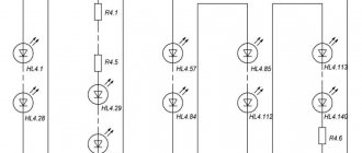
After the power passes through the thyristors, it goes to the LED elements of the garland. The number of device outputs directly determines how colorful the display will be. If the garland has two outputs, then this circuit is the simplest. In this case, an alternating color change occurs: some LEDs go out, others light up. The above circuit consists of four channels, which are connected in series with thyristors.
It is worth noting that one of the power conductors is always connected to the outermost LED of each line.
How to make a garland of light bulbs with “running lights”
To create a festive illumination with “running lights” you will need at least 3 garlands, and each of them should consist of several groups of parallel connected “flashlights”. To recreate such a glowing effect, you will need a three-phase multivibrator with transistors, which are designated VT1, TV2 and VT3. A 0.1 µF capacitor is installed in the arm of the second transistor, which greatly simplifies the launch of the product.
You will need a two-half-wave rectifier to power the machine. We are talking about rectifier diodes VD1, VD2, VD3 and VD4. Do not confuse them with LEDs!
This option will allow you to create a wide variety of shapes - from a circle, triangle or square to a heart and thematic figures (snowman, Santa Claus, Snow Maiden, deer in harness).
Remaking a Chinese garland
Most consumers do not have a very good opinion about Chinese products. The garlands also do not stand out against the general background of goods from China: poor-quality connections, too thin conductors, cheap construction materials. As a result, such garlands (including their control units) often fail.
A breakdown of any of the circuit elements can affect the functioning of the garland. For example, a non-working capacitor causes light bulbs to flicker. A thyristor failure entails the shutdown of one of the channels. A burnt-out diode or a failed diode bridge lead to complete system inoperability.
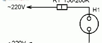
Damaged parts must be replaced with new ones. If you do not have sufficient knowledge in the field of electrical engineering or do not want to bother with repairs, an extremely simple but effective scheme is recommended. We connect the garland directly with a plug, and build a starter from a fluorescent lamp into one of the cable conductors. However, this scheme is only effective for ordinary light bulbs. As for the LED garland, its functionality will be restored in this case, but the light will become dimmer.
LED garlands
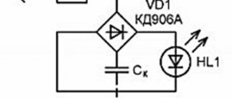
Such products have recently become widespread. In this regard, low-power elements appeared on the garlands instead of light bulbs. The circuit of the Chinese LED garland differs little from the standard one. But, given the fact that the LED is designed for a much lower voltage, each of them will have a resistor in the circuit for a 220 V network. In another embodiment, a step-down transformer will be implemented at the system input.
In addition to the usual circuit, where the elements are arranged in series, there is a circuit of a Chinese garland with LEDs placed in parallel. With this option, even the burnout of several light elements at once will not introduce dissonance into the overall picture.
Repair of a Chinese product
Chinese garlands with permanent lamps can also be repaired. Pre-prepared:
- several identical garlands, they will serve as a donor of parts for a damaged product;
- tester;
- insulating tape;
- new lamps;
- wire cutters and a utility knife for working with wires.
The garland is disconnected from the network and the controller is disassembled, the soldering of the wires in the board is checked. Two pads for connecting the power cord are attached to one side, and five for color channels to the second. Moreover, one is located separately from the four; the common wire of all channels is connected to it. After checking the solders, the controller is closed.
Sometimes Chinese products contain lamps that short out when they burn out. This diode has less resistance than other lamps. The faulty part is replaced after de-energizing the garland. All connections must be soldered and insulated with tape. Due to the lack of shorted parts, the entire section of the same color goes out. In this case, check sections of the garland by cutting it in half. The lamp is then replaced, all cuts are connected and insulated.
Don't throw away a damaged Christmas tree garland. All damage can be repaired independently. Also, a broken or burnt-out lamp cannot be short-circuited, since the remaining diodes will begin to receive a higher voltage. This will lead to their burnout. After repairing the product, the entire cord and connections are inspected, and open areas are isolated.
New Year's garlands
The approaching New Year holiday is always associated with both increased troubles. This cup does not bypass radio amateurs, who begin to puzzle over decorating the Christmas tree with various kinds of light decorations and bright effects. A selection of schematic electrical diagrams of control devices for garlands and other light sources for the New Year holiday is offered.
The circuit of this switch has the illusion of smoothly switching on and off a Christmas tree garland.
Multi-channel garland switch
This machine is capable of controlling eight low-power garlands and provides such effects as running fire, running shadow, flickering and simple chaotic switching.
If any radio amateur decides to repeat these designs, he should pay attention to some errors and inaccuracies in the publication.
Twinkling stars
Perhaps the simplest implementation of the lighting effects of a garland is the use of starters from fluorescent lamps. Just a few details, a minimum of labor, a little diligence, and a joyful mood is guaranteed.
Christmas tree garland switch
The automatic switch circuit for three New Year's garlands on just four microcircuits provides more than a dozen lighting effects: running lights, running shadows, turning on the garlands one at a time, a smooth increase in the glow, blinking all the garlands at once, etc.
Six LED flasher designs
Based on the widely used AL307B red LEDs, simple amateur radio designs can be made. Below are diagrams of flashing lights on transistors and on microcircuits, as well as a diagram of a running light and a running arrow.
?Scheme of the simplest electronic device “running lights” for beginner radio amateurs.
Automatic LED switch
A very simple and interesting device on digital chips for automatically switching LEDs, which can be assembled by any novice radio amateur. In the classic version, this is a machine with the “running fire” effect. But it can easily be turned into a kind of “random number” generator, of which there will be few, however, but four digits.
A simple LED flasher circuit powered by a single galvanic cell.
New Year's garlands (two)
Here we have a diagram of a programmable four-channel automatic lighting effects “running fire”, “running shadow” and two options for switching on garlands in pairs with the ability to change the direction and frequency of channel switching. And also a simple simple arrangement of running lights on garlands of small-sized incandescent lamps with automatic switching of the direction of movement.
Mini-automatic LED lighting effects
A distinctive feature of the given circuit of the machine is the chaotic change of operating modes of the switch, as a result of which there is no eye fatigue and the perception of light effects is improved.
A simple 4-color multi-channel garland based on the ATTINY13A microcontroller
As the people say, prepare your sleigh in the summer... You probably decorate the Christmas tree with all sorts of garlands for the New Year, and most likely they have long since become boring with the monotony of their blinking. I would like to do something so that, wow, it blinks just like on the capital’s Christmas trees, only on a smaller scale. Or, as a last resort, hang it on the window so that this beauty illuminates the city from the 5th floor. But alas, there are no such garlands for sale. Actually, this is exactly the problem that had to be solved two years ago. Moreover, due to laziness, 2 years passed from idea to implementation, as usual, and everything was done in the last month. Actually, you will have more time (or I don’t understand anything about human psychology, and everything will be done exactly the same in the last 2 weeks before the new year?).
The result is a fairly simple design of individual modules with LEDs, and one common one that transmits commands from the computer to the network of these modules.
The first version of the module was conceived to connect them to the network via two wires, so that there would be less confusion and all that - but it didn’t work out; in the end, a fairly powerful and high-speed switch was required to switch the power of even a small number of modules - an obvious overkill for the simplicity of the design, so I gave preference the third wire is not so convenient, but it is much easier to organize a data transmission channel.
How everything works.
The developed network is capable of addressing up to 254 slave modules, which will be further called SLAVE - they are connected by only 3 wires, as you guessed - two wires are +12V power supply, common and the third is signal. they have a simple scheme:
As you can see, it supports 4 channels - Red, Green, Blue and Violet. True, according to the results of practical testing, purple is clearly visible only close up, but how! Also, due to the fact that the colors are located too far from each other, the color mixing can only be seen from 10 meters away, if you use RGB LEDs the situation will be somewhat better. In order to simplify the design, we also had to abandon quartz stabilization - firstly, the extra output is taken away and secondly, the cost of a quartz resonator is quite noticeable and thirdly, there is no urgent need for it. A protective cascade is assembled on the transistor so that the controller port is not knocked out by static - the line can still be quite long, in extreme cases only the transistor will suffer. The cascade is calculated in MicroCap and has an approximate response threshold of about 7 volts and a weak dependence of the threshold on temperature.
Naturally, in the best traditions, all modules respond to address number 255 - this way you can turn them all off at the same time with one command.
A module called MASTER is also connected to the network - it acts as an intermediary between the PC and the network of slave SLAVE modules. Among other things, it is a source of reference time for synchronizing slave modules in the absence of quartz stabilization in them.
Scheme:
The circuit contains optional potentiometers - they can be used in a program on a PC for convenient and quick adjustment of the desired parameters; at the moment this is implemented only in the test program in the form of the ability to assign any of the potentiometers to any of the 4 channels. The circuit is connected to a PC via a USB-UART interface converter on an FT232 chip.
An example of a packet sent to the network:
Its beginning:
Electrical characteristics of the signal: log.0 corresponds to +9...12V, and log.1 corresponds to 0...5V.
As you can see, data is transmitted sequentially, at a fixed speed of 4 bits. This is due to the necessary margin for error in the data reception speed - SLAVE modules do not have quartz stabilization, and this approach guarantees data reception with a deviation in the transmission speed of up to +-5% in excess of those that are compensated by the software method based on measuring the calibrated interval at the beginning of data transmission which provides resistance to reference frequency drift by another +-10%.
Actually, the algorithm of operation of the MASTER module is not so interesting (it is quite simple - we receive data via UART and forward it to the network of slave devices), all the most interesting solutions are implemented in SLAVE modules, which actually allow you to adapt to the transmission speed.
The main and most important algorithm is the implementation of a 4-channel 8-bit software PWM which allows you to control 4 LEDs with 256 gradations of brightness for each of them. The implementation of this algorithm in hardware also determines the data transfer rate on the network - for software convenience, one bit is transmitted for each step of PWM operation. A preliminary implementation of the algorithm showed that it runs in 44 clock cycles, so it was decided to use a timer configured to interrupt every 100 clock cycles - this way the interrupt has time to be guaranteed to be executed before the next one and execute part of the code of the main program. At the selected clock frequency of the internal oscillator of 4.8 MHz, interrupts occur at a frequency of 48 kHz - this is the bit speed the network of slave devices has and the PWM is filled at the same speed - as a result, the frequency of the PWM signal is 187.5 Hz, which is quite enough not to notice the flickering of the LEDs. Also, in the interrupt handler, after executing the algorithm responsible for generating PWM, the state of the data bus is recorded - it turns out approximately in the middle of the timer overflow interval, this simplifies data reception. At the beginning of receiving the next 4-bit packet, the timer is reset, this is necessary for more accurate reception synchronization and resistance to reception speed deviations. The result is the following picture:
The implementation of the algorithm for adjusting the transmission speed is interesting. At the beginning of the transmission, MASTER issues a pulse with a duration of 4 bits of log.0, from which all slave modules determine the required reception speed using a simple algorithm:
LDI tmp2, st_syn_delay DEC tmp2 ;<+ BREQ bad_sync ; | SBIC PINB, cmd_port; | RJMP PC-0x0003 ;-+
st_syn_delay = 60 - a constant that determines the maximum duration of the starting pulse, which is taken to be approximately 2 times the nominal value (for reliability)
Using an experimental method, the following dependence of the resulting number in tmp2 was established when the clock frequency deviates from the nominal:
4.3Mhz (-10%) 51 units (0x33) corresponds to 90 timer ticks to return the reception speed to nominal 4.8Mhz (+00%) 43 units (0x2B) - corresponds to 100 timer ticks (nominal) 5.3Mhz (+10%) 35 units (0x23) - corresponds to 110 timer ticks to return the reception speed to nominal
Based on these data, the correction factors for the timer interrupt period were calculated (this is how the reception speed is adjusted to the existing clock frequency of the controller):
Y(x) = 110-x*20/16 x = tmp2 - 35 = (0, 1, 2, 3, 4, 5, 6, 7, 8, 9, 10, 11, 12, 13, 14, 15 , 16) Y(x) = (110, 108.75, 107.5, 106.25, 105, 103.75, 102.5, 101.25, 100, 98.75, 97.5, 96.25, 95, 93.75, 92.5, 91.25, 90)
The numbers are rounded to whole numbers and stored in the EEPROM.
If, when applying voltage to the module, hold the line in the logical state “1”, a calibration subroutine will be activated, which will allow you to measure the period of the PWM signal with a frequency meter or oscilloscope without correction and, based on the measurements, judge the deviation of the clock frequency of the module controller from the nominal one, with a strong deviation of more than 15% The built-in RC oscillator calibration constant may need to be adjusted. Although the manufacturer promises calibration at the factory and deviation from the nominal value of no more than 10%.
At the moment, a Delphi program has been developed that allows you to reproduce a previously compiled pattern for 8 modules at a given speed. As well as a utility for working with a separate module (including reassigning the module address).
Firmware. for the SLAVE module, only fuses CKSEL1 = 0 and SUT0 = 0 need to be flashed. The rest should be left unflashed. The contents of the EEPROM are flashed from the file RGBU-slave.eep, if necessary, you can immediately set the desired address of the module on the network - the 0th byte of the EEPROM, by default it is flashed as $FE = 254, address 0x13 contains the calibration constant of the built-in RC oscillator of the controller, at a frequency of 4.8 MHz it does not load automatically, so you need to use the programmer to read the factory calibration value and write it in this cell - this value is individual for each controller, with large frequency deviations from the nominal value, you can change the calibration through this cell without affecting the factory value.
for the MASTER module it is necessary to flash only fuses SUT0 = 0, BOOTSZ0 = 0, BOOTSZ1 = 0, CKOPT = 0. Leave the rest unflashed.
Finally, a small demonstration of the garland located on the balcony:
In fact, the functionality of the garland is determined by the program on the PC - you can create color music, stylish iridescent room lighting (if you add LED drivers and use powerful LEDs) - etc. What do I plan to do in the future? The plans include a grid of 12 modules with 3-watt RGB LEDs, and room lighting based on pieces of 12-volt RGB tape (you only need field-effect transistors for switching the tape for each module, 3 pieces or 4 if you add a piece of purple tape other differences from there will be no original).
To manage the network, you can write your own program, even in BASIC - the main thing that the chosen programming language should do is be able to connect to immortal COM ports and configure their parameters. Instead of a USB interface, you can use an adapter with RS232 - this gives the potential ability to control lighting effects from a wide range of devices that can generally be programmed. The exchange protocol with the MASTER device is quite simple - we send a command and wait for a response about its success or failure; if there is no response for more than a few milliseconds, there are problems with the connection or operation of the MASTER device, in which case it is necessary to carry out a reconnection procedure.
The following commands are currently available:
0x54; symbol "T" - command "test" - check the connection, the answer should be 0x2B. 0x40; the “@” symbol is the “download and transfer” command. After issuing the command, you need to wait for the response “?” followed by 6 bytes of data: +0: Slave address 0..255 +1: Command to device 0x21 - bytes 2...5 contain the brightness of the channels that must be applied immediately. 0x14 — set a timeout, after which the brightness on all channels will be reset to 0 if no commands are received during this time. The timeout value is in the red channel cell, i.e. in a byte at offset +2. value 0-255 corresponds to a timeout of 0-25.5 seconds by default, timeout = 5 seconds (written in EEPROM during firmware, it can also be changed there in a byte with offset +1). 0x5A — change the device address. For reliability, the procedure for changing the address must be performed three times - only then will the new address be applied and registered in the EEPROM. At the same time, you need to be careful - if you assign the same address to two devices, they will react synchronously, and you can “separate” them only by physically disconnecting the extra modules from the network and changing the address of the remaining one, or using a programmer. The value of the new address is transmitted in the red channel cell - i.e. in a byte at offset +2.
+2: Red brightness 0...255 +3: Green brightness 0...255 +4: Blue brightness 0...255 +5: Violet brightness 0...255
0x3D; the “=” symbol is the “ADC” command. After issuing the command, you need to wait for the response “?” then 1 byte should be transmitted - the ADC channel number 0..7 in binary form (ASCII numbers 0..9 are also suitable in this capacity, since the highest 4 bits are ignored). In response, the command returns 2 bytes of the measurement result in the range 0...1023
Possible responses to commands: 0x3F; symbol "?" — ready for data input, means that the device is ready to receive command arguments 0x2B; "+" symbol Response - command completed 0x2D; symbol "-" Response - the command is not defined or is incorrect
More details can be found from the source code located on GitHub, where the latest versions of ready-made firmware are also located: github.com/Alexeyslav/RGBU_light
Advantages of LED products
A Chinese garland, the circuit of which is built on LEDs, has a number of advantages.
- Economical. This is due to the low electricity consumption of LEDs. The following two advantages immediately follow from this.
- Durability. The service life of LED products is two or more times longer than the service life of incandescent lamps.
- Safety. LEDs, unlike incandescent lamps, can heat up to a maximum of 60 degrees. Therefore, they are less fire hazardous than their counterparts.
- Brightness. LED garlands are brighter and more pleasing to the eye.
- Frost resistance. LED products can withstand temperatures down to 40 degrees below zero without changes in performance.
- Moisture resistance. These garlands can be used to decorate bathrooms and wet greenhouses.
LED Chinese garlands are very convenient to use to decorate the outdoor part of the house. Due to their high moisture and frost resistance, such products will please the eye for a long time without repair.
Garlands with parallel switching of lamps
It is possible to avoid a strict limitation on the number of lamps in one circuit by switching from sequential connection of lamps to parallel. In this case, each lamp is independently powered from a common power source, and accordingly, its burnout will not affect the performance of the rest of the garland (Fig. 5):
This circuit is especially suitable for garlands with lamps designed to operate on mains voltage, for example neon ones (in this case, each lamp is connected in parallel to a common circuit through a small ballast resistor). An example of such a garland can be, for example, “Neon Candles” or Lviv “Surprise” (Fig. 6).
However, in order to turn on miniature incandescent lamps using this principle (the maximum operating voltage of which does not exceed 36V), they must be powered from a transformer or power supply that provides the required voltage. An example of such a garland is the “Flashing Christmas Tree Garland” made in Leningrad (Fig. 7):
This garland uses flashing lamps MNM6.3-0.3 with a built-in bimetallic contact, which ensures independent blinking of each lamp individually, which together creates a rather unusual effect.
The main disadvantage of parallel-type garlands with incandescent lamps is the rather high operating current, equal to N × (current of one lamp) , in contrast to series-type garlands, in which the current will always be equal to the current of one lamp. This means that, all other things being equal, a garland with a parallel circuit must have a more powerful power source and thicker wires. In addition, garlands of this type are very sensitive to a short circuit in the sockets or lamp bases, which can not only lead to the extinguishing of the entire garland, but also to the failure of the power source or the operation of the circuit breaker.
As we can see, parallel connection theoretically seems to allow you to create garlands with any number of lamps, but in practice it is still limited by the acceptable power (and, accordingly, the size) of the power source, as well as the thickness of the wires used. This circumstance led to the creation of the following type of garlands.
Scheme of Chinese New Year's garland
The design of a Chinese garland is quite simple, but you need to understand it, because if a breakdown occurs, you can repair it rather than throw away the product. But there will be a breakdown, and there is no need to guess, because the price of a New Year's garland from China is extremely low, which means there is a high chance of a malfunction occurring.
The problem occurs extremely quickly and mainly consists of the disappearance of one of the colors. To know how to repair Christmas tree garlands, you need to familiarize yourself with their diagram.
About decoration
The main bonus of such a New Year's decoration is that it can not only glow with ordinary light, but emit synchronous or chaotic blinking.
Such decoration immediately attracts much more attention. You can choose the appropriate mode, and if you use more than one Christmas tree garland, you can create an entire lighting arrangement.
Controller circuit.
The basis for creating flickering and blinking are microcircuits that have a low degree of integration. The most commonly used models are K155 and K561.
Among them there are also varieties that are designed for different levels of complexity and number of variations.
The main element is a DD2 type counter, which monitors four LED strips.
An interesting fact is that the tempo and sequence of color changes is set by the chip used in synthesizers. Thus, the play of colors in the garland resembles an equalizer.
The simplest version of the garland
Modern designs for New Year's garlands are simple. The simplicity lies in the fact that each color channel operates through a separate generator. That is why, in order to understand the whole scheme, it is enough to understand the principle of operation of one of the colors.
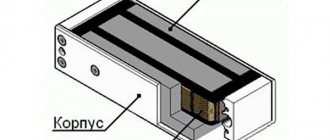
Photo 1. Contents of the Chinese garland controller.
Each color has its own generator, which means they can function separately from each other. However, each of them has its own power level, which makes the flickering process chaotic.
It can be emphasized that when adding white color to the scheme, it will create the impression that the flickering of the colors of the New Year's garlands will occur on a white background.
The peculiarity of New Year's garlands from China is that they are extremely simple and all varieties have the same patterns. Their simplicity is justified by the price of the product, but the quality leaves much to be desired.
Even the minimum price that stores ask for does not justify the real cost of the product. If you evaluate the garland by the elements that are included in it, then the price will not be even 50 cents. It's all about a simple controller that costs a penny. It should be considered in more detail.
Chinese garland controller
If you look from above, it seems that everything is quite simple: an ordinary box with only one button. Having opened that same box, you can find the elements that are shown in photo 1.
Photo 2. Places for soldering wires on the Chinese garland chip.
The controller itself is made in the form of a drop of black solidified substance. There is a control button right next to it. In addition to them, there is an electrolytic capacitor and three outputs for a thyristor.
However, there is a place for a fourth thyristor; when soldered, you can create an additional channel, for example, for the same white color. The channel is also hardwired into the controller, so installing it won't be difficult.
The only point is that with three thyristors, the New Year's garland circuit is even cheaper.
The thyristors, which are included in the circuit of the New Year's garland from China, are quite small in size, while their reverse voltage is 400 V, and the forward current is 0.8 A. With a load of symbolic 25% and a voltage of 220 V, each of them is capable of switching power in 44 W.
It is also necessary to pay attention to the soldering diagram of all contacts. All possible drawings are provided for it
It can be seen in photo 2.
Knowing all these subtleties, you can repair a broken garland or simply expand your knowledge of electronics.
Idea N1. The simplest DIY garland
The simplest option for a garland is lighting made from LED strips. They are suitable both as New Year's decorations and for highlighting the outline of a showcase or interior elements. Their advantage is their flexible design, so you don’t need to solder anything, just glue them to a supporting surface or structure. But moving it like the classic option won’t work.
The simplest models are 220 V - for them you need to solder an electrical plug and install it in the right place. Most often they are used for outdoor installation.
To illuminate Christmas tree decorations indoors, 12 V LED strips are used. These are safer models, but a power supply must be used to connect them.
It is much more difficult to make a garland from RGB tape, since connecting it requires the use of a large number of mechanisms.
The process will include the following steps:
- Calculate the total length of the garland, since the length of the ribbon cannot exceed 5 m. Everything above 5m must be connected from a separate power supply system.
- Install the power supply - it is necessary to lower the voltage to 12V.
- Connect the controller for the RGB strip to the power supply - this device will allow you to select the color of the glow and operating mode.
- If the length is more than 5 m, install the amplifier on the next tape or supply power from another power supply / controller set.
- Attach the RGB strip to the surface and connect to the controller.
You can find out more about the principles of connecting an RGB strip in the corresponding article -
Soviet style garlands
Garlands produced in Soviet times are reliable. Another feature is that they can be repaired, while not all Chinese-made products can be repaired. Modern devices and tools make it possible to identify faults and carry out repair work.
Required set of tools and materials:
- soldering iron;
- indicator screwdriver;
- insulating material;
- pliers.
The garland uses a serial connection circuit. In other words, if one light bulb burns out, the entire system stops functioning.
We check the lamps for integrity. If the light sources are not damaged, check how they are screwed into the sockets. If necessary, screw the lamp into the socket until the end.
Advice! If you need to replace a colored light bulb, but a replacement is not available, it is recommended to paint the light source with tsapon varnish.
If the steps described above do not give a positive result, take an indicator screwdriver and look for the area where the contact is interrupted in the conductor. The broken contact is not necessarily located in the wire, so we also check the cartridge. If the problem is a broken contact, we restore its functionality using a soldering iron. If necessary, we connect the conductors directly.
Possible causes of failure
Before you begin to repair a faulty garland, you need to identify the causes of the problem. The problem may be:
- frayed wires on the plug;
- burnt out lamps;
- blown fuse or circuit itself;
- controller malfunction;
- problems with LEDs;
- broken contact connection with the cartridges.
Some people are not stopped by the burnout of one or two lamps on a garland. The product continues to be used, although it does not look aesthetically pleasing. Moreover, such a problem is easy to fix.
Broken lamps
One or more broken lamps can be easily replaced. The garland is disconnected from the network, the broken parts are removed and new ones are screwed in their place. If you don’t have a new spare part at hand, you can cut off the non-working cartridge and connect the wires. To do this, you will need a utility knife and electrical tape that matches the color of the wires.
The cartridge of the broken part is cut off with a knife. The contacts are stripped of the rubber sheath and the two cut parts are twisted together. The coils are tightly wrapped with insulating tape. The garland is connected to the network and its operation is checked. If the wires are connected correctly, the product should work. If the product will be used for several more years, then it is better to replace all fragile lamps with unbreakable parts.
The whole garland is not lit
In some cases, the garland does not light up completely, although all the lamps are working. Then you need to check the operation of the power cord and control unit. First, check the integrity of the wire - it may be broken or torn. Then inspect the contact connections of the board.
If the contacts and cord are fine, then the problem lies with the board. The control unit can be replaced with a starter from a 220 V fluorescent lamp. It is necessary to check the connection of the LEDs; they can be connected by anodes or cathodes. In the first version, the circuit is completely redone and replaced with a cathode connection. Replacement is mandatory, since normal operation of the starter is ensured by the fact that voltage must be supplied to the anode through a five-watt resistor. Diodes are also connected to the circuit; the reverse mains current passes through them.
This repair method is used if the controller stops working, and also when the lamps do not blink. It is better not to repair the circuit of a cheap Chinese product due to its fragility.
One color doesn't work
In multi-colored products, sometimes certain colors stop working. The cause of this failure is a problem with the color sector. First of all, disassemble the power supply and check the connection of all contacts. If everything is fine with it, then the problem is a burnt out lamp.
In modern products, LEDs of the same color are connected in series, so if one lamp burns out, the entire section stops working. Repairing an LED garland with your own hands is troublesome: you need to cut it in half and check the lamps, then each half is divided into two more parts, and so on until the end of the product until a damaged part is identified.
You can use a tester with needles instead of probes to check the sections. At each section of the circuit, a needle sequentially pierces the current-carrying core and compares the resistance readings. Near a broken lamp, the indicator will differ significantly from the rest. This is how non-removable electrical garlands are repaired.
For Soviet products without a switch box, all LEDs are screwed into separate sockets, so the fault can be found by attaching a working part to each socket. A tester also helps to find the burnt-out area; they measure the resistance of each light bulb.
Idea N4. Garland of LEDs
To do this, you will need a soldering iron, solder, rosin, LEDs, connecting wires (even thin power cords will do), plug or battery, power supply, button or switch. In this example, we will consider making a battery-powered garland.
- Solder the power wires to the contacts in the power supply housing for the batteries.
- Solder the LEDs to the wires, but be sure to keep in mind that the voltage applied to one LED should not exceed its rated voltage, so when connecting diodes in series, a resistor must be included in the LED power circuit.
Figure 11: LED connection
The resistance of the resistor is calculated in such a way as to reduce the voltage drop across the LED to the nominal value.
- Repeat the same procedure with the remaining LEDs.
- Solder the switch to the battery power supply.
Rice. 12: Solder the switch - Connect the LEDs to the power supply and insert the batteries into the block. If they do not hold, you can wrap the battery with tape or secure it with an elastic band, the garland is ready.
Ready-made LED garland
Tips for Repairing Chinese New Year Garlands
Although the price of garlands is low, sometimes situations arise when you have to repair them. And there are not many opportunities here. Next, we will talk about simple methods for repairing Chinese New Year garland.
Tips for operation and repair are usually given in abundance on the back of the beautiful packaging box. The process of replacing light bulbs is described in great detail, although there are no spare ones included. There are also a lot of safety warnings and instructions for using the garland.
One of the wonderful properties of such garlands is that after lying on a shelf until the next New Year, they most often do not want to light up, and they have to be repaired. Figure 1 will help explain how to do this.
All malfunctions of such garlands come down to three types: broken wires, loss of contact in the sockets, burnt out lamps. After you have crushed the garland in your hands, shook it, felt all the cartridges, quarreled with obscene words and achieved no results, you have to get down to business seriously.
To facilitate the procedure, the garland should be laid out on the floor, literally, as shown in Figure 1, and instrumental measurements should be taken. But first, lightly tug on the wires, it will suddenly fly out of the socket, try to tighten the light bulbs a little.
This is best done with the garland on, but don’t get too carried away, as you won’t crush the bulbs. Otherwise, you might just get an electric shock! The method is unsafe, but quite effective and efficient.
Figure 1. An example of repairing a New Year's garland
If these actions did not help, and the garland did not light up, then you will have to move on to instrumental measurements. First, “ring” the upper and lower (as in the picture) halves of the garland with a multimeter. Ring the half that turns out to be faulty several more times, each time reducing the length of the measured section by exactly half. This will greatly reduce the number of attempts. Such is the magical power of the number two.
To check how magical it is, try folding a notebook or A4 sheet of paper in half ten times. You can even bend a whole newspaper, but it still won’t work, because two to the tenth power is 1024! This is exactly how many layers there should be in a folded sheet of paper. Therefore, you can argue with anyone about this “intellectual” exercise even on New Year’s Eve. All the same, victory will be yours. If you don't believe me, try it right now!
But, before “ringing” the entire garland with a multimeter, you should make sure that the wiring has not broken off right next to the outlet of the power plug. This is a fairly common defect, and not only in garlands, but in almost all plugs, especially with one-time sealing.
After the faulty “half” is found, all that remains is to check the light bulbs and soldering in the lamp sockets. Due to time and high temperature, the soldering simply oxidizes, or the wires break off, but they are quite thin, and here you go, repairs.
It happens that the microcontroller of the New Year's garland itself fails, and it is clear that there is nothing to replace it with. It happens that the output thyristors explode, leaving black spots of soot on the board.
Thyristors can be changed, fortunately, they are sold on radio markets and online stores. The issue price is 13 rubles per piece. And this is with the price of a new garland being 38 rubles! Although, in fairness, it should be noted that there are similar garlands that are much more expensive. So all repair possibilities come down to finding broken wires, as described above.
Sampler for repairing garlands
Checking with a multimeter is undoubtedly good, but poking the probes of the device through the insulation of the wires is a thankless task. Probes specially created for this purpose will help speed up the troubleshooting process. The diagram of one of them is shown in Figure 2.
Figure 2. Diagram of a probe for repairing garlands
Working with the probe is very simple. You need to start with the wire of the garland that is included in the phase. In this case, if the antenna WA1 is subjected to an electric field, a high-pitched sound is emitted from the speaker BF1. When the antenna passes the break and moves to the side of the neutral wire, the squeaking in the speaker stops.
Here, as they say, options are possible. If you start with the neutral wire, then after a break in the garland, the phase wire will fall under the antenna, and naturally, sound will appear. The BF1 speaker uses a DEM-4M capsule or a similar one with a coil resistance of 100…200Ω. Similar capsules are used in telephone sets.
Boris Aladyshkin
Idea N2. Flashing LED strip garland
Direct connection of a white LED strip is a little-used garland option, since there is only one glow mode. But with a certain addition, it can be significantly upgraded by changing the mode from the usual light bulb to flashing. To do this, you will need an LED strip, an RGB controller, a remote control for the controller, and a power supply.
- Divide the LED strip into three sections (they will blink in different sequences). The minimum area is the distance between the markings for the cut. Separation of sections is carried out along the negative bus in specially designated areas, as shown in the figure:
Rice. 3: Cut out the pad - Repeat the same procedure with the remaining two sections. In this example, each section includes three LEDs. When cutting out the pad, it is important to break the electrical connection between the LED legs.
Rice. 4: tape divided into three sections - Take four different colored wires, strip the ends and tin them.
Rice. 5: Tin the ends of the wires - Apply tin to the contacts of the tape as shown in the picture.
Rice. 6: apply tin to the contacts of the tape - Using a soldering iron, solder wires to the contacts of the tape.
Rice. 7. Solder the wires to the contacts on the tape - Tie the wires from the contact pads and from the edge behind the tape; in addition, they can be organized with tape or adhesive tape.
Rice. 8: Organize your wires - Strip the wires and connect the tape leads to the RGB controller using a terminal block.
Rice. 9: Connect the ribbon to the controller
The garland is ready, connect it to the network via the power supply and you can enjoy the flashing lights. Using the controller's remote control, you can switch the garland to different modes (blinking, alternating blinking of sections and other options).
Ready-made LED strip with running lights
Schemes of New Year's garlands
Serial connection of paws
First, let's look at the simplest scheme of a New Year's garland. This series connection of incandescent light bulbs was the most common scheme in the Soviet years. Every house had a similar garland.
In a series connection, all the light bulbs are connected in a chain, in a wire break, and connected to a power source, generator, home wiring, battery. In this case, the same current flows throughout the garland.
There was no smell there, of course. She was forced to blink by starters taken from fluorescent lamps at school. The starters were simply connected in a circuit, similar to light bulbs, in series.
A few words about starters and their meaning. This is a simple gas-discharge lamp placed in an aluminum, paper or plastic housing. For convenience, an inspection hole is made in the body.
It consists of two bimetallic electrodes, which, bending from the passing current, close and open the electrical circuit. After that, the New Year's tree garland began to blink quite quickly.
This scheme is very simple and convenient, but has a significant disadvantage. When one light bulb burns out, the electrical circuit is broken and the entire garland goes out.
Parallel connection
Modern Chinese Christmas tree garlands are included in a parallel electrical circuit. By doing this, they extend the service life of the garland and delay repairs for a long time.
The whole point is that when the bulbs in a Christmas tree garland are connected in parallel, the voltage remains the same on each element of the circuit. Which gives a lot of advantages, the main thing is that if any light bulb in the circuit burns out, it does not break and the garland continues to work. As for the current strength, it is different for each element of the circuit.
This scheme is the most common in home electrical wiring, due to its reliability, convenience and simplicity.
The main malfunctions of New Year's garlands
Let's simulate the situation: you take out your Christmas tree decorations and New Year's garlands from the closet, start decorating the tree, turn it on, and nothing happens. Disappointment and despair on the faces of your children, faith in New Year's magic disappears, the holiday was not a success.
It is still possible to fix everything, even if there is a delay of fifteen minutes before the chiming clock, using your own strength and a simple tool.
The garland shows no signs of activity at all. We look at the electrical plug, its integrity is called a device. To do this, we disassemble the control unit of the Chinese garland, and look at the contacts that come from the electrical plug.
Idea N5. Retro garland
Retro garlands are popular when decorating photo zones, terraces, gazebos, shop windows and other objects. And it is not at all necessary to purchase a finished product, since anyone can assemble it. To do this, you will need: a connecting wire (it’s a good idea to get wires in fabric insulation), sockets (the most convenient models with clamps for wires), the incandescent light bulbs themselves (you can also take LED ones), a plug and a switch. In this example, we will consider a series connection of light bulbs; we will use some sockets with a built-in switch.
- Cut the wires into pieces of the required length - they will determine the distance between the glow points.
Rice. 13: cut the wires into pieces - Strip the insulation of the wires at the ends; in these places they will be connected to the cartridge, so the length of the core must be appropriate.
Rice. 14: Strip the ends of the wires - If you are using a wire with fabric insulation, then its edge must be fixed with electrical tape so that the fabric does not fray further.
Rice. 15. Secure the insulation with electrical tape - Disassemble the cartridge itself and thread the wires into the cartridge cover.
Rice. 16: insert the wires into the socket cover - Connect the ends of the wires to the contacts of the cartridge
Rice. 17: Connect the wires to the socket - Assemble the cartridge body; the excess length of wires from under the cover should be carefully pulled out, avoiding excessive force, so as not to loosen the contact.
Rice. 18: Assemble the chuck body - Repeat the same procedure with the remaining sockets, after which you can fix the light bulbs in them.
- Cut the wire from the last light bulb; you will need one core from it, which you need to connect to the switch gap.
Rice. 19: Connect the switch - Connect the edges of the wire to the plug; to do this, they must be inserted into the groove of each contact and clamped with a screwdriver. Arrange the rest of the wire so that it does not protrude; the plug body should close normally.
Rice. 20: connect the edges of the wire to the plug
The retro garland is ready for use - plug in and enjoy. If you wish, you can complement the garland’s surroundings with a darkened wire or socket - they can be painted in the appropriate color. For greater gloss, the wires are painted with gold or bronze paint.
Ready-made retro-style garland of light bulbs
Diagram of a classical Chinese garland
This design is equipped with smooth brightness control. For this, phase control is used to regulate the opening angle of the thyristors. Automation uses as many as eight programs that provide a wide variety of control algorithms. Due to its qualities, the device is very cheap, which is why it sells in millions of copies.
The controller is based on a small board with space provided. A microcontroller with four outputs is also located here. It is a small piece of genitax, where a microchip is attached using epoxy resin. Through the outputs of the microcontroller, using current-limiting resistors, four thyristors are controlled. This device is designed for anode voltage up to 600 volts and a current in the range of 0.6-0.8 amperes. In some designs of cheap garlands, instead of the input diode bridge, one diode remains. At the same time, the electrodes that control the thyristors are connected directly to the microcontroller outputs, without limiting the current.
As a rule, the power of the microcontroller is very small, therefore, it is not able to control the operation of powerful triacs. In order to solve this problem, it is necessary to use a separate low-power power source that is galvanically isolated from the general network. For these purposes, you can use a low-power adapter, for example, one that powers a television antenna amplifier that contains a stabilizer in its circuit.
Read with this
- Electric garland
- Garland meteor shower
- Comparative analysis of LED and incandescent lamps
- LED tube lamps 9 and 18 W, length 600 and 1200 mm
- How to install light in a steam room?
- Why is the LED lamp blinking?
- LED lamps: warm light or cold, what’s the difference?
- Fluorescent lamps: parameters, device, circuit, pros and cons compared to others
- White spots from incandescent lamp
- LED Color Temperature Chart