Basic requirements for devices
In order for the device to be successfully operated, it must meet the following requirements:
- In no case should protection devices have a temperature exceeding that permissible for them under normal load of the electrical network or electrical equipment.
- The device should not disconnect the equipment from the power supply during short-term overloads, which often include inrush current, self-starting current, etc.
When choosing fuse links for fuses, it is necessary to base the rated current in the section of the circuit that will protect the device. This rule for choosing protective devices is relevant in any case when choosing any device for protection. It is also important to understand that with prolonged overheating, the protective qualities are significantly reduced. This has a negative impact on the devices, since at the moment of critical load they may, for example, simply not turn off, which will lead to an accident.
Protection devices must necessarily turn off the network when prolonged overloads occur within this circuit. In this case, the inverse dependence on the current with respect to the holding time must be observed.
In any case, the protective device must disconnect the circuit at the end when a short circuit (short circuit) occurs. If a short circuit occurs in a single-phase circuit, then the shutdown must occur in a network with a solidly grounded neutral. If a short circuit occurs in a two-phase circuit, then in a network with an isolated neutral.
Electrical circuit protection devices have a breaking capacity of I pr. The value of this parameter must correspond to the short circuit current that may occur at the beginning of the protected section. If this value is lower than the maximum possible short-circuit current, then the process of disconnecting a section of the circuit may not occur at all or may occur, but with a delay. Because of this, not only the devices connected to this network can be damaged, but also the electrical circuit protection device itself. For this reason, the breaking capacity factor must be greater than or equal to the maximum short-circuit current.
What is IP protection degree
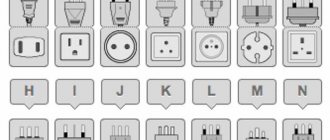
Much electrical equipment and some other electrically powered devices have an enclosure that protects against the penetration of solid objects/dust and water/moisture. The degree of this protection is checked during tests, the results are displayed in the form of two numbers that follow the Latin letters IP.
IP - International Protection Marking (translated from English - “international protection codes” ). Sometimes interpreted as Ingress Protection Rating - the degree of protection against penetration (of body parts such as hands and fingers), dust, accidental contact, water, etc.
The numbers following the letters IP indicate the degree of security. The first number shows how much the case protects the “insides” from dust or other large objects. The second is the degree of protection from moisture (water jets, splashes and drops).
General form of recording the protection class of electrical equipment
In some cases, this formula is supplemented with two Latin letters that describe auxiliary characteristics. This part is optional and only appears in certain situations.
The IP protection degree is important when choosing electrical appliances (lamps, heaters, etc.) and electrical installation products (sockets, switches) that will be used in conditions of high humidity (bathrooms, baths, saunas, swimming pools, etc.) and/ or in places with a lot of dust (installation on the street, in a garage, in a workshop, etc.).
Fuses
Today there are several devices for protecting electrical networks, which are the most common. One such device is a fuse. The purpose of a protection device of this type is that it protects the network from current overloads and short circuits.
Today, there are devices for one-time use, as well as with replaceable inserts. Such devices can be used both for industrial needs and in everyday life. For this purpose, there are devices that are used in lines up to 1 kV.
In addition to them, there are high-voltage devices used at substations whose voltage is more than 1000 V. An example of such a device would be a fuse on auxiliary transformers of substations with 6/0.4 kV.
Since the purpose of these protection devices is to protect against short circuits and current overloads, they are widely used. In addition, they are very simple and easy to use, their replacement is also quick and easy, and they themselves are very reliable. All this has led to the fact that such fuses are used very often.
To review the technical characteristics, you can take the PR-2 device. Depending on the rated current, this device is available with six types of cartridges, which differ in diameter. In the cartridge of each of them, an insert can be installed with the expectation of a different rated current. For example, a cartridge designed for a current of 15 A can be equipped with an insert for both 6 A and 10 A.
In addition to this characteristic, there is also the concept of lower and upper test current. As for the lower value of the test current, this is the maximum value of current, when flowing in the circuit for 1 hour, a section of the circuit will not be disconnected. As for the upper value, this is the minimum current coefficient that, when flowing for 1 hour in the circuit, will melt the insert in the protection and control device.
Levels of protection for electrical appliances
It is not surprising that today more and more devices connected to the electrical network are equipped with high-quality protection.
Mainly, such protection of electrical appliances, which can consist of one or several levels, and from a technical point of view can be implemented differently in different devices, guarantees automatic disconnection from the power source in the event of a short circuit, protecting subnetwork equipment from damage, and the electrical appliance from heating and ignition.
As the complexity of the protected device increases, so does the functionality of its protective mechanisms. For example, there are voltage stabilizers.
But such devices are quite an expensive luxury nowadays, although if you think logically, then, for example, a plasma TV costs a lot more.
Simple and at the same time popular examples are fuses that are familiar to everyone, as well as current control relays, which are less familiar to ordinary citizens.
Circuit breakers
Circuit breakers play a similar role to fuses, but their design is more complex. However, this is compensated by the fact that switches are much more convenient to use than fuses. For example, if a short circuit occurs in the network due to aging insulation, the switch is able to disconnect the damaged section of the electrical circuit from power. At the same time, the control and protection device itself is quite easily restored; after operation it does not require replacement with a new one, and after repair work it is again able to reliably protect the section of the circuit under its control. It is very convenient to use this kind of switches if you need to carry out any routine repair work.
As for the production of these devices, the main indicator is the rated current for which the device is designed. In this regard, there is a huge selection, which allows you to select the most suitable device for each circuit. If we talk about operating voltage, then they, like fuses, are divided into two types: with voltages up to 1 kV and high-voltage with operating voltages above 1 kV. It is important to add here that high-voltage devices for protecting electrical equipment and electrical circuits are produced vacuum, with inert gas or oil-filled. This design allows the chain to be released at a higher level when the need arises. Another significant difference between circuit breakers and fuses is that they are manufactured for operation not only in single-phase, but also in three-phase circuits.
For example, if a short circuit to ground occurs in one of the cores of an electric motor, the circuit breaker will turn off all three phases, and not just the damaged one. This is a significant and key difference, since if only one phase is turned off, the motor will continue to operate on two phases. This mode of operation is emergency and greatly reduces the service life of the device, and can even lead to emergency failure of the equipment. In addition, automatic type switches are manufactured to operate with both alternating and direct voltage.
Selection of electrical equipment by degree of protection
We select electrical equipment according to the degree of protection:
Before you begin any installation of electrical equipment, you need to determine the degree of protection of electrical equipment in accordance with PUE, GOST, TU, i.e. under what conditions will the electrical equipment operate (outdoors, indoors, at what temperatures, etc.):
- First, let's look at the PUE - Electrical Installation Rules (7th edition Chapter 1.1.), which states:
General instructions for electrical installations
1.1.19. Electrical equipment, electrical products and materials used in electrical installations must comply with the requirements of state standards or technical specifications approved in the prescribed manner.
1.1.20. The design, design, installation method, class and insulation characteristics of the machines, devices, instruments and other electrical equipment used, as well as cables and wires, must comply with the parameters of the network or electrical installation, operating modes, environmental conditions and the requirements of the relevant chapters of the PUE.
1.1.21. Electrical installations and associated structures must be resistant to or protected from environmental influences.
- International standard IEC 60529 ( DIN 40050), and GOST 14254-96:
The standard applies to electrical products with voltages not exceeding 72.5 kV and establishes the degrees of protection provided by enclosures. The degrees of protection of electrical products are indicated by the symbol: IP 11, where IP are the initial letters: International Protection (translated from English as the degree of protection against penetration) - a system for classifying the degrees of protection of the enclosure of electrical equipment from the penetration of solid objects and water; the first digit is a characteristic of personnel protection from contact with live parts or approaching them and from contact with moving parts located inside the enclosure and entry of solid foreign bodies; the second digit is the characteristic of protection against water penetration. If the product requires the degree of protection to be indicated in only one digit, then the missing digit is replaced with the letter X, for example IPX5, IP2X, etc. Degrees of protection of electrical machine shells: IP00, IP01, IP 10, TRI, IP12, IP13, IP20, IP21, IP22, IP23, IP43, IP44, IP54, IP55, IP56. Degrees of protection of power transformers (autotransformers) and electrical reactors designed for operation in electrical devices and alternating current networks with a frequency of 50 Hz: 1Р00, IP10, IP11, IP13, IP20, IP21, IP22, IP23, IP30, IP31, 1Р32, IP33, IP34 , IP41, IP43, IP44, IP54, IP55, IP65, IP66. Degrees of protection of electrical apparatus shells up to 1 kV: IP00, 1Р10, 1Р11, IP12, IP20, IP21, IP22, IP23, 1Р30, 1Р31, 1Р32, IP33, IP34, IP40, IP41, IP42, IP43, IP44, IP50, IP51, IP54 , IP55, IP56, IP00, IP65, IP66, IP67, IP68.
The first number is protection against penetration of foreign objects:
Protection against foreign objects having a diameter
Source: energetik.com.ru
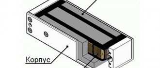
Thermal and current relay
Today, among electrical network protection devices there are many different types of relays.
A thermal relay is one of the most common devices that can protect electric motors, heaters, and any power devices from problems such as overload current. The operating principle of this device is very simple, and it is based on the fact that electric current is capable of heating the conductor through which it flows. The main working part of any thermal relay is a bimetallic plate. When heated to a certain temperature, this plate bends, which breaks the electrical contact in the circuit. Naturally, the plate will heat up until it reaches a critical point.
In addition to thermal ones, there are other types of protection devices, for example a current relay, which controls the amount of current in the network. There is also a voltage relay that will respond to changes in voltage in the network and a differential current relay. The last device is a leakage current protection device. It is important to note here that circuit breakers, like fuses, cannot react to the occurrence of current leakage, since this value is quite small. But at the same time, this value is quite enough to kill a person upon contact with the body of a device susceptible to such a malfunction.
If there are a large number of electrical devices that need to be connected to a differential current relay, then combined circuit breakers are often used to reduce the size of the power panel. Such devices are devices that combine a circuit breaker and a differential current relay - differential protection circuit breakers, or differential circuit breakers. When using such devices, not only the size of the power shield is reduced, but also the process of installing the protection device is greatly simplified, which, in turn, makes them more economical.
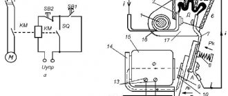
A little history
The simplest device for these purposes was a control unit with a low-power three-phase transformer connected to the corresponding phases of the network. A rectifier assembled according to A.N.’s circuit was connected to the output of the transformer. Larionov, a relay was switched between its positive and negative terminals. If any phase of the network breaks, the specified relay disconnects the consumer from the network.
They were replaced by devices with so-called network action logic. Analysis of the PKE of 0.4 kV distribution networks showed that the most common type of network voltage accident, in addition to the above-mentioned phase failure, is changes in the sequence, phase sticking caused by accidents at substations or in the network itself, phase imbalance, deviations, voltage surges and dips. To control these types of accidents, relays began to be used, used in automation circuits of high-voltage networks, operating according to a similar algorithm. But, functionally, relays originally created for installation in distribution substations were not entirely suitable for full voltage protection. The consumer had to put up with what was there, or install not one, but several devices.
Characteristics of thermal relay
The main characteristic for thermal relays is the response time, which depends on the load current. In other words, this characteristic is called time-current. If we consider the general case, then before the load is applied, current I0 will flow through the relay. In this case, the heating of the bimetallic plate will be q0. When checking this characteristic, it is very important to consider from what state (overheated or cold) the device is triggered. In addition, when testing these devices, it is very important to remember that the plate is not thermally stable when a short circuit current occurs.
Thermal relays are selected as follows. The rated current of such a protective device is selected based on the rated load of the electric motor. The selected relay current should be 1.2-1.3 of the rated motor current (load current). In other words, such a device will work if the load is between 20 and 30% within 20 minutes.
It is very important to understand that the operation of the thermal relay is significantly influenced by the ambient air temperature. Due to an increase in ambient temperature, the operating current of this device will decrease. If this indicator differs too much from the nominal value, then it will be necessary to either carry out additional smooth adjustment of the relay, or buy a new device, but taking into account the actual ambient temperature in the working area of this unit.
To reduce the influence of ambient temperature on the magnitude of the current operation, it is necessary to purchase a relay with a large rated load value. In order to achieve proper functioning of the warm device, it should be installed in the same room in which the controlled object is located. However, you need to remember that the relay reacts to temperature, and therefore it is prohibited to place it near concentrated heat sources. Such sources are considered to be boilers, heating sources and other similar systems and devices.
Device selection
When choosing equipment to protect electrical receivers and electrical networks, it is necessary to base it on the rated currents for which these devices are designed, as well as on the current supplying the network where such units will be installed.
When choosing a protective device, it is very important to keep in mind the occurrence of such abnormal operating modes as:
- short circuits of phase-to-phase type;
- phase short circuit to housing;
- a strong increase in current, which can be caused by an incomplete short circuit or overload of process equipment;
- complete disappearance or too much reduction in voltage.
As for short circuit protection, it must be carried out for all electrical receivers. The main requirement is that disconnecting the device from the network when a short circuit occurs should be the minimum possible. When choosing protective devices, it is also important to know that full overcurrent protection must be provided, with the exception of the following few cases:
- when overloading electrical receivers for technological reasons is simply impossible or unlikely;
- if the power of the electric motor is less than 1 kW.
In addition, the electrical installation protection device may not have an overload protection function if it is installed to monitor an electric motor that is operated in short-term or intermittent mode. An exception is the installation of any electrical appliances in rooms with a high fire hazard. In such premises, overload protection must be installed on all devices without exception.
Undervoltage protection must be installed in a number of the following cases:
- for electric motors that cannot be connected to the network at full voltage;
- for electric motors in which self-starting is not allowed for a number of technological reasons, or it is dangerous for employees;
- for any other electric motors, the power off of which is necessary in order to reduce the total power of all connected electrical receivers in this network to an acceptable value.
Power quality indicators
Unified requirements for the electromagnetic environment are established by standards, which makes it possible to create equipment and guarantee its performance in conditions that meet these requirements. The standards establish acceptable levels of interference in the electrical network, which characterize power quality (PQ) and are called power quality indicators (PQI). Requirements for the quality of electrical energy on the territory of the Russian Federation are determined by the Interstate Standard: “Electric Energy. Electromagnetic compatibility of technical equipment. Standards for the quality of electrical energy in general-purpose power supply systems"\ GOST 13109-97. The main indicators of the quality of electrical energy determined by this GOST include:
- voltage deviations associated with the load operating schedule;
- voltage fluctuations with sharply changing load patterns;
- voltage asymmetry in a three-phase system with asymmetric load distribution across phases;
- non-sinusoidal shape of the voltage curve under nonlinear load;
- deviation of the actual frequency of alternating voltage from the nominal value in the steady state of operation of the power supply system; Voltage dips - a sudden and significant decrease in voltage (less than 90% Un) lasting from several periods to several tens of seconds, followed by voltage restoration;
- temporary overvoltages - a sudden and significant increase in voltage (more than 110% Un) lasting more than 10 milliseconds;
- pulse overvoltage - a sharp increase in voltage lasting less than 10 milliseconds, reaching thousands of volts.
GOST establishes two types of standards for PKE: normal permissible and maximum permissible. Let us consider, using the example of voltage deviation from nominal values, what threatens electrical equipment if it exceeds the permissible values (see Table No. 1)
GOST establishes normal and maximum permissible values of steady-state voltage deviation at the terminals of electrical receivers within the limits, respectively, ?Uynorm= ± 5% and ?Uylim= ± 10% of the rated network voltage.
Table No. 1. Effect of voltage deviation on electrical equipment
| Electrical equipment | Reduction by 10% from Un | Excess by 10% of Un |
| Asynchronous electric motors The motor torque varies proportionally to the square of the voltage | Engine torque is reduced by 19%. The temperature rises by 7°C. Start-up time increases. Slip increases by 27.5%, rotor current by 14%, stator current by 10%. | Increased engine torque causes overload of shafts and belt drives, and the starting shock increases. Starting current increases by 12%, torque by 21%, power factor decreases by 5%. |
| Lighting devices (incandescent lamps, fluorescent, infrared, mercury, gas-filled, ballast resistors, starters, capacitors) The service life of incandescent lamps varies in proportion to the voltage to the power of 13.1, luminous efficiency - 3.4, light output per 1 kW-hour - to the power of 1 , 8 | For normal lighting, 30% more incandescent lamps will be required, and 15% more fluorescent lamps. Luminous flux is reduced by 10%. | The service life of incandescent lamps is reduced by 2.5 times. The temperature of ballast resistances increases, infrared light sources increase heat generation by 21%. |
| Electronic equipment The service life of electronic components is reduced by 4 times. Digital errors occur. The software fails. | Thyratrons fail within minutes | Surge filters, power supplies, adapters burn out |
It is obvious that operating electrical equipment, even within acceptable limits, not only significantly reduces its service life and reduces operating efficiency, but often leads to its failure. And if we take into account that in our domestic networks, as one responsible power engineer puts it, there is a real “vinaigrette”, then the PCE going beyond acceptable limits is, unfortunately, an everyday reality.
Types of currents and selection of protective devices
The most dangerous is short circuit current. The main danger is that it is much higher than the normal inrush current, and its value can vary greatly depending on the section of the circuit where it occurs. Thus, when checking a protective device that protects a circuit from a short circuit, it must disconnect the circuit as quickly as possible when such a problem occurs. Moreover, in no case should it be triggered when a normal value of the starting current of any electrical device occurs in the circuit.
As for the overload current, everything is quite clear here. Such current is considered to be any characteristic value that exceeds the rated current of the electric motor. But here it is very important to understand that not every time an overload current occurs, the protective device must disconnect the circuit contacts. This is also important because short-term overload of both the electric motor and the electrical network is acceptable in some cases. It is worth adding here that the more short-term the load, the greater values it can reach. Based on this, it becomes clear what the main advantage of some devices is. The degree of protection of devices with a “dependent characteristic” in this case is maximum, since their response time will decrease with increasing load factor at this moment. Thus, such devices are ideal for overcurrent protection.
To summarize briefly, we can say the following. For short-circuit protection, a fast-moving device must be selected, which will be configured to operate at a current that is significantly higher than the starting value. To protect against overload, on the contrary, the protection switching device must have inertia, as well as a dependent characteristic. It must be selected in such a way that it does not operate while the electrical device is normally starting.
▍Act three. Semiconductors protect semiconductors.
Varistors have come to replace arresters in protecting lines (and not only power lines, but also, for example, communication lines, but the post is mainly devoted to power lines with a voltage of 220-230V). These are a special type of resistor whose resistance depends on the applied voltage. This is what their current-voltage characteristic looks like, which shows the relationship between the current through the device and the applied voltage:
Source
That is, they behave approximately
like arresters. If the voltage is below the threshold, then their resistance is high, there is only a tiny leakage current. If the voltage exceeds the threshold, then the varistor changes its resistance quite significantly, beginning to conduct current well. But, unlike a spark gap, it returns to its original state with high resistance as soon as the voltage drops below the threshold. As a result, the voltage at the varistor contacts turns out to be relatively stable; it will compensate for the increase in voltage by increasing the current through itself, which will prevent the voltage from rising.
Purely technically, a varistor is a sintered ceramic tablet made of a substance that has the properties of a semiconductor, for example, zinc oxide granules in a matrix of a mixture of metal oxides, which is why it is called MOV - Metal Oxide Varistor. The granules create a huge number of pn junctions that conduct current in one direction. But since there are many of them and in a random order, they are useless for rectifying current. But the property of causing an electrical breakdown when a certain voltage is exceeded (and the electrical breakdown of the pn junction is reversible) turned out to be very useful. By adjusting the thickness of the tablet, it is possible to achieve a fairly stable threshold voltage during production. And by increasing the volume of the washer, you can increase the maximum pulse energy that the varistor can absorb.
The varistor turned out to be not ideal, so it did not replace, but only supplemented the arresters. For the huge advantage - the absence of a difference between the breakdown voltage and the recovery voltage, varistors are forgiven for leakage currents, limited service life (after a certain number of operations they can lose characteristics), large size with modest permissible discharge energies. A varistor connected to the line will dampen voltage surges approximately as follows:
Since a varistor can become unusable over time, and for example, begin to conduct current when it is not required, causing a short circuit, it is necessary to provide protection against short circuits. Large, powerful varistors on a DIN rail, for protecting power lines, often contain built-in protection. For example, this is what the filling of a varistor in a panel from IEK looks like:
You can see the varistor tablet itself (blue). Electrodes are attached to it and a spring-loaded flag rests on an electrode soldered with low-melting solder... If the varistor heats up beyond a reasonable level (no matter from an incoming pulse from lightning, or due to degradation), then the solder melts, the electrode is disconnected, breaking the circuit, and the spring lowers the flag, indicates a varistor fault. If protection is not provided, uncontrolled heating of the varistor can be caused by a fireman.
Small varistors can be found in many electronic devices to protect against high voltage surges that accidentally come through the network. In most extension cords that call themselves “surge protectors,” all filtering comes down to the presence of a pair of varistors inside. Here in the photo you can see varistors (blue) in different extension cords:
Disadvantages of different types of protective devices
Fuses, which were previously widely used as devices for protecting switchgear, have the following number of disadvantages:
- rather limited possibility for use as protection against overload current, since detuning from inrush currents is quite complicated;
- the electric motor will continue to operate on two phases, even if the third is cut off by the fuse, which is why the motor often fails;
- in certain cases the cut-off power limit is insufficient;
- There is no way to quickly restore power supply after a power outage.
As for air type circuit breakers, they are more advanced than fuses, but they are not without drawbacks. The main problem with using electrical protective devices is that they are not selective in terms of action. This is especially noticeable if an unregulated cut-off current occurs at the installation machine.
There are automatic installation machines in which overload protection is carried out using thermal releases. Their sensitivity and delay are worse than those of thermal relays, but at the same time they act on all three phases at once. As for universal automatic machines for protection, here it is even worse. This is justified by the fact that only electromagnetic releases are available.
Magnetic starters with built-in thermal relays are often used. Such protective equipment is capable of protecting an electrical circuit from overload current in two phases. But since thermal relays have a large inertia, they are not able to provide protection against short circuits. If you install a holding coil in the starter, you can provide undervoltage protection.
High-quality protection from both overload current and short circuit can only be provided by inductive relays or electromagnetic relays. However, they can only operate through a disconnecting device, which makes their connection circuit more complex.
To briefly summarize the above, we can draw the following two conclusions:
- To protect electric motors, whose power does not exceed 55 kW, from overload current, magnetic starters with fuses or with air devices are most often used.
- If the power of the electric motor is more than 55 kW, then electromagnetic contactors with air devices or protective relays are used to protect them. It is very important to remember here that the contactor will not allow the circuit to break if a short circuit occurs.
When selecting the right device, it is very important to calculate the protection devices. The most important formula is the calculation of the rated current of the motor, which will allow you to select a protective device with suitable indicators. The formula looks like this:
Iн=Рдв ÷(√3*Un*cos c*n), where:
Iн is the rated current of the motor, which will have the dimension in A;
Rdv is the engine power, which is represented in kW;
Un is the rated voltage in V;
cos c is the active power factor;
n is the efficiency factor.
Knowing these data, you can easily calculate the rated current of the motor, and then easily select a protective device suitable for its intended purpose.
Residual current device (RCD) and differential circuit breaker (DA)
An RCD is a residual current device that is controlled by residual (differential) current. It is a switching device (or a set of elements), which, when the residual current exceeds a specified value, must open the contacts and turn off the power supply line.
Now - in more detail. The residual current device is designed to protect a person from electric shock and leakage currents that can cause a fire.
The use of RCDs is necessary, because every day the number of electrical equipment and household appliances is growing exponentially, as is the number of people injured by electric current.
To begin with, it is worth considering the concept of differential current. It comes from the English “different” - different, different. We call it electric leakage current. Let's take a two-core cable as an example. Current flows through one core of the cable and returns through the second. Therefore, in the absence of leakage current, the load current difference between the two cable cores will be zero. This is precisely what the work of the RCD is based on. That is, if a person touches a live line, part of the current will flow through him into the ground (differential current flow). Moreover, not only a person can be an electrical conductor for leakage current (for example, increased humidity in the room due to insulation failure or breakdown). And if an RCD is installed in the system, then its differential transformer will track the change in the current difference in the conductors and turn off the circuit. This will save a person or the power line from overheating.
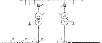
The RCD connection and operating principle are shown schematically in Figure 10.
Rice. 10. Inclusion of an RCD in the circuit and principle of operation
The load current passes through the differential transformer. The non-zero difference that appears in the veins is recorded by the tracking device, which also turns off the solenoid (which no longer holds the contacts in the closed position). The circuit opens and the power line is turned off. Shutdown occurs in a fraction of a second (on average this value is 0.003 s). As an example, I will give an RCD from Siemens AG 5SM3416-8 (Figure 11).
Rice. 11. Appearance of RCD 5SM3416-8
There are many types of RCDs. Of these, two main types can be distinguished (A, AC). AC type RCDs are triggered only by alternating leakage current. Type A RCDs operate on both alternating and direct leakage currents (which is why they are more expensive). Figure 11 shows a type A residual current device. It is worth buying an RCD based on the equipment used. If for a home where household appliances use both direct and alternating current, then the choice should certainly be made in favor of type A.
All descriptions of the main characteristics (rated operating voltage, load currents, core diameter, operating temperature, dimensions, number of connected poles, etc.) of the residual current device are already given above, in the AB characteristics.
Some additional characteristics for the 5SM3416-8 RCD are summarized in Table 2 for clarity.
Table 2. Additional characteristics of the RCD 5SM3416-8
| Rated differential current, mA | 100 |
| Impulse strength, kA | 5 |
| Climatic resistance according to IEC 60068-2-30 | 28 |
| Dimensions, mm | 90x36x70 |
| Rated voltage, V AC | 230 |
| Average number of switchings at rated load | 10000 |
Additionally, the rated differential current is indicated (shows the permissible change in the load current difference on the cores) and impulse strength (the magnitude of the current pulse at which the RCD remains operational).
For reference: sometimes the description may indicate the rated frequency (the frequency value for which the RCD is designed to operate).
RCD in its pure form is not very widespread, since it does not protect equipment and itself from short circuits and overloads in the network. Therefore, the RCD is used in conjunction with a circuit breaker - this combination of devices is called a differential circuit breaker.
To install RCDs and AVs, a special busbar is required so that the continuous connection of the power supply line cores is not disrupted.
The joint normal operation of series-connected RCDs, AVs and their interaction in case of emergency situations is called selectivity. It is necessary so that in the event of an emergency, exactly the device that is needed is activated, and not, for example, the entire line is turned off. This must be taken into account with a complex device connection system (Figure 12).
Rice. 12. Example of complex connection of RCD, AV and loads
This topic is complex; it requires not only knowledge and calculations, but also the use of certain equipment. First of all, it is necessary to ensure current selectivity, which is achieved by installing an AB with a maximum current cutoff at the beginning of the power supply line (usually the releases are adjusted). Those. The power line for all equipment is turned off last. The same purpose is served by time selectivity, where the maximum response time is also adjusted on the supply side.
It is also worth noting that sometimes modular AVs are not so accurate in practice, because The calibration of thermal releases was carried out at room temperature, and the temperature in the room in which the AV operates can be either lower or higher. At low temperatures the response time will be longer, at high temperatures it will be shorter. This must be taken into account when calculating selectivity.
If we talk about RCDs, then in this case it is necessary to achieve selectivity precisely in terms of response time delay, i.e. at the beginning of the power line - maximum time delay.
When purchasing RCDs and AVs, be sure to check the availability of selectivity tables, in which all parameters have already been calculated specifically for such models.
Types of damage to protective equipment
The main difference between means of protecting electrical circuits and other devices is that they not only detect a defect, but also disconnect the circuit if the characteristic values exceed certain limits. The most dangerous problem, which often disables protective equipment, has become a dead short circuit. During the occurrence of such a short circuit, the current indicators reach the highest values.
When a circuit breaks when such a problem occurs, an electric arc often occurs, which in a short period of time is quite capable of destroying the insulation and melting the metal parts of the device.
If too much overload current occurs, it can lead to overheating of conductive parts. In addition, mechanical forces arise that significantly increase the wear of individual elements of the equipment, which can sometimes even lead to breakdown of the device.
There are high-speed switches that are susceptible to problems such as the moving lever and moving contact touching the walls of the arc chamber, as well as shorting the demagnetizing coil busbar to the housing. Quite often there is excessive wear on the contact surfaces, pistons and cylinders of the drives.
Repair of high-speed devices
Repair of any type of high-speed protective device must be performed in the same sequence. The high-speed switch, or BV, is purged with clean compressed air under a pressure of no more than 300 kPa (3 kgf/cm2). After this, the device is wiped with napkins. Next, it is necessary to remove such elements as the arc chute, blocking device, pneumatic drive, armature with moving contact, inductive shunt and others.
Direct repair of the device is carried out at a special repair stand. The arc chamber is disassembled, its walls are cleaned in a special shot blasting unit, after which they are wiped and inspected. Chips may be allowed in the upper part of this chamber if their dimensions do not exceed 50x50 mm. The thickness of the walls at the break points should be from 4 to 8 mm. It is necessary to measure the resistance between the horns of the arc chute. For some samples, the indicator should be at least 5 MOhm, and for some, at least 10 MOhm.
The damaged partition must be cut down along its entire length. All similar areas of log houses must be thoroughly cleaned. After this, the surfaces to be glued are lubricated with an adhesive solution based on epoxy resin. If broken fan sheets are found, they are replaced. If they are bent, they must be straightened and returned to service. There is also an arc extinguishing coil, which must be cleaned of carbon deposits and melts, if any.