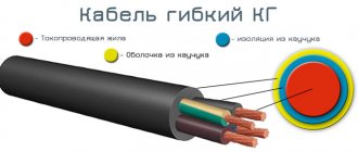
In many areas of energy supply, professional electricians and installers give preference to KG and KG-HL cables (a different climatic version of the first). The main features of these products that set them apart from competitors are increased flexibility and resistance to extreme low or high temperatures.
The KG cable is used everywhere, but in most cases it is used for switching electrical appliances of enormous power (for example, a welding machine).
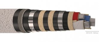
Cable design features
Let's consider all the components of the cable:
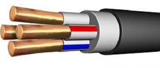
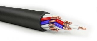
- A conductor consisting of numerous copper wires of round cross-section. In the process of manufacturing cores for CG cables, they are guided by GOST standards. For use in tropical climates, special “T” cores are produced: in addition to copper, tin is added to them. Alternatively, copper can be coated with a lead-tin layer, and the content of the first metal in the alloy must be at least 40%.
- All cores are hidden under a common film made of synthetic material. It acts as a separator.
- For insulation, special vulcanized rubber is used, and the coating is painted in a color that matches the purpose of the core. For example, blue is chosen for the neutral, yellow-green for the grounding circuit, etc. Instead of being completely painted, all the cores can be white with stripes of the desired color. In the absence of a neutral conductor, a blue stripe is applied to any other conductor with the exception of yellow-green. In addition to coloring, a symbolic designation can be used (for neutral - “0”). Wires with one or two cores usually do not have a strict coloring. The phase is often indicated by brown or black.
- All conductors are twisted together with a certain pitch. In the KG cable, the interval is 16 diameters, taking into account the insulating layer.
- After this, a second separation layer is placed. Again, a film of synthetic material is taken, with which the twisted conductors are covered. For example, this could be a microtalc product. In case of separation of cores from the sheath, the separating film is not used.
- The outer insulating layer is made of butadiene rubber. For wires with one core, instead of using different insulations for the core and the cable as a whole, a single protective sheath can be used. The thickness will be identical to two layers.
Explanation of marking KG 1*35
TO
- cable.
G
- flexible.
1
- number of copper stranded cores.
35
- cross-section of cores in square millimeters. The marking may also contain the following designations: (0.66) - rated voltage up to 660 Volts. (0.38) - rated voltage up to 380 Volts.
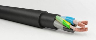
Cable design KG 1x35
1) Core - copper, multi-wire, round, fifth class according to GOST 22483. 2) Separating layer - synthetic film or talc layer. 2) Insulation – made of insulating rubber. 3) The shell is made of hose rubber.
Explanation of markings
Let's decipher the possible letter designations for the KG cable and its modifications:
- “K” – cable;
- “G” – flexible type;
- “N” – there is an additional protective layer that prevents combustion;
- “T” – can be successfully used in tropical climates with a minimum permissible air temperature of -10 degrees. Celsius;
- “HL” – intended for use in cold climates with a minimum permissible temperature of -60 degrees. Celsius.
Modifications
The KG cable is available in various modifications. Two of them, KGVV and RKGM, will be discussed below. The KGVV wire is characterized by the presence of polymer insulation (instead of rubber as in the standard one). It could be polyvinyl chloride. Thanks to this, the service life of the product increases significantly (25 years). Using KGVV, they switch bulky and high-power equipment, devices connected to AC and DC sources. Examples include excavators working in a quarry, cranes, etc.
The polyvinyl chloride insulating layer significantly expands the operating temperature range, which ranges from -50 to +50 degrees. Celsius. Thanks to this, the KGVV cable does not have climatic modifications, since it can be used under any conditions.
When connecting the KGVV to an AC electrical network, you need to monitor the maximum voltage and frequency - up to 660/1000 V and 60 Hz, respectively. When switching with DC networks, the voltage should be in the range of 1000-1500 V. The non-flammable properties of KGVV are manifested exclusively when installed alone. Group installation of a cable with other wires does not provide such protection.
Another modification of the CG is RKGM. This abbreviation stands for as follows:
- “R” – rubber insulation;
- “K” – layer of organosilicon;
- “G” – bare;
- “M” – copper conductors.
When examining the design of the RKGM, one can find strands of copper wires, an insulating layer of silicone rubber and a high-quality braid of glass fiber impregnated with varnish.
For other technical and operational parameters, we highlight the following:
- The cross-sectional area of the cores is in the range of 0.75-120 square meters. mm;
- bending radius – from two outer diameters;
- operating temperature range – from -60 to +180 degrees. Celsius;
- withstands operation in conditions of 100% humidity at a temperature of +35 degrees. Celsius;
- It is possible to connect to an alternating current source at a voltage of 660 V and a frequency of 40 Hz.
Often, electrical products are used to connect equipment and electrical appliances to AC and DC networks. It is possible to install the cable by air, which is due to increased resistance to precipitation, mechanical and wind loads, and ultraviolet rays of the sun.
The main requirement is related to the absence of contact area with a chemically aggressive environment, mineral or natural oils. Thus, before connecting the RKGM, make sure in advance that there are no oil stains indicating equipment leakage. If there are any, then you must first eliminate any leaks by cleaning the surface. Similar to other types of cables, RKGM is selected depending on the load.
Difference between cables KG, KG-HL and KGN
Regardless of the type of cable, it is suitable for all areas of operation listed in the first section of the article. Any CG is resistant to ultraviolet radiation, and is also used for switching mobile units.
Structurally, the cores of each wire consist of copper wires, have insulation and a separating layer of polyethylene terephthalate. Manufacturers choose natural or vulcanized rubber to insulate the cores, while the sheath is made of isoprene synthetic rubber.
There are several types of cable depending on the climatic version. Let's look at the main differences:
- KG is a standard wire with an operating temperature range from -40 to +50 degrees. Celsius;
- KG-HL – modification for cold climates (from -60 to +50 degrees Celsius);
- KG-T – for tropical climates (from -10 to +55 degrees Celsius);
- KGN is a product characterized by resistance to oils, having a fireproof shell (from -30 to +50 degrees Celsius) and intended for use in aggressive environments.
KG-T stands out from the rest in that the current-carrying copper conductors are additionally coated with tin or its alloy with lead (40/60 ratio). The insulation of such a wire, which can be used in tropical areas with a hot and humid climate, must meet special requirements. Fungicides are added to butadiene rubber to prevent the formation and spread of mold or mildew. These substances are not used in other modifications of CG.
The KG-HL cable is used in low temperature conditions (for example, in the Arctic and Antarctic). To create such a product, new technologies for protecting insulation and rubber were required. The latter must withstand extremely low temperatures. To do this, organosilicon substances are added to the composition of butadiene or natural rubber. Thanks to this approach, the minimum permissible temperature was increased to -60 degrees. Celsius.
KGN contains chloroprene rubber, which makes it possible to increase resistance to oil and make the rubber less flammable. Such products are successfully used in mines and quarries.
A regular KG can be easily replaced with other modifications - KG-HL and KGN. On the other hand, reverse replacement can lead to dire consequences. The situation is similar with wires intended for use in networks with voltages of 380 and 660 V. Direct replacement is acceptable, reverse replacement is not.
Main design parameters of the cable - KG
| Number and nominal cross-section of cable cores KG, mm² | Nominal outer diameter of cable KG, mm | Estimated cable weight KG kg/km |
| 1x2.5 | 6,7 | 80 |
| 1x4 | 8,0 | 110 |
| 1x6 | 9,0 | 150 |
| 1x10 | 11,1 | 230 |
| 1x16 | 12,4 | 310 |
| 1x25 | 14,6 | 450 |
| 1x35 | 16,4 | 590 |
| 1x50 | 19,0 | 820 |
| 1x70 | 21,5 | 1090 |
| 1x95 | 24,3 | 1400 |
| 1x120 | 27,7 | 1730 |
| 1x150 | 30,1 | 2070 |
| 1x185 | 32,7 | 2490 |
| 1x240 | 36,8 | 3190 |
| 1x300 | 40,1 | 3910 |
| 1x400 | 43,4 | 4980 |
| 2x0.75 | 8,2 | 90 |
| 2x1.0 | 8,5 | 100 |
| 2x1.5 | 9,4 | 130 |
| 2x2.5 | 11,2 | 190 |
| 2x4 | 13,5 | 280 |
| 2x6 | 15,5 | 380 |
| 2x10 | 21,1 | 680 |
| 2x16 | 23,7 | 920 |
| 2x25 | 28,4 | 1340 |
| 2x35 | 31,2 | 1680 |
| 2x50 | 38,0 | 2450 |
| 2x70 | 42,2 | 3170 |
| 2x95 | 47,4 | 4040 |
| 2x120 | 50,7 | 4800 |
| 2x150 | 57,5 | 6050 |
| 3x0.75 | 8,9 | 110 |
| 3x1.0 | 9,1 | 120 |
| 3x1.5 | 10,1 | 160 |
| 3x2.5 | 12,0 | 230 |
| 3x4 | 14,5 | 350 |
| 3x6 | 16,6 | 460 |
| 3x10 | 22,3 | 840 |
| 3x16 | 25,4 | 1130 |
| 3x25 | 30,4 | 1660 |
| 3x35 | 34,0 | 2150 |
| 3x50 | 39,5 | 2970 |
| 3x70 | 44,7 | 3930 |
| 3x95 | 50,9 | 5100 |
| 3x120 | 54,4 | 6150 |
| 3x150 | 63,0 | 7870 |
| 4x1.0 | 10,1 | 150 |
| 4x1.5 | 11,1 | 200 |
| 4x2.5 | 13,3 | 290 |
| 4x4 | 16,0 | 420 |
| 4x6 | 18,5 | 590 |
| 4x10 | 24,4 | 1000 |
| 4x16 | 27,8 | 1400 |
| 4x25 | 33,7 | 2100 |
| 4x35 | 37,7 | 2730 |
| 4x50 | 43,8 | 3700 |
| 4x70 | 49,7 | 5000 |
| 4x95 | 56,6 | 6500 |
| 4x120 | 62,0 | 8120 |
| 4x150 | 69,2 | 9880 |
| 5x1.0 | 11,1 | 190 |
| 5x1.5 | 12,2 | 240 |
| 5x2.5 | 14,6 | 350 |
| 5x4 | 17,8 | 530 |
| 5x6 | 20,2 | 720 |
| 5x10 | 26,8 | 1250 |
| 5x16 | 30,9 | 1700 |
| 5x25 | 37,4 | 2600 |
| 5x35 | 44,5 | 3440 |
| 5x50 | 50,1 | 4580 |
| 5x70 | 54,9 | 5920 |
| 5x95 | 63,3 | 7820 |
| 5x120 | 67,0 | 9360 |
| 2x0.75+1x0.75 | 8,9 | 110 |
| 2x1+1x1 | 9,1 | 100 |
| 2x1.5+1x1.5 | 10,1 | 160 |
| 2x2.5+1x1.5 | 11,8 | 220 |
| 2x4+1x2.5 | 13,9 | 310 |
| 2x6+1x4 | 16,3 | 440 |
| 2x10+1x6 | 21,0 | 740 |
| 2x16+1x6 | 25,0 | 1070 |
| 2x25+1x10 | 30,0 | 1550 |
| 2x35+1x10 | 32,4 | 1890 |
| 2x50+1x16 | 37,9 | 2600 |
| 2x70+1x25 | 42,7 | 3400 |
| 2x95+1x35 | 48,6 | 4500 |
| 2x120+1x35 | 54,4 | 5880 |
| 2x150+1x50 | 58,1 | 6590 |
| 3x2.5+1x1.5 | 13,2 | 280 |
| 3x4+1x2.5 | 15,5 | 400 |
| 3x6+1x4 | 18,0 | 560 |
| 3x10+1x6 | 23,5 | 950 |
| 3x16+1x6 | 27,6 | 1300 |
| 3x25+1x10 | 33,1 | 1950 |
| 3x35+1x10 | 36,5 | 2400 |
| 3x50+1x16 | 42,4 | 3400 |
| 3x70+1x25 | 47,7 | 4500 |
| 3x95+1x35 | 54,5 | 5890 |
| 3x120+1x35 | 60,9 | 7280 |
| 3x150+1x50 | 64,9 | 8630 |
Color designation of cores of power cable KG
The outer insulating layer of a single core is painted in the desired color or has a blue stripe along its entire length. Most often, the grounding circuit is made yellow-green, the neutral conductor is blue or cyan (or with the symbol “0”).
When designating the cores of a KG cable, it is prohibited to use three colors - red, white and gray. Other shades are acceptable, but the designation is not important. Depending on the individual preferences of the customer, the cores can be painted in certain colors, have stripes, or be produced without colors.
Depending on the number of cores, the colors may be as follows:
- three veins - yellow-green, blue and brown;
- four – yellow-green, blue, black and brown;
- five – yellow-green, blue, brown and two black;
- six – yellow-green, blue, brown and three black.
Technical characteristics of the KG cable
There are several configurations of the CG cable depending on climatic and weather conditions:
- U – temperate zone;
- HL – cold-resistant;
- T – tropics and subtropics.
Dimensions
Any electrical cables can be divided into several categories depending on the number of cores. Another dimensional indicator on which the power of connected devices depends is the cross-sectional area of the conductor:
- for a single-core wire, the cross-section is in the range of 2.5-50;
- two or three – 1-150;
- four – 1-95;
- five – 1-25 sq. mm
The grounding conductor is usually made with a smaller cross-section compared to the phase conductor. This must be indicated in the product abbreviation. For example, KG 2×5+1×3 can be deciphered as follows: flexible cable with two phase conductors of 5 kW each. mm and one grounding 4 sq. mm.
Important! For wire with conductors 1-1.5 sq. mm, the cross-sectional area of the grounding conductor is identical to the phase conductor.
Manufacturers produce cable in coils. The length depends on the cross-sectional area. The following dependence is observed:
- for wire 1-35 sq. mm – 150 m;
- 35-120 sq. mm – 125 m;
- 150 sq. mm – 100 m.
Thus, the larger the cross-section, the shorter the cable.
Temperature indicators
The standard KG cable can be used at temperatures from -40 to +50 degrees. Celsius. The service life of the product depends on compliance with this parameter. However, as stated above, there are several additional modifications with different temperature ranges.
Technical characteristics of the KG-HL cable
In addition to the extended operating temperature range, the KG-HL cable, in comparison with the standard KG, shows changes in other technical and operational parameters:
- For 1 km of cable, the insulation resistance must be at least 50,000 kOhm. The data is valid for air temperature +20 degrees. Celsius.
- KG-HL is capable of withstanding a load voltage of 2500 V for five minutes (at a frequency of 50 Hz).
- The number of cable bends without defects is 30,000.
- Operating temperature – from -60 to +50 degrees. Celsius.
- Different manufacturers set their own warranty periods - usually at least six months from the date of commissioning.
The diameter and weight of the cable are important parameters, especially considering that the product is used only for mobile mechanisms and installations.
KG-HL
View prices →
Description
The KG-HL cable is a power cable with stranded copper cores and rubber insulation. The sheath made of cold-resistant rubber allows the KG-HL cable to be used at temperatures down to -60 C. It is resistant to solar radiation. The cable is intended for the transmission and distribution of electrical energy in installations with a rated alternating voltage of 380 V, frequency up to 400 Hz, or a constant rated voltage of 660 V.
KG-HL cable design:
- Current-carrying conductor twisted from copper wires (class 5);
- A layer of PET-E polyethylene terephthalate film;
- Rubber insulation type RTI-1-HL based on natural and butadiene rubbers.
- — digital marking: 1, 2, 3, 4, 5, grounding conductor — 0,
- — color marking: blue, black, brown, grounding conductor — green-yellow;
- A layer of PET-E polyethylene terephthalate film (on top of twisted insulated cores);
- Sheath made of rubber type RSHTM-2-KhL based on isoprene and butadiene rubbers; insulating and protective sheath of single-core cables made of rubber type RTISH-KhL based on isoprene and butadiene rubbers.
Explanation of KG-HL:
K - cable G - flexible HL - climatic version - cold-resistant (from -60 C to +50 C)
Characteristics
Conditions for laying and operating the KG-HL cable:
The cable is intended for use on land, rivers and lakes in macroclimatic areas with moderate and cold climates, outdoors and indoors.
Repeated bending of the cable through the roller system:
| Roller diameter | Tensile load | Section of main cores | Number of bending cycles |
| 120 mm | 15 N | 2.5 sq.mm | 30 000 |
| 200 mm | 20 N | 4.0 sq.mm | 30 000 |
Multiple cable bends at an angle ±P/2 rad with a tensile force of 49 N:
| Roller diameter | Section of main cores | Number of bending cycles |
| 200 mm | from 6.0 to 16 sq. mm | 90 000 |
| 200 mm | from 25 to 50 sq.mm | 60 000 |
| 400* mm | from 70 to 120 sq.mm | 40 000 |
* for single-core cables, the roller diameter should be no more than 200 mm.
Technical characteristics of the KG-HL cable:
| Warranty period | 6 months |
| Long-term permissible temperature on the core, no more | 75°C |
| Test alternating voltage with a frequency of 50 Hz, 5 min. | 2.5kV |
| Maximum operating temperature of the core | 75°C |
| Rated alternating voltage frequency 400 Hz | 0.66 kV |
| Rated DC Voltage | 1 kV |
| Cable bending radius | 8 bunk diameters |
| Tensile force of cables per 1 sq. mm. total cross-section of all cores, no more | 19.6 N |
| Construction length, not less | 150 m |
| Ambient temperature, upper limit | 50°C |
| Ambient temperature, lower limit | -60°C |
| Electrical insulation resistance of main cores at 20°C, not less | 50 MOhm x km |
Group characteristics
Flexible power cables
This group includes cables with copper stranded conductors with rubber insulation in a rubber sheath, intended for power supply to mobile consumers and for non-stationary installation.
Brands and scope
| Cable brand | GOST, TU | Application area |
| KG kg-hl kg-t kg kgn kpg kpgs kpgsn | TU 16.K73.05-93 | For connecting mobile mechanisms to electrical networks for rated alternating voltage up to 660 V with a frequency of up to 400 Hz or direct voltage up to 1000 V |
| KOG-1 | TU 16.K73.03-88 | For connection during arc welding of electric holders of welding installations with a rated voltage of 220 V AC with a frequency of 50 Hz or DC |
| KGE | TU 16.K73.02-89 | For connecting excavators and other mobile machinery to electrical networks with a rated voltage of 6 kV AC with a frequency of 50 Hz. |
| KShVGT-10 | TU 16-705.101-79 | For stationary and mobile installation and connection of mobile mechanisms to electrical networks with a rated voltage of 10 kV AC with a frequency of 50 Hz |
Designs and operating conditions
| Cable brand | Design | terms of Use |
| KG | Basic (with copper stranded conductors with rubber insulation in a rubber sheath) | For bends with a radius of at least 8 cable diameters, at ambient temperatures from -40 to +50°C when exposed to solar radiation |
| KG-HL | Using cold climate tires | The same, at ambient temperatures from -60 to +50°C |
| KG-T | With tinned copper wires and rubber for tropical climates | The same, at ambient temperatures from -10 to +55°C, with resistance to mold fungi |
| KGN | In an oil-resistant, flame-retardant shell | When bending with a radius of at least 8 cable diameters, with the possibility of oil getting on the sheath, at an ambient temperature from -30 to +50°C |
| CNG | With highly flexible cores | For bends with a radius of at least 5 cable diameters, at ambient temperatures from -50 to +50°C when exposed to solar radiation |
| CPGS | With highly flexible cores and profiled core | The same, if the cable can be exposed to shock and crushing loads |
Number of cores in cables
| Cable brand | Number of cores | Nominal cross section | ||
| main | grounding | auxiliary | main cores, mm2 | |
| KG, KG-T and kg-hl, kg | 1 | — | — | 2,5 — 120 |
| 2iЗ | — | — | 0,75 — 120 | |
| 2&3 | 1 | — | 0,75 — 120 | |
| 2&3 | — | 1 | 2,5 — 70 | |
| 2&3 | — | 2 | 2,5 — 70 | |
| 4&5 | — | — | 1,0-25 | |
| CNG | 2 | — | — | 0,75 — 70 |
| 2&3 | 1 | — | 0,75 — 70 | |
| KPGSi kgpsn | 3 | 1 | — | 2,5 — 120 |
| 3 | 1 | 1 | 2,5 — 6,0 | |
| 3 | 1 | 2 | 4,0 — 50 | |
| KOG-1 | 1 | — | — | 16- 150 |
| KGE | 3 | 1 | — | 10- 150 |
| 3 | 1 | 1 | 10- 150 | |
| KShVGT-10 | 3 | 3 | — | 25 — 150 |
Core cross-section, mm2
| Main veins | Grounding conductors | Grounding conductors for KShVGT-10 | Auxiliary cores |
| 0,75 | 0,75 | — | — |
| 1,0 | 1,0 | — | — |
| 1,5 | 1,0 | — | 1,5 |
| 2,5 | 1,5 | — | 1,5 |
| 4,0 | 2,5 | — | 2,5 |
| 6,0 | 4,0 | — | 4,0 |
| 10 | 6,0 | — | 6,0 |
| 16 | 6,0 | — | 6,0 |
| 25 | 10 | 6,0 | 10; b.O for KGE |
| 35 | 10 | 6,0 | 10; b.O for KGE |
| 50 | 16 | 10 | 10 |
| 70 | 25, 16 for KGE | 10 | 10 |
| 95 | 35, 25 for KGE | 16 | 10 for KGE |
| 120 | 35 | 16 | 10 for KGE |
| 150 | 50 | 25 | 10 for KGE |
The nominal insulation thickness and sheath thickness values for cables of the KG, KG-HL, KG-T, KGN, KPG, KPGS, KPGSN brands are indicated in Table 4.2.3-3 (higher sheath thickness values apply to cables with a large number of cores) . Cable cores of brands KG, KG-HL, KG-T, KGN, KPG, KPGS, KPGSN must have digital markings or distinctive colors indicated in Table 4.2.3-4, while green-yellow insulation color is used only for the grounding core. The nominal thicknesses of insulation and sheaths for cables of the KOG-1 brand are given in Table 4.2.3-5, the nominal thicknesses of structural elements for cables of the KGE brand are given in Table 4.2.3-6, the nominal thicknesses of structural elements for cables of the KShVGT-10 brand are given in the table 4.2.3-7. The color of insulation for cables of the KOG-1 and KGE brands is not standardized; in cables of the KShVGT-10 brand, the main cores can have any color except black.
Insulated conductors must be twisted in the right direction, and to ensure operation under given conditions, insulated conductors in cables of the KG, KGN brands with three main and two auxiliary conductors with a cross-section of 16 mm2 or more, cables of the CPG brand with four conductors of 16 mm2 or more must be twisted around the rubber core, and in cables of the KPSG and KPSGN brands with four cores with a cross-section of 16 mm2 or more, five- and six-core all sections must be twisted around a round or profiled rubber core. In cables of the KShVGT-10 brand, all insulated cores must be twisted with a core made of electrically conductive rubber in the center, and the shell is made of two layers with an inner layer of electrically conductive rubber.
To make cable cutting easier, a layer of synthetic film or other material should be placed over the twisted cores. In cables of the KOG-1 brand and single-core cables of the KG brand, it is allowed to replace the insulation and sheath with an insulating protective sheath. The nominal thickness of the sheath must be equal to the sum of the thicknesses of the insulation and sheath.
Reference values for the outer diameters and masses of cables of the most widely produced standard sizes are indicated in Tables 4.2.3-8 and 4.2.3-9, respectively. Taking into account significant tolerances, actual values may differ by 10% down or up.
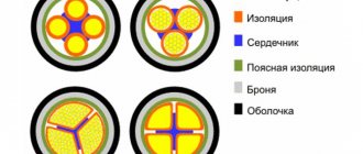
Cross section of KGE brand cable
1. Grounding conductor; 2. Main core with an electrically conductive element; 3. Insulation; 4. Electrically conductive insulation screen; 5. Belt screen made of electrically conductive rubber; 6. Auxiliary insulated core; 7. Shell.
Insulation and sheath thicknesses for cables of brands KG, KG-HL, KG-T, KGN, KPG, KPGS, KPGSN, mm
| Nominal cross-section of main cores, mm2 | Insulation | Sheath for single-core cables | Sheath for multi-core cables |
| 0,75 | 0,8 | — | 1,3- 1,5 |
| 1,0 | 0,8 | — | 1,3- 1,6 |
| 1,5 | 0,8 | — | 1,5- 1,8 |
| 2,5 | 0,9 | 1,4 | 1,7-2,0 |
| 4,0 | 1,0 | 1,5 | 1,8-2,2 |
| 6,0 | 1,0 | 1,6 | 2,0 — 2,5 |
| 10 | 1,2 | 1,8 | 3,1 -3,6 |
| 16 | 1,2 | 1.9 | 3,3 — 3,9 |
| 25 | 1,4 | 2,0 | 3,6 — 4,4 |
| 35 | 1.4 | 2,2 | 3,6 — 4,5 |
| 50 | 1,6 | 2,4 | 4,5 — 5,0 |
| 70 | 1,6 | 2,6 | 4,8 — 5,0 |
| 95 | 1,8 | 2,8 | 5,0-5,3 |
| 120 | 1,8 | 3,0 | 5,0 — 5,3 |
Colors of cores for cables of brands KG, KG-HL, KG-T, KGN, KPG, KPGS, KPGSN
| Number of cores | Color without grounding conductor | Coloring with grounding conductor |
| 3 | blue, black, brown | green-yellow, blue, brown |
| 4 | blue, black, brown, black or brown | green-yellow, blue, black, brown |
| 5 | blue, black, brown, black or brown, black or brown | green-yellow, blue, black, brown, black or brown |
| 6 | — | green-yellow, black, blue, black, brown, black |
Insulation and sheath thicknesses for KOG-1 cables, mm
| Nominal cross-section of main cores, mm2 | Internal and external screens for core and insulation | Insulation | Belt screen | Shell |
| 10-50 | 0,4 | 4,0 | 1,5 | 3,5 |
| 70-150 | 0,6 | 4,0 | 2,0 | 4,0 |
Thicknesses of structural elements for cables of the KShVGT-10 brand, mm
| Nominal cross-section of main conductors, mm2 | Internal screen along the core | Insulation | External insulation screen | Inner shell | Outer shell |
| 25-70 | 0,8 | 6,0 | 1,0 | 3,0 | 5,0 |
| 95-150 | 1,2 | 6,0 | 1,0 | 3,0 | 6,0 |
Electrical Requirements
For the period of acceptance and delivery, cables of the KG, KG-HL, KG-T, KGN, KPG, KPGS, KPGSN brands must withstand an alternating voltage test for 5 minutes without immersion in water, and single-core cables and cables of the KOG-1 brand after being in water 2.5 kV with a frequency of 50 Hz. Cables of the KGE brand must withstand a voltage test of 15 kV, and cables of the KShVGT-10 brand - 20 kV alternating current with a frequency of 50 Hz for 5 minutes.
The electrical insulation resistance under normal climatic conditions, recalculated per 1 km of cable, upon acceptance and delivery must be at least 50 MΩ, for cables of the KShVGT-10 brand, at least 100 MΩ.
Outer diameters of cables, mm
| Nominal cross-section of main cores, mm2 | Single-core brands KG, KG-HL, KG-T | With three main conductors and a grounding conductor of brands KG, KG-HL, KG-T, KGN | With three main conductors and a grounding conductor of the CNG brand | With three main conductors and a grounding conductor of brands KPGS, KPGSN | KOG-1 | KGE | KSHVGT - 10 |
| 0,75 | — | 10 | 10 | — | — | — | — |
| 1,0 | — | 10 | 10 | — | — | — | — |
| 1,5 | — | 11 | 11 | — | — | — | — |
| 2,5 | 7,0 | 13 | 13 | 16 | — | — | — |
| 4,0 | 8,0 | 16 | 16 | 18 | — | — | — |
| 6,0 | 9,0 | 18 | 19 | 22 | — | — | — |
| 10 | 10 | 23 | 24 | 25 | — | 41 | — |
| 16 | 13 | 25 | 28 | 30 | 10 | 44 | — |
| 25 | 15 | 30 | 32 | 34 | 12 | 46 | 67 |
| 35 | 17 | 35 | 38 | 38 | 14 | 50 | 72 |
| 50 | 19 | 42 | 44 | 45 | 16 | 54 | 74 |
| 70 | 22 | 45 | 49 | 49 | 18 | 63 | 79 |
| 95 | 24 | 51 | — | 53 | 20 | 67 | 86 |
| 120 | 27 | 56 | — | 58 | 23 | 72 | 91 |
| 150 | — | — | — | — | 25 | 78 | 97 |
Cable weights, kg/km
| Nominal cross-section of main cores, mm2 | Single-core brands KG, KG-HL, KG-T | With three main conductors and a grounding conductor of brands KG, KG-HL, KG-T, KGN | With three main conductors and a grounding conductor of the CNG brand | With three main conductors and a grounding conductor of brands KPGS, KPGSN | KOG-1 | KGE | KSHVGT - 10 |
| 0,75 | 140 | 140 | — | — | |||
| 1,0 | — | 150 | 150 | — | — | — | — |
| 1,5 | — | 190 | 190 | — | — | — | — |
| 2,5 | 70 | 280 | 280 | 310 | — | — | — |
| 4,0 | 100 | 390 | 400 | 430 | — | — | — |
| 6,0 | 130 | 540 | 570 | 600 | — | — | — |
| 10 | 210 | 910 | 990 | 1100 | — | 2000 | — |
| 16 | 290 | 1200 | 1300 | 1400 | 240 | 2300 | — |
| 25 | 420 | 1700 | 1900 | 2000 | 320 | 2900 | 4900 |
| 35 | 560 | 2300 | 2600 | 2600 | 440 | 3500 | 5800 |
| 50 | 760 | 3100 | 3600 | 3700 | 610 | 4100 | 6700 |
| 70 | 1000 | 4100 | 4800 | 4800 | 840 | 5600 | 7900 |
| 95 | 1300 | 5300 | — | 5500 | 1100 | 6900 | 9700 |
| 120 | 1600 | 6300 | — | 6500 | 1400 | 8100 | 11000 |
| 150 | — | — | — | — | 1700 | 9600 | 13000 |
← Back
Options for laying the KG cable
An electrical product can be laid in different ways. Let's list the main ones:
- In pipes, when additional protection from external negative factors and mechanical loads is required when installed in an open area. For these purposes, you can use ceramic, metal and polyvinyl chloride pipes. The installation process is carried out in accordance with the points of the PUE (rules for installation), therefore, at the points of contact of different parts, it is necessary to ensure a tight connection and the absence of gaps. This will prevent any molecules from getting inside the pipe. To get rid of gaps, use special couplings. Install heat-resistant protection (for example, resin tape) at the inlet and outlet. The diameter of the pipe should be two to three times larger than the cable.
- In gutters - a more popular and widespread method, which is actively used when laying products in a chemically aggressive environment (workshops, production facilities). The cross-sectional area of cables placed in gutters should not exceed 16 square meters. mm. The main feature of the installation is that all the wires are placed in one layer at a certain distance. Thus, the width of the gutter is selected depending on the number of wires, and taking into account the interval between each of them.
- Air laying. When choosing this method, you must first take into account all environmental factors that may affect the cable. Do not forget that wind and precipitation can place additional load on both the cable and the supporting structure (overpass, cable). Severe operating conditions may result in connection failure or loss.
- Open gasket. The simplest method, according to which there is no need to use additional materials and structures. Can be used provided there is no threat of breakage or loads. Relevant for facilities with a small number of people and the ability to place the suspension at a sufficient height. It is strictly forbidden to place cables in passages. A very economical method, the implementation of which does not require machinery or special equipment. However, unexpected hazards may arise during the installation process. Requires responsibility and care.
- Laying the KG cable in the ground is unrealistic and undesirable, therefore its protection does not imply such operation. This can lead to damage and breakage due to construction waste, increased soil density, etc.
- On ships they use a modification of the KG-HL cable.
Thus, the standard CG and its modifications make it possible to ensure reliable switching of mobile installations and units. It is important to remember that the electrical product is only suitable for temporary connection, so you should not hide it far. The main disadvantage is the lack of possibility of laying underground. Compared to numerous analogues, the KG cable will be more expensive, but its high cost is compensated by its unsurpassed technical and operational characteristics.