In recent years, non-burning methods for searching for damage to energy cables have become quite widespread in Russia. The possibilities for using such methods in the Russian power grid remain limited. This is due to the fact that most of the cable lines remain unrouted, and on such cables, no-burning methods and acoustic search alone will not do. Therefore, the most popular scheme for searching for faults on energy cables in Russia remains and will remain in the coming years the following scheme:
The key to effective work under this scheme is high-quality burning installations from the ANGSTREM company. To find faults using pulse reflectometry and induction search, burning is required to ensure the transformation of high-resistance single-phase cable faults into low-resistance two or three-phase cables with the appearance of a reliable metal bridge at the damage site. If during burning it is possible to achieve a short circuit between the core and the core, then problems with finding the exact location of the damage no longer arise. On the other hand, “pumping” high power into the cable during the burning process should not lead to the cable failing in other places.
Burning a high-voltage cable is a preparatory procedure that ensures the possibility of using a set of weapons of mass destruction methods. Some OMP methods are applicable only when the transient resistance at the site of insulation damage is no more than hundreds or even units of Ohms (in some cases, tenths of an Ohm). Reducing the contact resistance is the task of burning.
Burning process technology:
First stage
— preliminary high-voltage burning of the cable, carried out using high voltage and low currents until a breakdown occurs in the cable. A standard burning installation produces a maximum voltage of about 20–25 kV. The high-voltage burning process occurs as follows: a minimum voltage is applied to the damaged cable and then it gradually rises to 20–25 kV or to the value at which breakdown can be achieved, after which the burning process begins.
The maximum voltage when burning a cable should not exceed 0.5–0.7 U isp., however, in practice, such voltage is not always enough to carry out preliminary burning. If a burning installation that produces a maximum voltage of 20–25 kV is not able to provide cable breakdown, an additional installation with a maximum voltage of 60–70 kV, but with less power, is used in combination with it. Equipment of this type is called installations for testing and burning high-voltage cables; they can be connected to the burning installation or used separately.
Second phase
- burning of the cable begins from the moment of breakdown and the occurrence of a short circuit and is carried out by lowering the voltage and increasing the current until the single-phase circuit is converted into two or three-phase (welding core to core). Initially, the high voltage source destroys the cable insulation with a minimum current, then, as the burn is carried out, the voltage values gradually decrease and the current values increase.
In the case of additional use of a testing and burning installation with a maximum voltage of 60–70 kV, it carries out the burning process with a voltage from 60–70 kV to 20–25 kV, after which the main burning installation, which has a higher power, is automatically switched on.
Third stage
— afterburning of the cable is the final stage of burning and is carried out at low voltages and high currents of the order of 20–60 A, depending on the model of the burning installation. This stage is carried out using a low-voltage source, which is automatically connected when the voltage drops to certain values.
In the event of a short circuit of one core to the shell, to destroy the conductive bridge between the core and the shell, special sufficiently powerful burning installations are used, capable of delivering high current values (300 A). It should be noted that the use of installations of this type can lead to a decrease in the life of the cable and its damage in other, “weak” places.
Execution order
Typically, in practice, either a short circuit or a break in the cable cores occurs. The first fault can be high or low resistance. Carrying out a callback shows the presence of a short circuit in the latter case, but for the first option a burning procedure will also be required. This is the only way to penetrate the insulating layer and transform the short circuit into a low-resistance one or transfer a single-phase fault to a 2-3 phase one.
At the first stage, the procedure is performed at low current levels and a sufficiently high voltage. An insulation breakdown and a methodical decrease in voltage are observed in parallel with a decrease in resistance in the defect area. But the current flow rates begin to increase. The resistance decreases by an order of magnitude from kOhm to several ohms. The piercing power is limited by changing the voltage. The process algorithm in various modifications has a wide range and can be used for both alternating and direct current.
Types of cable burning units supplied
| Name of equipment | Testing and burning installations (60-70 kV) | Burning installations (voltage 20 - 25 kV, current from 20 A) | Afterburning installations for destroying the bridge between the core and the sheath (current 300 A) |
| AIP-70 | ✓ | ||
| VPU-60 (replaces AID-60P “Vulcan”) | ✓ | ||
| APU-1-3M | ✓ | ||
| APU-2M | ✓ | ||
| MPU-3 "Phoenix" | ✓ | ||
| UD-300 | ✓ | ||
| UD-300M | ✓ | ||
| AIP-70 + APU-1-3M | ✓ | ✓ | |
| AIP-70 + APU-2M | ✓ | ✓ | |
| IPK-1, VPU-60 + MPU-3 “Phoenix” | ✓ | ✓ |
The ANGSTREM company supplies three types of burning installations:
- Installations for testing and burning high-voltage cables with a maximum voltage of 60–70 kV, used as auxiliary equipment in the initial stages of burning.
- Burning installations with a maximum voltage of 20–25 kV, with several high-voltage and one low-voltage sources.
- Afterburning installations designed to destroy the metal bridge between the core and the sheath with high currents (300 A) in the event of a single-phase short circuit to the core.
When choosing a particular model, it is necessary to take into account both production tasks and the characteristics of existing equipment and its compatibility with the purchased one.
An example of compatibility of ANGSTREM equipment for burning
Device for welding two cores in a faulty cable
I present to the readers the first article of the summer competition. I remind you that all articles of the previous competition, as well as the rules and results, can be seen at this link.
Author – Marchenko Boris Danilovich.
Here's what he says about himself:
I am an electrical engineer, retired. From time to time, active power engineers and heads of local enterprises approach me with various requests. I have several publications in specialized journals.
Below is the article:
Main technical characteristics of burning installations
| Name of equipment | Maximum output voltage, kV | Maximum output current, A | Number of steps | Characteristics of stages, kV |
| APU 1-3M | 24 | 40 | 4 | 25; 5; 1; 0,3 |
| APU-2M | 30 | 80 | 8 | 30; 17; 8; 5; 1,7; 1; 0,3; 0,18 |
| MPU-3 "Phoenix" | 20 | 20 | 4 | 20; 5; 0,6; 0,3 |
| UD-300 | 0,25 | 300 | 1 | 0,25 |
| IPK - 1 (VPU - 60 + MPU - 3 Phoenix) | 60 | 20 | 5 | 60; 20; 5; 0,6; 0,3 |
Device for welding two cores in a faulty cable
I present to the readers the first article of the summer competition. I remind you that all articles of the previous competition, as well as the rules and results, can be seen at this link.
Author – Marchenko Boris Danilovich.
Here's what he says about himself:
I am an electrical engineer, retired. From time to time, active power engineers and heads of local enterprises approach me with various requests. I have several publications in specialized journals.
Below is the article:
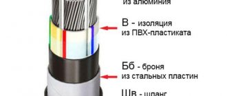
If the rules of technical operation of electrical cables are not followed, especially with paper insulation of type AAB-1 3*35, AAB 3*120, during prolonged operation, a “breakdown” (short circuit) is observed along the path of core - core or core - grounding shell.
The operation service learns that a “breakdown” has occurred after the automatic protection of the cable breaker is triggered. The consumer is left without electricity. You need to find the location of the “breakdown” in the cable and eliminate the fault.
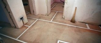
The actual use of the device in practice was repeatedly successfully used by me on underground cables at a depth of up to one meter. In all cases, welding of the cores was successful. To control the fact of welding, a conventional incandescent lamp is used, and the localization of the welding site (i.e., the breakdown site) with an accuracy of 0.5-1.0 meters along the cable profile is determined by a tape measure according to the readings of the P5 device.
The point where the cable “breaks down” is the core - the core has an insulation resistance in the range of 500...100 kOhm. To more accurately determine the location of the damage, devices such as R5-10, R5-13, etc., a sound generator and a cable finder are used. But for normal operation of search devices, it is necessary to reduce the cable insulation resistance to 10...2 ohms. To reduce the resistance, it is necessary to “burn out” the cable. For this purpose, devices such as UP-7, “phoenix”, etc. are used, which may or may not be available.
I offer my simple diagram of a device for welding cable cores. Due to the fact that the voltage in the 220 V cable causes a “breakdown” and the protection is triggered, this can be used for welding the core with the protective core of the cable. You only need to limit the current, turn on a resistance and a time relay in series to limit the welding time.
Fig.1. Diagram of a device for welding cores in a faulty cable.
The device circuit (see Fig. 1) consists of a small number of accessible parts. These are: a PME-211 starter with a 220 V coil, an A1 circuit breaker with an operating current of 150 ... 200 A, two powerful resistances R1 = 1.8 ohms and R2 = 1.8 ohms with a power of P = 500 W, which can be turned on if necessary sequentially. Time relay 4...10 sec. powered by a 220/24 transformer, 24 volts DC.
Other parts are an input circuit breaker with an operating current of 150-200 A, a current transformer 200/5, an ammeter 5A, a current relay with an operating current of 20A.
To control welding, a 220 V 75 watt lamp is installed. After turning off the PME-211 starter, if the lamp is on, it means that two cable cores have been welded.
When connecting, be sure to follow the correct connection sequence. One damaged cable core is grounded first. Then Re is connected to terminal X3 of the device. Connect N (zero) to terminal X2. Circuit breaker A1 is turned off and does not supply phase L1 to terminal X1. The device is ready for use.
To work, do the following. Turn on the machine A1, press the “Start” button and wait for welding.
Several attempts have been made to weld a power cable core to a grounded cable sheath. A positive result was not always obtained.
When burning, you need to remember fire and electrical safety.
The device is assembled in an old computer case. Weight 15 kg.
Photo of a device for welding cores in an electric cable
Now that the location of the breakdown is clearly marked, you can easily find this place and replace the damaged section of the cable.
Photo of the author with his invention:
Author Marchenko Boris Danilovich
Voting for the contest articles will begin on June 1, but in the meantime, ask questions to the author.
Important parameters of burning installations
The burning installation consists of several high-voltage sources and one low-voltage one. The maximum current and voltage values of each source are called stages, their number can vary from four to six. During the cable burning process, as the breakdown voltage decreases, the transition to the next burning stage is carried out. As soon as the installation parameters make it possible to switch on a more powerful stage for parallel operation (or separately), it is put into operation. A more powerful stage means a unit with lower internal resistance and higher current.
Main indicators
All of the above indicates that the main characteristics of the device will be the operating current and output voltage. The number of steps is also equally important.
The desired result can be achieved under this condition - the indicators of transient and internal voltage in the damage zone should correspond to each other as closely as possible. In reality, if these parameters differ significantly, the operation of the device is simply impossible.
Only the use of a multi-stage technique will help solve such a problem. The essence of the process is to switch at a lower transient voltage to a source with lower voltage parameters. Stages 3-6 have modern models of burning devices.
Several models of similar equipment:
Possibility of continuous burning
Old-style burning installations used manual switching of stages by the operator, which often led to interruption of the arc, increased the burning time and created the possibility of “swimming” breakdowns. Modern burning devices are equipped with automatic systems for switching burning stages, eliminating arc rupture at the burning site, which significantly reduces the time spent on preparatory work to find damage sites. Often such burning is called “stepless”, which should not mislead specialists: this concept does not mean the absence of several power units (stages) - simply switching between them is carried out automatically, without operator participation. To generate high voltage, the design of burning installations uses either oil transformers or “dry” transformers. The issue of automatic switching of stages without arc rupture has been resolved in both types of devices, however, there is an opinion that only dry transformers can provide continuous burning in any conditions. This phenomenon is associated with different energy consumption of two types of transformers in short circuit mode. Oil transformers have significantly higher power consumption in short circuit mode, so keeping them turned on simultaneously during the entire burning process is ineffective; therefore, when the voltage drops, the source with the oil transformer, which generates a higher voltage, is turned off. Very often, switching to a more powerful burning stage first leads to “swimming,” i.e. to increase the breakdown voltage, in this case you should return to the previous stage of a higher voltage, and then, after reducing the breakdown voltage, move on to the next stage.