Optical cable repair and features of its implementation
Current telecommunications are based on fiber optic communications.
This type of cable network is used to organize systems of any level (both local and intercontinental lines). Specialists use high technology when organizing linear connection elements, but it is not possible to completely eliminate the risk of damage to the cable during operation. Sometimes accidents occur even on structures with a high level of mechanical strength and round wire armor. If damage is observed, operators use the following methods to restore the communication line:
- 1. Switching to a backup direction - ensuring the fastest possible restoration of system functionality.
- 2. Reconstruction of the fiber optic cable - the complex is undergoing a comprehensive restoration in order to restore the stable functioning of the network.
Causes of defects in fiber optic cables
Defects in the optical cable network system appear due to the development of such situations:
- 1. Direct mechanical impact (mainly all kinds of construction equipment).
- 2. Move the support clamp at the insertion point.
- 3. In the event of a direct lightning strike (such risks increase significantly when the cable is equipped with metal armor, as well as when laying communications on rocky soil or in permafrost conditions).
The first situation involves a high level of effort and sudden impact. Therefore, a wire break may occur. In other situations, a partial violation of the integrity of the system may be observed. Therefore, it takes quite a long time to ensure high-quality communications.
Nuances in the field of repairing fiber optic cables
Reconstruction of an optical cable network, first of all, begins with performing an integrity check, as well as localizing the damaged area. At this stage, specialists use optical reflectometry. The device displays a backscatter curve, which allows you to correctly determine the distance to the location of the defect, as well as the nature of the damage that has occurred.
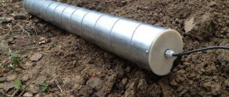
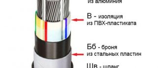
When forming a fiber optic line, it is prohibited to lay the cable with a reserve length (the exception is the technological reserve that allows connecting the wiring). Consequently, cable reconstruction almost always involves the installation of an insert. The junction of the cable pieces is reliably protected using a coupling. This device opens up possibilities in the placement of fiber splices, while ensuring the restoration of the protective function of the shell. If the technological nuances are observed, a guarantee of tensile strength of up to 75% of the values indicated in the cable specification appears.
Features of fiber optic cable repair
Before you begin restoring this type of cable, you need to check its integrity and the location of the point of damage. This procedure is accompanied by the use of optical reflectometry. An experienced specialist can not only determine the exact distance to the point of damage, but also its features.
When laying a fiber optic communication line, it is prohibited to leave additional length. That is why most often this type of restoration occurs through the installation of a regular insert. Figure 3 shows the use of the insert; the peculiarity is that this place must be additionally protected by a coupling. Thanks to a high-quality coupling, it will be possible not only to place all the joints there, but also to restore all the protective coatings.
Quality control of repair operations
The restoration of the optical cable system at the final stage involves the implementation of testing. This measure is carried out by taking measurements with a reflectometer on both sides of the restored line. The purpose of the task is to establish the quality of the reconstruction, namely, to establish compliance with the attenuation standards of the working wavelength (1310 and 1550 nm) in splices. Additionally, using an optical tester, specialists diagnose attenuation between the connectors of the system’s hardware components. The results of the measurements performed are recorded in the appropriate protocol, which is sent to the archive of line operational reports.
Troubleshooting fiber optics
Low-end devices are designed to monitor line continuity, while mid-price devices allow you to determine the level of optical power in the line. Serious diagnostics should be carried out using optical time domain reflectometers (OTDR). This is quite expensive equipment. If the power level is unsatisfactory or the OTDR detects a pinpoint problem, the first thing to do is clean and inspect the ends of the optical connectors.
SAFETY
Always take precautions when working with optics. The wavelengths used in optical networks are in the invisible range. The human eye perceives radiation of a certain spectrum: from violet (wavelength about 380 nm) to red (about 750 nm) (see Figure 1). Many optical networking sources are equipped with lasers, some of which are very powerful. Never look at the cross-section of an optical fiber or the end of a plug of optical equipment. If an optical connector is not in use, it should be covered with a special cap - this will protect your eyes from damage and at the same time protect the connector from contamination.
If you need to visually identify a port, the safest way is to point the end of the optical cable at a piece of white paper or hold the paper near the optical connection. Never look directly into the connection - there is always a risk that invisible radiation is emanating from it.
CONTINUITY TESTING
The continuity of the optical line and the polarity of paired optical fibers can be checked using special flashlights that emit a beam of white (or some other) color. Recently, very bright LED devices the size of a keychain have become especially popular. Flashlights specifically designed for use in computer networks are equipped with different types of adapters: SC, ST and others. The beam of light is generally better focused than in conventional flashlights (see Figure 2), and the color most often used is red, which is quite bright. However, they do not use incandescent lamps or lasers.
Another way to check continuity is to use a special visible light source to visually locate faults (Visual Fault Locator (VFL). It is equipped with a laser that operates in the visible range of the spectrum (see Figure 3). Such sources, as a rule, do not use incandescent elements, but are based on a laser. The most commonly used lasers are Class II, operating at a wavelength of 650 nm and emitting red light.
If the fiber in an optical cable is damaged, then the VFL source will help identify this place - the light will break through the cable sheath. Unfortunately, in some types of cables protected by a specific coating, the light from the outside is not visible.
TESTING ATTACHMENT OR OPTICAL LOSS
When applied to optical cabling systems, the terms loss or attenuation are often used interchangeably, although in fact the loss may be the result of a point fault. The total power loss (attenuation) in an optical line is determined using a special device consisting of two modules: a light source and an optical power meter. This equipment is often referred to as an Optical Loss Test Set (OLTS).
A light source connected to one end of the line produces a continuous signal at specified wavelengths, and a photodetector meter connected to the other end determines the optical power of the signal. It is equipped with an LED or laser of the same type as those used in network equipment. The resulting measurement is compared with the power budget required to support the specific application. This is exactly the procedure for testing optical lines provided by TIA and ISO standards. OLTS instruments are Tier 1 test devices.
TESTING WITH OTDR REFLECTOMETER
An Optical Time Domain Reflectometer (OTDR) produces a diagram (reflectogram) that shows all the reflection points and shows the backscattering effect of a powerful light pulse fed into an optical line at one end.
The principle of operation of the reflectometer is similar to that used in TDR tests in a copper environment: it also records all back reflections. As the beam passes through junctions and splices, areas of broken or damaged fiber, bending points in a cable, or through the end of an optical line, some of the light is reflected back to the reflectometer. The device has high-gain photodetectors installed on the same port to measure the magnitude of the reflected signal. In addition, a small portion of the light is reflected by the crystalline structure of the quartz glass that makes up the optical fibers. This phenomenon is called backscatter, and the resulting slanted line on the reflectogram allows the attenuation to be calculated.
Careful analysis of the reflectogram allows you to identify points on the graph such as junctions, breaks, splices, sharp bends and other events. As with the TDR test, the delay between the time the signal is sent and the reflections are received can be translated into distance to the event. The OTDR trace is very useful in verifying that the installation quality and component performance meet the requirements of cabling standards and the requirements of current and future applications. The reflectometer allows you to evaluate the parameters of each connector and splice. According to TIA and ISO standards, it belongs to the class of test devices of the second level (Tier 2).
CHECKING THE FIBER END
Special optical or video microscopes allow you to visually check the condition of the fiber end and make sure that there is no dirt or scratches on it, and this also applies to connections in cable segments and ports of active optical equipment. Typically, such microscopes provide magnification from 200x to 400x. According to a recent study, up to 80% of problems with fiber optics are due to contamination.
TYPES OF FIBER OPTIC CABLES
Many people know that there are single-mode and multimode optical fibers, but in fact there are other differences between them. Let us describe the main types of fibers.
Some of the earlier multimode cables were called FDDI cables. This generation of optical cables has fibers with a stepped refractive index. During their manufacture, inhomogeneities, defects and foreign inclusions often occurred, as well as variations in the refractive index in the fiber core. Such fibers were designed to connect equipment with LED sources that emitted a large number of rays (modes). Each mode is a separate beam path in the fiber, often directed not parallel to its axis, but at a rather large angle. The larger the angle, the longer the path of the beam, and the later it reaches the far end of the line. The fastest way to get there will be a beam traveling exactly along the axis of the fiber. As a result, a clear pulse applied to the input appears blurry at the output. If pulses are applied at too high a frequency, adjacent pulses may merge at the output, and the receiving device will not be able to distinguish and separate them from each other. This phenomenon is called modal dispersion (mode dispersion).
The next generation of cables used graded index fibers. In them, the composition of the quartz glass changes slightly from the core to the shell, due to which the rays deviating from the central axis are again directed towards it. A beam entering the fiber at an angle is not reflected sharply and repeatedly from the cladding, but moves along a smooth sinusoid, sometimes not even reaching the boundary. This type of fiber has much lower modal dispersion and transmits signals over a greater distance than step-index fibers.
Multimode fibers are now available that are optimized for use with laser light sources. In such fibers, the refractive index is adjusted even more strictly. Gigabit Ethernet optical equipment with VCSEL lasers can be connected to them, and then much fewer modes are excited during signal transmission, and modal dispersion is even lower. At the output, the signals blur slightly, remaining clearly distinguishable, which makes it possible to achieve high transmission speeds.
The first fibers optimized for use with laser sources appeared in the mid-nineties, so they are not able to support 10 Gigabit applications. Later fibers, made with improved technology, allow even better control of the refractive index. They have been in production since 1999 and are guaranteed to support 10 Gigabit applications. It should be taken into account that the larger the core diameter, the larger the modes can be, so 62.5 µm multimode fibers began to give way to 50 µm fibers. In 50-micron fiber, there are fewer modes and the signal remains detectable over a longer distance. This type of fiber transmits data at a higher speed.
Single-mode fiber has undergone similar changes. In such a fiber, the core is so small in diameter that for a given wavelength there can be only one mode in it, and its path lies exactly along the axis of the fiber. The original design of these fibers is referred to as NDSF—non-dispersion-shifted single-mode fiber. It works great at 1300/1310 nm wavelengths, but cannot be used at 1550 nm. The fiber structure was optimized to support a wavelength of 1550 nm, and the new type was called DSF - dispersion shifted single mode fiber.
However, with the advent of wavelength division multiplexing DWDM equipment, it was discovered that DSF fibers had some undesirable nonlinearities, and a variation of NZ-DSF, single-mode non-zero dispersion shifted fiber, was created. Other types of fibers are now being developed, using specific materials and new designs, for example, PM fiber supports the transmission of polarized light.
Before introducing any new applications to an existing fiber optic system, first thoroughly understand the characteristics of the installed fiber.
TESTS FOR OPTICAL CABLE
Optical fiber testing involves checking fiber polarity, measuring length and attenuation. Other parameters of optical fiber cannot be tested in the field, since this requires special equipment that is only available in research laboratories.
Fiber polarity can be monitored using a VFL visible light source or flashlight, and OLTS attenuation equipment or an OTDR allows both fibers in a pair to be tested simultaneously.
The length is determined by OLTS devices, if they have such a function, by means of marks on the cable sheath, and in addition, by any reflectometer, and with very high accuracy.
Total channel attenuation can be measured with both OLTS and OTDR instruments. The latter's readings allow the line attenuation budget to be calculated based on the attenuation information for each detected event (see Figure 4).
INTERPRETING TEST RESULTS
Fiber polarity. Polarity violation cannot be considered a malfunction, since the task of testing is to mark the fibers and pair them according to the scheme adopted in your network. Typically, checking polarity is one of the steps in preparation for testing attenuation. If the light source and meter are not connected to the same fiber, the measurement will not be possible.
Some networks do not pay attention to fiber polarity at all. If the fibers are positioned incorrectly, then when connecting active equipment, the network specialist simply swaps the connectors. If there is no connection, you should first try swapping the fibers connected to the TX (transmit) and RX (receive) ports. As you can see, the polarity problem can be solved very simply and quickly.
Length. The OTDR shows the total link length, which can then be compared to the specifications for the network applications that are planned to be implemented. Sometimes the reflectometer reports that a certain line is shorter than expected, and this may be evidence of a cable break in the route.
If you do not have a reflectometer, you will have to refer to the documentation for the system or its certification data obtained during commissioning. In addition, the length of each optical segment in the system can be determined by the length marks on the cable sheath. The resulting values should be compared with the specifications for a specific network application.
In any case, be sure to check the bandwidth coefficient for the type of cable installed. Often this information must be found on the cable label and then cross-checked against the distance limitations for a given network technology and cable with a given bandwidth factor.
Negative attenuation test result. Before troubleshooting, first check the following:
- whether the number of adapters and splices in the line is correctly specified in the tester settings (this applies to tests in which the device calculates the loss budget of the fiber-optic line);
- whether the correct fiber type is selected;
- Before testing, the device modules must undergo a reference value setting procedure, and this operation must be performed at the subsequent testing temperature, after which it is strictly prohibited to disconnect the connecting cords from the transmitting ports.
Use a VFL visible light source to check if you are connected to the correct fiber. As a rule, this device identifies all breaks and areas with broken fiber (see Figure 3).
Clean all optical connections (plugs and sockets, including the output port on the final equipment) along the line where the fault is detected. Check the condition of the ends on each cable and cord - there should be no dirt, scratches or chips on them. To get rid of some types of dirt, sometimes it is not enough to simply wipe the end with a special cloth soaked in cleaning alcohol (see Figure 5).
Test each patch cord using the OLTS kit to check for attenuation. First establish a reference value using a good quality patch cord, and then measuring another cord should give loss results close to zero. For any deviation, it is necessary to find out its cause. When the problem comes and goes, try bending and moving the cord while testing. If the readings change, check for a break, a broken fiber area, misalignment of the fibers (at an angle), or a gap between the ends of the connectors. Do not bend the fibers too much to avoid bend radius requirements.
If you don't have an OTDR OTDR, you should use a divide-and-conquer approach—test sequentially, moving closer and closer to the far end of the line until you find the faulty section. A sudden change in the loss measurement results will be a signal, especially if it does not correspond to the expected change, adjusted according to the length of the previous segment. In modern networks, the attenuation in the cable itself is negligible compared to the attenuation at the connection points, so the standard maximum permissible loss value (0.75 dB) for each connection can be used as a guide.
There are many dirty or damaged connections in cable wiring. After cleaning all ends, retest or use a reflectometer to identify poor-quality connections.
The core diameter of a patch cord or piece of fiber may not match other components of the line. If you have checked and made sure that all the cords are of the right type, then the presence of sections with a different core diameter can be detected using a reflectometer.
Sometimes the cabling system has poor welding or mechanical connections or excessively bent cable. All such errors can be easily detected by a reflectometer.
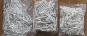
Check the cable route. Are there any sharp corners or areas where the cable has become coiled or bent sharply? Do tie clamps contribute to the appearance of microbends (see Figure 6)?
Make sure that there is no accidental multimode connector in the single-mode path. The manufacturing tolerances for single-mode connectors are much tighter than for multimode connectors: they provide more accurate alignment, and, as a result, the loss of optical power in such a connection is less. In addition, connectors and cords are designed for a limited number of connections/disconnections. A cable or cord that has been connected and disconnected many times begins to dangle in the connector, so that it is no longer possible to ensure the correct relative position of the fibers. An OTDR can detect such problems.
If the failure affects a single device, the problem is often caused by the transmitting port of the active equipment. There may be dirt accumulated inside or the transmitter output power is insufficient. Connect the power meter from the OLTS kit to the port, and then compare the resulting value with the power value for neighboring ports.
Igor Panov is a regional product and partner support manager for Fluke Networks in Russia and the CIS. He can be contacted at