Designs and calculations of power transmission line supports - Location of wires and structural diagrams of supports
Page 4 of 49
In Fig. 1-5 show the basic wiring diagrams adopted in domestic and foreign practice on three-phase current lines with steel and reinforced concrete supports.
Rice. 1-5. Wiring diagrams
Wires can be arranged in one, two or three tiers. An arrangement in one tier (Fig. 1-5, a-e) is usually called horizontal, an arrangement in two or three tiers without horizontal displacement of the wires located above each other (Fig. 1-5, f-j) is called vertical. The arrangement of wires in two or three tiers, in which the wires located above each other have a horizontal displacement A (Fig. 1-5, l-t), is called mixed. When the wires are positioned horizontally, the wires are less likely to jam under uneven ice loads and wind. Therefore PUE. It is recommended that in regions III and IV of ice conditions, preference be given to the horizontal arrangement of wires (all other things being equal); in particularly icy areas, the use of supports with horizontal wires is mandatory. Horizontal arrangement of wires should also be preferred in areas where there is frequent and intense dancing of wires. It must be taken into account that on supports with horizontal wires, the possibility of jamming when the wires are unevenly loaded with ice is excluded only in the absence of cables (Fig. 1-5, a). If the cables are poorly positioned, there is a danger of them intersecting with the wires; To avoid jamming, it is necessary to provide sufficient vertical distances between wires and cables and possibly large displacements in the horizontal direction (Fig. 1-5, b). On single-circuit lines with horizontal wires and without lightning protection cables, pin insulators can be mounted on a single-post support with one crossarm (Fig. 1-5, a). With suspended insulators, to ensure the suspension of the middle wire, the support must be made either two-post (portal - Fig. 1-5, b), or single-post with the upper part of the trunk divided into two branches (the so-called “glass” type support, Fig. 1-5 , V). Double-circuit lines with horizontal wires can be made on portal supports (Fig. 1-5, d) or on single-column supports (Fig. 1-5, e). Supports with a vertical arrangement of wires without horizontal displacement in adjacent tiers can be used according to the PUE on lines with voltages less than 35 kV, usually made with pin insulators (Fig. 1-5, f, g, i). Supports with suspended insulators, single-circuit with a triangular arrangement of wires (Fig. 1-5, h) and double-circuit with a vertical arrangement of wires (Fig. 1-5, j) are often used in foreign practice in countries and areas with no ice. The new edition of the PUE allows for the vertical arrangement of wires on lines with a voltage of 35 kV and higher with sufficient vertical distances between the wires of adjacent tiers (see §1-4). With a mixed arrangement of wires, single-circuit supports with pin insulators are usually made with one insulator secured at the top of the support shaft and two insulators on the traverse (Fig. 1-5, l). If it is necessary to suspend a lightning protection cable, this cable is fixed at the top of the support shaft, and the insulators are attached to the traverses (Fig. 1-5, m). On single-circuit supports with suspended insulators, the wires are located at the vertices of the triangle (Fig. 1-5, n and o). The difference between the shown schemes is the location of the traverses in height in two or three tiers. In domestic practice, single-chain supports with traverses arranged in two tiers are currently used, which are more economical and allow the use of the same traverses for single-chain and double-chain supports (Fig. 1-5, o and c). Double-circuit supports with a mixed arrangement of wires can be made by placing the wires along two inclined straight lines converging upward (diagram or “Christmas tree” type, Fig. 1-5, p), along two straight lines converging downwards (diagram or “reverse herringbone” type) , Fig. 1-5, p), as well as with the arrangement of wires along the vertices of a hexagon (the so-called “barrel” type diagram, Fig. 1-5, c), or along the vertices of two triangles (the so-called Danube type support, Fig. 1-5, t). Of the listed types of double-circuit supports, the most economical are those with wires arranged in a “barrel” pattern. Therefore, in domestic practice, double-chain steel and reinforced concrete supports, as a rule, are made of this type. The disadvantage of double-circuit supports with a multi-tier arrangement of wires compared to single-circuit ones, especially compared to single-circuit supports with a horizontal arrangement of wires, is the increase in the height of the supports. As the height of the supports increases, wind and ice loads increase, and lightning protection conditions worsen. However, double-chain supports, designed taking into account the influence of these factors, have almost the same reliability as single-chain ones.
- Back
- Forward
Arrangement of wires and cables on the support
When choosing the type of support, you must mark the desired location of the wires on the support.
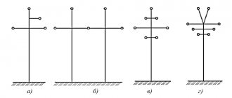
From the point of view of electrical processes in overhead lines, it is desirable to place the wires symmetrically in the corners of an equilateral triangle. But in practice, with this arrangement, it is likely that the wires secured in the garlands of suspended insulators will get caught. It is convenient to use portal-type supports with horizontal wires in one plane, but these supports are expensive. Therefore, the most common is the placement of wires in the corners of an unequal triangle on single-circuit supports (Fig. 2.2a) and on double-circuit ones - in the form of a “barrel” (Fig. 2.2b), “straight tree” (Fig. 2.2c), “reverse tree” (Fig. 2.2d). In special areas with ice and areas with frequent dancing of wires, as well as on overhead lines of 500 kV and above, the wires are placed horizontally. Rice. 2.2. Location of wires on the support According to the PUE, overhead lines with voltages of 110 kV and higher on metal and reinforced concrete supports must be protected along their entire length by lightning protection cables. 35 kV lines are protected by cables only at the approaches to substations (in sections 1–2 km long). 220 kV lines at the approaches to substations (up to 2 km) are protected by two cables.
Lines with wire arrangement according to Fig. 2.2 are protected by one cable (Fig. 2.3a), lines with horizontal wires are protected by two cables (Fig. 2.3b). 220 and 330 kV lines on supports 35–45 m high are sometimes protected by two cables at the approaches to substations, and in some cases (in areas with strong thunderstorm activity) - along the entire length.
With one lightning protection cable, the protective angle should be no more than 300, and with two cables - no more than 200.
Rice. 2.3. Arrangement of cables on the support
The shortest distances between the wire and the cable in the middle of the span are indicated in Table. 3.1.
The designs of reinforced concrete and steel unified supports in single-chain and double-chain versions are shown in Figure B1 of Appendix B. The main dimensions of the supports, their scope and characteristics are in Table. B1 of Appendix B.
When choosing the type of support, you must mark the desired location of the wires on the support.
From the point of view of electrical processes in overhead lines, it is desirable to place the wires symmetrically in the corners of an equilateral triangle. But in practice, with this arrangement, it is likely that the wires secured in the garlands of suspended insulators will get caught. It is convenient to use portal-type supports with horizontal wires in one plane, but these supports are expensive. Therefore, the most common is the placement of wires in the corners of an unequal triangle on single-circuit supports (Fig. 2.2a) and on double-circuit ones - in the form of a “barrel” (Fig. 2.2b), “straight tree” (Fig. 2.2c), “reverse tree” (Fig. 2.2d). In special areas with ice and areas with frequent dancing of wires, as well as on overhead lines of 500 kV and above, the wires are placed horizontally. Rice. 2.2. Location of wires on the support
According to the PUE, overhead lines with voltages of 110 kV and higher on metal and reinforced concrete supports must be protected along their entire length by lightning protection cables. 35 kV lines are protected by cables only at the approaches to substations (in sections 1–2 km long). 220 kV lines at the approaches to substations (up to 2 km) are protected by two cables.
Lines with wire arrangement according to Fig. 2.2 are protected by one cable (Fig. 2.3a), lines with horizontal wires are protected by two cables (Fig. 2.3b). 220 and 330 kV lines on supports 35–45 m high are sometimes protected by two cables at the approaches to substations, and in some cases (in areas with strong thunderstorm activity) - along the entire length.
With one lightning protection cable, the protective angle should be no more than 300, and with two cables - no more than 200.
Rice. 2.3. Arrangement of cables on the support
The shortest distances between the wire and the cable in the middle of the span are indicated in Table. 3.1.
The designs of reinforced concrete and steel unified supports in single-chain and double-chain versions are shown in Figure B1 of Appendix B. The main dimensions of the supports, their scope and characteristics are in Table. B1 of Appendix B.