Main parameter of the transformer
The main characteristic of any transformer is the transformation ratio. It is defined as the ratio of the number of turns in the primary winding to the number of turns in the secondary winding. In addition, this value can be calculated by dividing the corresponding EMF indicators in the windings.
Formula
In the presence of ideal conditions, when there are no electrical losses, the solution to the question of how to determine the coefficient is carried out using the ratio of the voltages at the terminals of each winding. If the transformer has more than two windings, this value is calculated for each winding in turn.
In step-down transformers, the transformation ratio will be above unity; in step-up devices, this indicator ranges from 0 to 1. In fact, this indicator determines how many times the voltage transformer reduces the supplied voltage. It can be used to determine the correct number of turns. This coefficient is determined on all available phases and on each branch of the network. The data obtained is used for calculations, making it possible to identify wire breaks in the windings and determine the polarity of each of them.
You can determine the real transformation ratio of the transformer current using two voltmeters. In transformers with three windings, measurements are made on at least two pairs of windings with the lowest short-circuit current. If some elements of the transformer and branches are covered with a casing, then determining the coefficient becomes possible only for the terminals of the windings brought out.
In single-phase transformers, to calculate the operating transformation ratio, a special formula is used in which the voltage supplied to the primary circuit is divided by the simultaneously measured voltage in the secondary circuit. To do this, you need to know in advance how each indicator is measured.
It is prohibited to connect voltage to the windings significantly higher or lower than the rated value specified in the transformer passport. This will lead to an increase in measurement errors due to losses of current consumed by the measuring device to which the three-phase transformer is connected. In addition, the measurement accuracy is affected by the no-load current. For most devices, a special table has been developed, which contains fairly accurate data that can be used in calculations.
Measurements should be carried out with voltmeters with an accuracy class of 0.2-0.5. A simpler and faster determination of the coefficient is possible with the help of special universal devices that make it possible to do without the use of extraneous AC voltage sources.
Verification
carried out according to the document GOST 8.216-2011 “GSI. Voltage transformers. Verification methodology."
— measuring laboratory voltage transformer of the NLL-10 series (registration number in the Federal Information Fund 46942-10);
— comparison device KNT-03 (registration number in the Federal Information Fund 24719-03);
— load magazine MP 3025 (registration number in the Federal Information Fund 22808-07).
It is allowed to use similar verification tools that ensure the determination of the metrological characteristics of the verified measuring instruments with the required accuracy.
The verification mark is applied to the verification certificate in the form of an imprint of the verification mark.
| Transformer | Rated voltage of windings, kV | Rated voltage, kA in accuracy class | Maximum power limit | N, mm | Weight, kg | ||||
| VN | NN (main) | NN (additional) | 0,5 | 1,0 | 3,0 | ||||
| STMI-6 | 6 | 0.1 | 0.1/3 | 75 | 150 | 300 | 630 | 400 | 67 |
| NTMI-10 | 10 | 0.1 | 0.1/3 | 150 | 300 | 500 | 1000 | 490 | 87 |
Calculation of current transformers 10 kV. Everything will be fine
printed on the title page of the voltage transformer passport. Completeness of the measuring instrument
Expert opinion
It-Technology, Electrical power and electronics specialist
Ask questions to the “Specialist for modernization of energy generation systems”
PKU 6 kV and PKU 10 kV Commercial metering point from the manufacturer The maximum maximum power is the maximum power of the transformer, which is several times higher than the rated power, but at which the transformer can operate with permissible heating of the windings. Ask, I'm in touch!
What is transformation ratio
The transformer does not change one parameter to another, but works with their values. However, it is called a converter. Depending on the connection of the primary winding to the power source, the purpose of the device changes.
These devices are widely used in everyday life. Their goal is to supply a home device with power that corresponds to the nominal value specified in the passport of this device. For example, the network voltage is 220 volts, the phone battery is charged from a 6 volt power source. Therefore, it is necessary to reduce the mains voltage by 220:6 = 36.7 times, this indicator is called the transformation ratio.
To accurately calculate this indicator, you need to remember the design of the transformer itself. Any such device has a core made of a special alloy and at least 2 coils:
- primary;
- secondary.
The primary coil is connected to the power source, the secondary coil is connected to the load, there can be 1 or more of them. A winding is a coil consisting of an electrical insulating wire wound on a frame, or without it. A complete turn of the wire is called a turn. The first and second coils are installed on the core, with its help energy is transferred between the windings.
For power transformer
Transformers can be step-up and step-down, to determine this you need to find out the transformation ratio , with its help you can find out which transformer. If the coefficient is less than 1, then the transformer is step-up (this can also be determined by the values; if there is more in the secondary winding than in the primary, then it is step-up), and vice versa, if K>1, then it is step-down (if there are fewer turns in the primary winding than in the secondary).
Formula for calculating the transformation ratio
Where:
- U1 and U2 - voltage in the primary and secondary windings,
- N1 and N2 - number of turns in the primary and secondary windings,
- I1 and I2 - current in the primary and secondary windings.
Current transformer
Formula for calculating the CT transformation ratio:
The coefficient values are usually very large compared to a power transformer. The values can be as presented in the table:
Let's determine the coefficient. transformations: let's take a CT with the values that are highlighted in the table 600/5 = 120. You can also take any transformer 750/5 = 150; 800/2 = 400, etc.
Voltage transformer
Formula for calculating the VT transformation ratio:
Let's calculate the transformation ratio for the VT shown in the photo below:
You need to take the voltage of the primary winding (red arrow) and divide it by the voltage of the secondary winding (yellow arrow). 35000/100 = 350.
Electric meter transformation ratio
The value of the transformation ratio is widely used for electricity metering devices. This data is necessary for the correct selection of an electric meter and further calculations of real energy consumption. For this purpose, an additional indicator is used - the calculated accounting coefficient.
In order to determine this value, readings are taken from the electricity meter and multiplied by the transformation ratio of the connected transformer device. For example, when solving the problem of how to find the desired indicator, 60 kW/h needs to be multiplied by a coefficient equal to 20 (30, 40 or 60). The result of multiplication is 60 x 20 = 1200 kW/h. The resulting value will be the actual energy consumption.
There are different types of metering devices. According to their principle of operation, they can be single- or three-phase. They are not connected directly; a current transformer must be connected between them in the circuit. Some meter designs suggest the possibility of direct connection. In networks with voltages up to 380 volts, 5-20 ampere meters are used. The meter receives electricity in its pure form, with a constant value.
Currently, induction meters are used, which are gradually being replaced by electronic models. They are considered obsolete because they cannot account for consumed electricity at different tariffs. In addition, they cannot transmit data over a remote distance. Therefore, they are being replaced by electronic meters capable of directly converting the incoming current into certain signals. These designs have no rotating parts, which significantly increases their reliability and durability. The transformation ratio of the meters has a direct impact on the accuracy of the received data.
Checking the thermal resistance condition:
This check must comply with the following requirement:
The conditions have been met. Calculation of current transformers 10 kV
As you can see, there is nothing complicated here, and anyone who can handle a calculator can handle this work. Don't be afraid to take on seemingly difficult things. They seem complicated only at first glance. And if you think about it and figure it out, it turns out that there is nothing super complicated about them. Take it, try it, and everything will work out for you. Good luck…
You can download images in PDF format using the links “Plan” “Scheme”.
Expert opinion
It-Technology, Electrical power and electronics specialist
Ask questions to the “Specialist for modernization of energy generation systems”
Startbase - System for activating and increasing the effectiveness of the innovation process - Products / Product Review / Digital current and voltage transformer 6-10 (kV) Optical transformers have a very high cost, their economic profitability decreases with the operating voltage class. Ask, I'm in touch!
How to calculate the transformation ratio
The transformation coefficient “k” is the ratio of the voltage U1 at the ends of the primary winding of the transformer to the voltage U2 at the terminals of its secondary winding, determined at no-load (when there are several secondary windings, then there are also several coefficients k, they are determined in this case one by one). This ratio is taken to be equal to the ratio of the numbers of turns in the corresponding windings.
The value of the transformation ratio is easily calculated by dividing the EMF of the windings of the transformer under study: EMF of the primary winding by EMF of the secondary.
The transformation ratio is very important as the value by which the secondary winding is brought to the primary. In operating conditions, the voltage transformation ratio, which is understood as the ratio of the rated voltages of the transformer, is of great importance.
For single-phase transformers there is no difference between the transformation coefficients of EMF and voltage, but in three-phase transformers they should be strictly distinguished from each other.
Ideally, there are no power losses (due to Foucault currents and heating of the winding conductors) in the transformer, therefore the transformation ratio for ideal conditions is calculated by simply dividing the voltages at the winding terminals. But nothing is perfect in the world, so sometimes it is necessary to resort to measurements.
In reality, we are always dealing with a step-up or step-down transformer. Voltage transformers that increase the transformation ratio are always less than one (and more than zero), while voltage transformers that increase the transformation ratio are always less than one. That is, the transformation ratio indicates how many times the current of the secondary winding under load differs from the current of the primary winding, or how many times the voltage of the secondary winding is less than that supplied to the primary winding.
For example, the TP-112-1 step-down transformer has a transformation ratio of 7.9/220 = 0.036 according to its passport, which means that the rated current (according to the passport) of the secondary winding of 1.2 amperes corresponds to a primary winding current of 43 mA.
Knowing the transformation ratio, measuring it, for example, with two voltmeters at idle, you can verify the correct ratio of the number of turns in the windings. If there are several clamps, then measurements are carried out on each branch. Measurements of this kind help to detect damaged windings and determine their polarities.
There are several ways to determine the transformation ratio:
a way to directly measure voltages with voltmeters;
AC bridge method (for example, a portable device of the “coefficient” type for analyzing the parameters of three-phase and single-phase transformers);
according to the passport of this transformer.
To find the real transformation ratio, two voltmeters are traditionally used. The nominal transformation ratio is calculated by dividing the voltage values measured at no-load (they are indicated in the passport for the transformer).
If a three-phase transformer is being tested, then measurements should be carried out for two pairs of windings with the lowest short-circuit current. When the transformer has terminals, some of which are hidden under the casing, the value of the transformation ratio is determined only for those ends that are accessible from the outside for connecting devices.
If the transformer is single-phase, then the operating transformation ratio can be easily calculated by dividing the voltage applied to the primary winding by the voltage on the secondary winding measured by a voltmeter at the same moment (with a load connected to the secondary circuit).
In relation to three-phase transformers, this operation can be performed in various ways. The first way is to supply a three-phase voltage from a three-phase network to the high-voltage winding, or the second way is to supply a single-phase voltage to only one of the three high-voltage windings, without output or with the zero point output. In each option, linear voltages are measured at the same terminals of the primary and secondary windings.
In each case, it is impossible to apply a voltage to the windings significantly exceeding the nominal value specified in the passport, because then the measurement error will be high due to losses even at no-load.
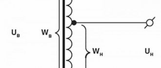
What determines the magnitude of electromotive force?
The magnitude of this EMF (U2) depends on the voltage U1 and the ratio of the turns of the primary and secondary windings, that is: U2=U1 (N2/N1).
In this case, the ratio of the number of turns of the secondary and primary windings Кт of a given transformer is denoted by n: n= N2/ N1. Thus, the transformation ratio is a value that shows the scaling characteristic of the TR relative to some parameter of the electrical circuit.
For power transformers, GOST 16110–82 defines the transformation ratio as “the ratio of the voltages at the terminals of two windings in no-load mode” and “is taken equal to the ratio of the numbers of their turns”
Estimated accounting factor
To clarify the real level of electrical energy consumption, it is necessary to take readings from the electric meter, and then multiply them by CT.
In practice, the CT of a transformer that reduces voltage at home is 20 units, so the data from the meter must be multiplied by this figure, as a result of which the actual electrical energy consumption will be obtained.
How to use an online calculator to calculate a transformer step by step
Preparing source data in 6 simple steps
Step #1. Specifying the core shape and cross-section
Cores made from W-shaped plates have the best distribution of magnetic flux. The ring shape of U-shaped components has great resistance.
To carry out the calculation, you need to indicate the shape of the core according to the type of plate (by clicking on the point) and its measured linear dimensions:
- The width of the plate under the coil with winding.
- Thickness of the assembled package.
Paste this data into the appropriate table cells.
Step #2. Voltage selection
The transformer is created as a step-up, step-down (which is in principle reversible) or separating structure. In any case, you need to indicate what voltages you need on its primary and secondary windings in volts.
Fill in the indicated cells.
Step #3. AC signal frequency
By default, the standard household network value is set to 50 hertz. If necessary, it must be changed to that required by another calculation. But, this technique is not intended for high-frequency transformers used in switching power supplies.
They are created from other core materials and calculated in different ways.
Step #4. Efficiency
For conventional models of dry-type transformers, the efficiency depends on the applied electrical power and is calculated as an average value.
But, you can adjust its value manually.
Step #5. Magnetic inductance
The parameter determines the dependence of the magnetic flux on the geometric dimensions and shape of the conductor through which the current flows.
By default, the average parameter of 1.3 Tesla is adopted for calculating transformers. It can be adjusted.
Step #6. Current Density
The term is used to select the winding wire according to operating conditions. The average value for copper is 3.5 amperes per square millimeter of cross-section.
To operate the transformer in conditions of increased heating, it should be reduced. For forced cooling or reduced loads, it is permissible to increase. However, 3.5 A/mm kV is quite suitable for household devices.
Performing online transformer calculations
After filling in the cells with the original data, click on the “Calculate” button. The program automatically processes the entered data and displays the calculation results in a table.
Online calculator (link will open in a new tab)
Different types of transformers and their ratios
Although the converters are not much different from each other structurally, their purpose is quite broad. There are the following types of transformers, in addition to those discussed:
- power;
- autotransformer;
- pulse;
- welding;
- dividing;
- coordinating;
- peak transformer;
- dual throttle;
- transfluxor;
- rotating;
- air and oil;
- three-phase.
A feature of the autotransformer is the absence of galvanic isolation; the primary and secondary windings are made of one wire, and the secondary is part of the primary. Pulse scales short pulsed square wave signals. The welding machine operates in short circuit mode. Separators are used where special safety in electrical engineering is needed: wet rooms, rooms with a large number of metal products, etc. Their k is basically 1.
The peak transformer converts sinusoidal voltage into pulse voltage. A dual choke is two double coils, but in terms of its design features it is classified as a transformer. The transfluxor contains a core made of a magnetic circuit with a high residual magnetization, which allows it to be used as a memory. Rotator transmits signals to rotating objects.
Air and oil transformers differ in the method of cooling. Oil-based ones are used for scaling high power. Three-phase are used in a three-phase circuit.
More detailed information can be found about the current transformer transformation ratio in the table.
Rated secondary load, V351015203040506075100
| Coefficient, n | Nominal limiting factor | ||||||||||
| 3000/5 | 37 | 31 | 25 | 20 | 17 | 13 | 11 | 9 | 8 | 6 | 5 |
| 4000/5 | 38 | 32 | 26 | 22 | 20 | 15 | 13 | 11 | 10 | 8 | 6 |
| 5000/5 | 38 | 29 | 25 | 22 | 20 | 16 | 14 | 12 | 11 | 10 | 8 |
| 6000/5 | 39 | 28 | 25 | 22 | 20 | 16 | 15 | 13 | 12 | 10 | 8 |
| 8000/5 | 38 | 21 | 20 | 19 | 18 | 14 | 14 | 13 | 12 | 11 | 9 |
| 10000/5 | 37 | 16 | 15 | 15 | 14 | 12 | 12 | 12 | 11 | 10 | 9 |
| 12000/5 | 39 | 20 | 19 | 18 | 18 | 12 | 15 | 14 | 13 | 12 | 11 |
| 14000/5 | 38 | 15 | 15 | 14 | 14 | 12 | 13 | 12 | 12 | 11 | 10 |
| 16000/5 | 36 | 15 | 14 | 13 | 13 | 12 | 10 | 10 | 10 | 9 | 9 |
| 18000/5 | 41 | 16 | 16 | 15 | 15 | 12 | 14 | 14 | 13 | 12 | 12 |
Almost all of the devices listed have a core for transmitting magnetic flux. The flux appears due to the movement of electrons in each of the turns of the winding, and the current strengths should not be equal to zero. The current transformation ratio also depends on the type of core:
- core;
- armored.
In an armor core, magnetic fields have a greater effect on scaling.
Dependence of efficiency on load factor
During the operation of any equipment, its efficiency is important. For transformer equipment in a substation or factory, this is the relationship between the voltage coming from the network and the voltage supplied to consumers:
Efficiency = P2/P1
Essentially, it is the voltage conversion efficiency.
In practice, a more precise formula is used:
Efficiency = 1- (∑P – (P2 + ∑P)), where:
∑P – sum of losses on windings and iron.
Losses are determined based on short circuit (Pk) and no-load (P) experiments.
The efficiency reaches its maximum value if the losses in steel and windings are equal.
Since the ratio of no-load losses to the output voltage (P/P1) is 0.25-0.4, the maximum efficiency value is achieved at a load factor of 0.5-0.7.
How to determine the load factor of a transformer in practice? There are catalogs and standards with tables Rk and R.
To calculate the optimal value, the formula is used:
βopt = √P/Pk.
This is approximately 0.45-0.5.
When the indicator decreases or exceeds the efficiency, it decreases, which entails an increase in operating costs.
If the currents are small, useful work is equal to losses. When the optimal load is exceeded, the winding wires heat up and the core becomes saturated, the converter heats up. During operation, it is most often possible to regulate the load level in such a way as to obtain the optimal efficiency value.
How to determine this indicator in power transmission circuits
When transferring energy to a specific load, they try to match the power of the load in the secondary circuit with the power extracted by the transformer from the circuit of its primary winding, that is, from the source. Such matching can be achieved using ballast resistances in the secondary circuits, or you can use a matching transformer for this.
The power ratio in this case will be
Relationship S1 = S2 + ΔS
where S1 is the power consumed by the transformer from the network and S2 is the power supplied by the transformer to the load;
ΔS - power losses in the transformer itself - they are usually found to be equal to 1-2% of the power.
Neglecting these small losses of the transforming device, we obtain the dependences for the powers
Formulas
S1=U1*I1= U21/Z1
S2=U2*I2= U22/Z2
where Z1 is the input resistance of the transformer circuit with a load relative to the primary circuit,
Z2 is the input resistance of the transformer load circuit connected to the secondary winding.
Since the circuits are matched, then
Formula S1=S2→U12/Z1 = U22/Z2→ U12/U22 = Z1/Z2=nz=nu2
The value of another indicator is obtained, which is called the resistance transformation ratio, and this transformation ratio is equal to the ratio of the squares of the voltages on the primary winding and on the secondary.
How to determine experimentally?
In real practical cases, it is not always possible to find the transformation coefficient purely analytically, which is not helped even by the use of calculators. For example, transformers with several windings.
The transformation ratio of a three-phase transformer, generally speaking, is not one, but several, since a three-phase transformer contains several secondary windings that are wound on one core.
Or when we have a transformer in front of us, but we don’t know the exact number of turns in the windings.
note
Therefore, there are experimental determination methods based on measuring the voltage at the input of the transformer and the voltage on the secondary windings. Such measurements must be made at idle, and simultaneously on the primary and secondary windings. From them you will find the required transformation coefficients. The found value will serve as the basis for further calculations.
Device and principle of operation
In static equipment, which is designed to convert frequency and voltage, as well as the number of phases, there are no moving structural elements, which eliminates the occurrence of mechanical losses. But in the process of transferring the load from the primary circuit to the secondary, not all the power reaches the energy receiver, which acts as the end consumer.
Electromagnetic static equipment without rotating parts converts energy and operates from the mains. The power unit is a device, the main elements of which are a steel magnetic circuit of a rod or armored design and coils - unconnected electrically insulated wires.
Transformer equipment is of single-phase and multi-phase types, respectively, consisting of two or more circuits. Depending on the type of design, devices with armored, rod or armored rod magnetic circuits are distinguished. The operating principle of the equipment using the example of a simple single-phase device:
- The first coil is connected to the alternating current source, and the secondary circuit is connected to the electricity receiver (end consumer).
- Alternating current passes through the turns of the primary winding, and its value corresponds to the value of the load I1.
- The magnetic flux F penetrates both circuits and induces an electromotive force in the conductors.
- When the second circuit is connected to a source of electricity, a load current I2 arises in the circuit under the influence of EMF.
- The transformer unit operates at idle speed if no load is applied to the secondary winding of the device.
Peculiarities
The value of the electromotive force indicator is closely related to the number of turns of wire on the coils. The ratio of the EMF in the windings, called the transformation ratio, corresponds to the number of turns of the copper coils. By changing the number of turns in the circuits, you can regulate the voltage in the electricity receiver.
The windings are interconnected by magnetic lines, and the degree of their interconnection is affected by the proximity/distance of the coils. Due to the change in current strength in the first winding, both circuits are penetrated by a magnetic flux, constantly changing its magnitude and direction. The connection of the ends of the secondary winding with the receiver transmits current to it, and the means of energy transmission is an alternating magnetic flux - the coils are not connected to each other galvanically.
It is also worth considering that you cannot open the secondary winding of the transformer.
What is idle mode
One of the most used electrical devices is the transformer. This equipment is used to change the magnitude of electrical voltage. Let's consider the features of the transformer no-load mode, taking into account the rules for determining characteristics for various types of devices.
The transformer consists of primary and secondary windings located on the core. When voltage is applied to the input coil, a magnetic field is formed, inducing a current in the output winding. The difference in characteristics is achieved due to the different number of turns in the input and output coils.
The idle mode is understood as the state of the device in which, when an alternating current is supplied to the input coil, the output coil is in an open state. This situation is typical for a unit connected to the mains, provided that the load to the output circuit has not yet been turned on.
Short circuit mode
During the experiment you can find:
- no-load electric current (measured with an ammeter) - usually its value is small, no more than 0.1 of the rated current of the first winding;
- power lost in the magnetic circuit of the device (or in other words, losses in steel);
- voltage transformation indicator - approximately equal to the value in the primary circuit divided by that for the secondary (both values are data from voltmeters);
- Based on the results of measurements of current, power and voltage of the primary electrical circuit, the power factor can be calculated: the power is divided by the product of two other quantities.
Using commercial metering points
When operating the PCU, a number of requirements must be observed, including:
- The installation height does not exceed 1000 meters above sea level.
- The air does not contain explosive flammable impurities or large amounts of pollutants.
- Average daily temperatures range from +50 to -40 (short-term -45) degrees Celsius
- The ability to withstand mechanical stress is determined according to GOST 17516.1 in category M2.
Installation of PKU is carried out only by specialists with appropriate qualifications and practical experience working on equipment of this type. Immediately before starting the installation you must:
- Coordinate construction work with technical documentation.
- Check the delivery package and make sure there is no damage that may have occurred during storage or transportation.
Installation work must be carried out in full compliance with all the rules specified in:
To ensure correct operation of the device, it is necessary to carry out regular inspections in accordance with the technical inspection regulations. In this case, the removal of equipment from the network is determined by the specification of the work being carried out.
Expert opinion
It-Technology, Electrical power and electronics specialist
Ask questions to the “Specialist for modernization of energy generation systems”
Features of operation When calculating the short circuit current, the most severe mode is taken into account, with minimal resistance to the site of the alleged damage. Ask, I'm in touch!
How is the idle test performed?
When conducting an idle test, it becomes possible to determine the following characteristics of the unit:
- transformation ratio;
- power loss in steel;
- parameters of the magnetizing branch in the equivalent circuit.
For the experiment, a rated load is applied to the device.
When conducting an idle test and calculating characteristics based on this technique, it is necessary to take into account the type of device.
In this state, the transformer has zero useful power due to the absence of electric current at the output coil. The applied load is converted into heat loss on the input coil I02×r1 and magnetic core loss Pm. Due to the insignificance of heat losses at the input, they are not taken into account in most cases. Therefore, the total value of no-load losses is determined by the magnetic component.
The following are the features of calculating characteristics for various types of transformers.
For single phase transformer
The no-load test for a single-phase transformer is carried out with the connection:
- voltmeters on the primary and secondary coils;
- wattmeter on the primary winding;
- ammeter at the input.
The devices are connected according to the following scheme:
To determine the no-load current Iо, use an ammeter reading. It is compared with the rated current value using the following formula, resulting in a percentage:
Iо% = I0×100/I10.
To determine the transformation ratio k, determine the value of the rated voltage U1н according to the readings of the voltmeter V1 connected to the input. Then, using the voltmeter V2 at the output, the value of the rated voltage U2O is taken.
The coefficient is calculated using the formula:
K = w1/w2 = U1н/ U2О.
The amount of loss is the sum of the electrical and magnetic components:
P0 = I02×r1 + I02×r0.
But, if we neglect electrical losses, the first part of the sum can be excluded from the formula. However, an insignificant amount of electrical losses is typical only for low-power equipment. Therefore, when calculating the characteristics of powerful units, this part of the formula should be taken into account.
No-load losses for transformers with a power of 30-2500 kVA
For three-phase transformer
Three-phase units are tested according to a similar scheme. But the voltage is supplied separately for each phase, with the appropriate installation of voltmeters. You will need 6 units of them. You can conduct an experiment with one device, connecting it to the required points one by one.
When the rated voltage of the winding electric current is more than 6 kV, 380 V is supplied for testing. The high-voltage mode for conducting the experiment will not allow achieving the necessary accuracy for determining the indicators. In addition to accuracy, the low-voltage mode ensures safety.
The following scheme applies:
The operation of the device in idle mode is determined by its magnetic system. If we are talking about a type of device similar to a single-phase transformer or an armored rod system, the closure of the third harmonic component for each phase will occur separately, with a value increasing to 20 percent of the active magnetic flux.
As a result, an additional EMF arises with a fairly high rate - up to 60 percent of the main one. There is a danger of damage to the insulating layer of the coating with the possibility of failure of the device.
It is preferable to use a three-rod system, when one of the components will not pass through the core, with a circuit through air or another medium (for example, oil), with low magnetic permeability. In such a situation, the development of a large additional EMF, leading to serious distortions, will not occur.
For welding transformer
For welding transformers, idling is one of the modes of their constant use in operation. During welding in operating mode, the second winding is short-circuited between the electrode and the metal of the part. As a result, the edges melt and a permanent connection is formed.
After finishing work, the electrical circuit is broken and the unit goes into idle mode. If the secondary circuit is open, the voltage in it corresponds to the EMF value. This component of the power flow is separated from the main one and is closed through the air.
To avoid danger to humans when the machine is idling, the voltage value should not exceed 46 V. Considering that in some models the value of these characteristics exceeds the specified value, reaching 70 V, the welding unit is equipped with a built-in performance limiter for idle mode.
The blocking is activated within a time not exceeding 1 second from the moment the operating mode is interrupted. An additional protective measure is a grounding device for the welding unit housing.
Sources
- https://dzgo.ru/osveshchenie/koefficient-transformacii-transformatora.html
- https://odinelectric.ru/equipment/chto-takoe-koeffitsient-transformatsii-transformatora
- https://OFaze.ru/teoriya/koeffitsient-transformatsii
- https://ElektroKlub-nn.ru/osveshchenie/koefficient-transformacii-schetchika.html
- https://orenburgelectro.ru/drugoe/chto-takoe-koeffitsient-transformatsii-sovety-elektrika.html
- https://OFaze.ru/teoriya/holostoj-hod-transformatora
- https://ElectroInfo.net/transformatory/rezhim-holostogo-hoda-dlja-transformatorov.html
Calculator
To simplify calculations, it is convenient to use an online calculator. The program algorithm allows you to calculate the energy losses of a transformer without complex formulas. But the results obtained should be considered as indicative. The following data is used to enter:
- the value Snom (kVA) is taken from the technical data sheet of the device;
- enter the value Ркз – reference (passport) parameter (kW);
- select Pхх in the technical documentation of the device (kW);
- indicate the load current Iхх in percentage terms (%);
- indicate the voltage Ucz - reference information (%);
- enter the load factor K in relative units;
- indicate the operating time of the device with maximum load Tm (hour);
- the annual number of operating hours of the unit Tg (hour) is taken from the actual operating mode of the equipment;
- average CO tariff for active electricity in the billing period (RUB/kW*hour).
After entering the data, the program calculates the required values.
Since energy losses lead to an increase in the consumption of materials and funds, they cause an increase in the cost of electricity. Minimizing the loss of unproductive energy consumption of power units makes it possible to design devices with maximum efficiency. By applying in practice methods for calculating active power losses of transformer units, it is possible to determine the cost-effectiveness of equipment operation and the need to install compensating equipment in closed circuits.
Types of current transformers
It is necessary to select a device suitable for the mains voltage or specific work based on classification according to various criteria.
Purpose
There are such transformers:
- measuring - measure the parameters of the circuit;
- protective – prevent overloads and equipment failure;
- intermediate – connected to a circuit with relay protection, equalizing currents in differential protection circuits;
- laboratory ones are highly accurate.
Laboratory models have higher conversion factors.
Installation type
For a private house or apartment, you can choose a device that can be installed indoors or outdoors. Some modifications are built into the equipment and are also placed on the bushing. Portable models are used for measurements and laboratory tests.
Primary winding design
There are bus, single-turn (with a rod) and multi-turn (with a coil, loop-type winding and figure-of-eight) devices.
Insulation type
The following converters are available:
- dry insulation - based on cast epoxy, porcelain or bakelite;
- paper-oil – standard or condenser;
- gas-filled - inside there is inorganic SF6 gas with a high breakdown voltage;
- compound - inside there is a filling of thermoactive and thermoplastic resin.
The compound has the highest moisture resistance.
Depending on the number of transformation stages, you can select single-stage and cascade models. The entire line has an operating voltage of more than 1000 V.