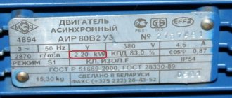
Basic parameters of the electric motor
- Motor power
- Rated speed
- Efficiency
- Motor torque
- Rotor moment of inertia
- Rated voltage
- Electrical time constant
Motor power
Motor power is the useful mechanical power at the motor shaft.
Mechanical power
Power is a physical quantity that shows how much work a mechanism does per unit of time.
- where P
– power,
W
, - A
– work,
J
, - t
—time,
s
Work is a scalar physical quantity equal to the product of the projection of force and direction F
and the path
s
traversed by the point of application of the force.
- where s
– distance,
m
For rotational movement
- where θ – angle, rad
- where ω – angular frequency, rad/s
,
In this way, you can calculate the value of mechanical power on the shaft of a rotating electric motor
Reference: Nominal value is the value of a parameter of an electrical product (device), specified by the manufacturer, at which it should operate, which is the initial value for calculating deviations.
Rotation frequency
- where n
is the rotation speed of the electric motor,
rpm
Rotor moment of inertia
The moment of inertia is a scalar physical quantity, which is a measure of the inertia of a body in rotational motion around an axis, equal to the sum of the products of the masses of material points by the squares of their distances from the axis
- where J
is the moment of inertia,
kg∙m2
, - m
—mass,
kg
Reference: In the English system of measures, the moment of inertia is measured in ounce-force-inch (oz∙in∙s2) 1 oz∙in∙s2 = 0.007062 kg∙m2 (kg∙m2)
The moment of inertia is related to the moment of force by the following relation
- where ε – angular acceleration, s-2
Reference: Determination of the moment of inertia of the rotating part of the electric motor is described in GOST 11828-86
Electric motor efficiency
The efficiency of an electric motor is a characteristic of the machine’s efficiency in converting electrical energy into mechanical energy.
- where η is the efficiency of the electric motor,
- P1
- supplied power (electric),
W
, - P2
- useful power (mechanical),
W
- Wherein
losses in electric motors
- due to:
- electrical losses - in the form of heat as a result of heating current-carrying conductors;
- magnetic losses - losses due to magnetization reversal of the core: losses due to eddy currents, hysteresis and magnetic aftereffects;
- mechanical losses - friction losses in bearings, ventilation, brushes (if any);
- additional losses - losses caused by higher harmonics of magnetic fields arising due to the gear structure of the stator, rotor and the presence of higher harmonics of the magnetomotive force of the windings.
Electric motor efficiency can vary from 10 to 99% depending on the type and design.
The International Electrotechnical Commission defines the efficiency requirements for electric motors. According to the IEC 60034-31:2010 standard, four efficiency classes are defined for synchronous and asynchronous motors: IE1, IE2, IE3 and IE4.
Rated voltage
Rated voltage is the voltage for which the network or equipment is designed and to which their operating characteristics are related.
Electrical time constant
The electrical time constant is the time, counted from the moment a direct voltage is applied to the electric motor, during which the current reaches a level of 63.21% (1-1/e) of its final value.
- where is the time constant, s
Motor torque
Torque (synonyms: torque, torque, moment of force) is a vector physical quantity equal to the product of the radius of the vector drawn from the axis of rotation to the point of application of the force and the vector of this force.
- where M
– torque,
Nm
; - F
– force,
N
; - r
– radius vector,
m
Help: Nominal torque Mnom, Nm, is determined by the formula
- where Pnom
is the rated power of the engine,
W
, - nnom
- rated speed,
min-1
Initial starting torque is the torque of the electric motor at start-up.
Help: In the English system of measures, force is measured in ounce-force (oz, ozf, ounce-force) or pound-force (lb, lbf, pound-force) 1 oz = 1/16 lb = 0.2780139 N (N) 1 lb = 4.448222 N (N)
torque is measured in ounce-force per inch (oz∙in) or pound-force per inch (lb∙in)
1 oz∙in = 0.007062 Nm (Nm) 1 lb∙in = 0.112985 Nm (Nm)
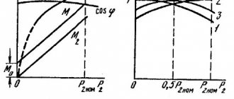
Mechanical characteristics
The mechanical characteristic of the engine is a graphically expressed dependence of the shaft speed on the electromagnetic torque at a constant supply voltage.
2.8. Mechanical characteristics of an asynchronous motor
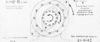
The mechanical characteristic is usually understood as the dependence of the rotor speed as a function of the electromagnetic torque n = f(M). This characteristic (Fig. 2.15) can be obtained using the dependence M = f(S) and recalculating the rotor speed at different slip values.
Rice. 2.15
Since S = (n0 - n) / n0, hence n = n0(1 - S). Let us recall that n0 = (60 f) / p is the rotation frequency of the magnetic field.
Section 1-3 corresponds to stable operation, section 3-4 – unstable operation. Point 1 corresponds to the ideal idle speed of the engine when n = n0. Point 2 corresponds to the nominal operating mode of the engine, its coordinates are Mn and nn. Point 3 corresponds to the critical moment Mcr and the critical rotation speed ncr. Point 4 corresponds to the starting torque of the engine Mstart. The mechanical characteristic can be calculated and constructed using the passport data. Point 1:
n0 = (60 f) / p, where: p – number of pole pairs of the machine; f – network frequency.
Point 2 with coordinates nn and Mn. The rated rotation speed nн is specified in the passport. The rated torque is calculated using the formula:
here: Рн – rated power (shaft power).
Point 3 with coordinates Mkr nkr. The critical moment is calculated using the formula Mkr = Mn λ. The overload capacity λ is specified in the motor passport ncr = n0 (1 - Skr), , Sn = (n0 - nn) / n0 – nominal slip.
Point 4 has coordinates n=0 and M=Mstart. The starting torque is calculated using the formula
Mstart = Mn λstart, where: λstart – the multiplicity of the starting torque is specified in the passport.
Asynchronous motors have a rigid mechanical characteristic, because The rotor speed (section 1–3) depends little on the load on the shaft. This is one of the advantages of these engines.
Application areas of electric motors
Electric motors are the largest consumers of electricity in the world, accounting for about 45% of all electricity consumed.
- Electric motors are used everywhere, the main areas of application are:
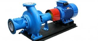
- industry: pumps, fans, compressors, conveyors, driving force for other machines, etc.
- construction: pumps, fans, conveyors, elevators, heating, ventilation and air conditioning systems, etc.
- consumer devices: refrigerators, air conditioners, personal computers and laptops (hard drives, fans), vacuum cleaners, washing machines, mixers, etc.
| ED1 | Functions | Areas of use |
| Rotating electric motors | Pumps | Water supply and wastewater systems |
| Chilled or heated water pumping systems, heating systems, HVAC2, irrigation systems | ||
| Sewage systems | ||
| Pumping of petroleum products | ||
| Fans | Supply and exhaust ventilation, HVAC2, fans | |
| Compressors | Ventilation systems, refrigeration and freezing units, HVAC2 | |
| Accumulation and distribution of compressed air, pneumatic systems | ||
| Gas liquefaction systems, natural gas pumping systems | ||
| Rotate, blend, move | Rolling mill, machines: processing of metal, stone, plastic | |
| Pressing equipment: processing of aluminum, plastics | ||
| Textile processing: weaving, washing, drying | ||
| Mixing, shaking: food, paints, plastics | ||
| Transport | Passenger elevators, escalators, conveyors | |
| Freight elevators, cranes, hoists, conveyors, winches | ||
| Transport means: trains, trams, trolleybuses, cars, electric cars, buses, motorcycles, bicycles, rack railway, cable car | ||
| Angular movements (stepper motors, servo motors) | Valves (open/close) | |
| Servo (position setting) | ||
| Linear motors | Open close | Valves |
| Sorting | Production | |
| Grab and move | Robots |
Note:
- ED - electric motor
- HVAC - heating, ventilation and air conditioning systems
The torque of the gearbox is
Gearbox torque - what does it mean?
There is a generally accepted unit for measuring torque - Newton - meters. That is, if you attach any rod one meter long to the output shaft of the gearbox, then the drive must remain operational with a load at the end of this rod equal to 1 Newton. It is not difficult to guess that the closer to the axis of the output shaft the load is applied, the greater the torque the gearbox can withstand. To simplify calculations, you can convert Newton's force into the force created by a kilogram. The force of 1 kilogram is equal to 9.81 Newton.
Let's look at the example of a cylindrical two-stage gearbox PM-650. Let's take the most common gear ratio - 31.5, input shaft speed - 1500 per minute, operating mode - 100% load. Structurally, this gearbox has a maximum permissible torque under the specified conditions equal to 5116 N.m. What does this mean? This suggests that with a radius of, say, a drum of 1 meter, mounted on the output shaft, the PM-650 gearbox will withstand a load of 5116 Newtons or lift a load of 520 kg. Accordingly, if the radius of the drum is 0.5 meters, then the load allowed is 10232 N.m. or 1040 kg. It is not difficult to guess that the torque created in the mechanism is determined by the product of the force and the length of the lever.
What is the permissible torque of the gearbox for?
In any mechanism or equipment, the gearbox serves as an intermediate link between the engine and the actuator unit. What and why is it needed? An electric motor, having any speed and power, only indirectly reflects the ability of the drive to withstand the load created by the mechanism. In practice, the engine rarely transmits rotation directly to the final unit or device, since during operation the generated thrust, which is created due to the gear ratio, is much more important. All this is determined at the stage of selecting the size of the gearbox.
Gearbox torque
Torque of industrial gearboxes
Manufacturers offer a wide range of electric motors and gearboxes for industrial use. But not each of them is the optimal or even suitable choice for a particular situation.
Users need to select the electric motor for their product based on the basic operating mode. When choosing a gearbox, the type, dimensions, kinematic diagram, and gear ratio are important. One of the main technical characteristics is torque. It allows the receiving device to increase torque and rotate under the action of a new one.
The following torques are distinguished in particular:
- M2 - rotating on the output shaft;
- Mn2 - nominal. This is the most important parameter. The reducer can transmit it for a long time without interruption;
- M2max - maximum torque at constant or variable load, with possible frequent starts/stops. It can be transmitted by the gearbox for a short time (peak or acceleration moment);
- Mr2 - required (meets customer requirements). It must be equal to or less than the rated torque;
- Mc2 - design moment (for selection). It is calculated taking into account the required torque (Mr2), service factor (Sf) and rated torque (Mn2). There are other torques as well.
If a rod exactly one meter long is attached to the gearbox shaft at the output, then with a load at the end of the rod of 1 Newton, the drive will be able to maintain functionality. But in calculations they usually convert Newton’s force into the force created by a kilogram. The force of one kilogram is equal to 9.81 Newton.
Torque depending on the type of gearbox
According to the type of transmission, the main types are distinguished: worm, cylindrical, bevel, planetary mechanisms. But exactly the same type is not always in demand: combined gearboxes are widely used. Depending on the design of the gearbox, rotation is transmitted between parallel shafts that intersect or intersect. The intensity of the torque depends on the type of gearbox. It is higher for planetary gearboxes.
The most popular in the industry at the time of writing this review are spur gearboxes. They transmit high power and have an efficiency of up to as much as 95%, that is, they are extremely useful for performing their tasks.
Worm gearboxes are popular due to their simplicity of design, compactness, smooth operation and self-braking. However, unfortunately, their efficiency decreases due to large friction losses; nevertheless, at present they are quite in demand.
Bevel gearboxes are characterized by smoother engagement and can operate for a long time in difficult conditions. They are often used to transmit high torques at right angles. Of all types, the cylindrical gear is the most durable and reliable.
In order to increase the gear ratio of the product, the number of steps is increased.
The permissible torque in different gearboxes is created in different ways:
- in spur gearboxes due to the difference in diameters of gears working in pairs;
- in worm gearboxes by changing the number of teeth on the gear.
Calculation of M cr.
For a better understanding, it is worth studying the situation using a specific example.
As an example, let's take a two-stage helical gearbox RM-650. Conditions: on the input shaft - 1500 revolutions per minute, gear ratio - 31.5, and load 100%.
In this situation, a structurally maximum torque of 5116 N.m will be obtained.
Let's say a drum with a radius of 1 meter is placed on the output shaft of the gearbox. This means that the gearbox will support a load of 5116 N.m. (load 520 kg). With a drum radius of 0.5 meters, a load of 10232 N.m is allowed. (1040 kg). Created by M cr. will be equal to the force multiplied by the radius. The lever is the radius of the drum.