Operating principle of the electric motor
Together with the batteries, the electric motor forms a system that converts electrical energy into mechanical energy for movement. It is safe to say that it represents the heart of a car or electric vehicle, technical equipment of a wide variety of types.
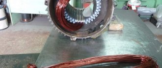
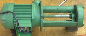
Its design contains a stator, a rotor (can be internal or external), brush-contact and bearing units, and a fan. All this is enclosed in a casing.
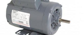
For your purposes, you can use different types of electric motors. These can be synchronous and asynchronous motors, single- and three-phase, BLDC type. They have different powers and are designed for different connection and operating conditions.
The electric motor must:
- Be able to develop significant torque starting from zero speed;
- Provide significant peak power to ensure trouble-free operation under extreme loads and power surges in the network;
- Have the simplest possible control system;
- Be light and compact;
- It is relatively inexpensive;
- They have high efficiency;
- Act as a generator when the vehicle slows down.
Therefore, an ideal motor should have excellent characteristics such as high starting torque, high power density and good energy efficiency.
To make the engine work, there are several connection schemes, the most common among them are star and delta.
Advantages and disadvantages
The advantages of such an electric motor include:
- high cosφ, approaching 1 in value, which is significantly superior to asynchronous electric motors;
- higher mechanical strength due to the design features of the electric motor;
- the dependence of torque on voltage is linear, not quadratic, so the oscillations of the electric motor are proportionally reduced;
- there is a constant speed on the electric motor shaft, independent of the applied load;
- can be used to reduce the reactive component in the network.
Among the disadvantages of synchronous electric motors are:
- complex design;
- more complex launch;
- the need to use auxiliary devices and blocks;
- such electric motors are more difficult to regulate in terms of speed;
- repairs and maintenance will also cost more than asynchronous electric motors.
Starting three-phase motors
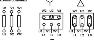
Star-delta starting is used on three-phase motors equipped with a terminal block with six terminals for the start and end of the winding, allowing both star and delta connections of the motor windings.
Triangle
A delta connection consists of connecting the end of the winding of a given phase to the beginning of the winding of the next phase. The windings connected in this way form a closed circuit and resemble a triangle in appearance.
Then the common points of the windings are connected to the next phases of the supply network. This connection does not use a neutral point at all. In a delta connection, each winding has a line-to-phase voltage, typically 400 V.
- When the motor windings are delta-connected, the current drawn by the motor from the mains is 3 times the current drawn in a star connection. In addition, the electromagnetic torque and therefore the motor power is three times higher in this case.
- Using a star-delta switch, we can start a star-connected motor, which will reduce the current draw from the mains, and then when the motor reaches the appropriate rotation speed, the stator windings need to be switched to delta so that the motor can provide the required power.
- In older solutions, switching was usually done manually by an operator; nowadays, special contactors and relay systems are used for this purpose, which switch automatically after a specified time.
The triangle connection of the motor windings must correspond to the rated voltage of the supply network. When the motor is powered from a three-phase network with a rated voltage of 400 V, the connection of the windings in a triangle corresponds to a voltage of 400 V, and when connected by a star, the supply voltage is reduced by the root of three. This means that when connected by a star, the voltage will be 1.7 times lower than the rated voltage of the supply network.
Star
A star connection is the connection of the ends of all three windings with one common point, and the remaining three ends with successive phases of the supply network.
Thus, each of the stator windings is connected at one end to the neutral wire (neutral), and at the other end to the phase wire.
Therefore, each of these windings has a phase voltage. It is not usually used to connect all windings to the neutral as this is not necessary.
- The starting torque of a three-phase star-connected motor is significantly less than that of direct starting, approximately 50% of the rated torque.
- Starting with a reduced supply voltage and therefore a reduced starting torque also causes a reduction in the starting current, which is usually in the range of 1.8 to 2.6 times the rated current depending on the type of motor and type of load.
- A significant limitation in the use of this method is the low starting torque, so this method can only be used when the mechanical load of the motor during starting is small, or the load is increasing at a higher speed close to the rated speed. speed.
- This load is typical for fans, pumps and centrifuges.
Selecting a connection diagram
If necessary, especially if you need to switch from 380V to 220V, the connection diagram can be changed. When the speed is close to the rated speed, the winding should be switched in a delta pattern.
- Switching the windings from star to delta too early will eliminate the benefits of this starting method.
- In this case, there will be a sharp jump in the current value to the characteristic value of the triangle. If the start time is correct, this move is minimal.
- The star-delta switch for higher power motors consists of three contactors and a time relay on which we set a time delay followed by delta switching and powering the motor with full mains voltage.
- This starting is only possible for 3-phase motors that have 6 terminals on the terminal block.
An electrical system with three terminals (in other words, "has three legs") is called a tee because this connection results in a system with three electrical terminals.
How to connect a single-phase asynchronous motor
Any asynchronous electric motor, designed for power from a single-phase 220 V network, has two windings - starting and working. A cylindrical aluminum blank is used as a “collector”, which is mounted on a shaft. You can even note that the cylinder on the rotor is, in fact, a short-circuited winding. There are many schemes for turning on an asynchronous motor, but few are used in practice:
- Using a ballast resistor connected to the start winding.
- With a capacitor on the start winding.
- Using a push-button or relay starter, a starting capacitor connected to the start winding circuit.
Very often, a combination of a push-button or relay starter, as well as a constantly switched on operating capacitor, is used. Instead of a relay, an electronic key based on a thyristor is very often used. Using this switch, a single-phase electric motor is connected with an additional group of capacitors.