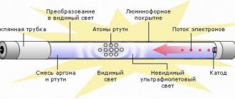
When the lamp is turned on, an electronic discharge occurs in the mercury vapor that fills the test tube and the resulting UV radiation affects the phosphor coating. Let's consider several options.
Tandem connection Below is a diagram where two fluorescent type lamps are connected in series. Connecting a fluorescent lamp Electronic ballast for two fluorescent lamps The advantages of electronic ballasts are described in the video. The simplest option is a self-oscillator converter circuit with 1 transistor.
To eliminate these shortcomings, electronic ballast control equipment circuits have been developed. After the time has elapsed, a high-voltage pulse is applied, which causes the discharge to ignite between the electrodes.
The switching circuit is designed in such a way that it has one choke for two light bulbs.
Perhaps one of the electrode threads has burned out. After which, due to the energy accumulated in the inductor, a voltage surge occurs and a glow discharge occurs in the lamp.
Scheme for switching fluorescent fluorescent lamps through an electromagnetic choke and starter.
The device of fluorescent lamps
In most light bulbs, the bulb is shaped like a cylinder. More complex geometric shapes are found. At the ends of the lamp there are electrodes, reminiscent in design of the spirals of incandescent light bulbs. The electrodes are made of tungsten and soldered to the pins located on the outside. Voltage is applied to these pins.
A gas environment is created inside the fluorescent lamp, which is characterized by negative resistance, which manifests itself when the voltage between the electrodes located opposite each other decreases.
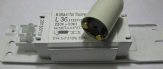
The lamp switching circuit uses a choke (ballast). Its task is to generate a significant voltage pulse, due to which the light bulb will turn on. The kit includes a starter, which is a glow discharge lamp with a pair of electrodes in an inert gas environment. One of the electrodes is a bimetallic plate. When turned off, the electrodes of the fluorescent light bulb are open.
The figure below shows a diagram of the operation of a fluorescent lamp.
How does a fluorescent lamp work?
The operating principles of fluorescent light sources are based on the following principles:
- Voltage is sent to the circuit. However, at first the current does not reach the light bulb due to the high voltage of the environment. The current moves through the spirals of the diodes, gradually heating them. The current is supplied to the starter, where the voltage is sufficient to produce a glow discharge.
- As a result of the heating of the starter contacts by the current, the bimetallic plate shorts. The metal takes on the functions of a conductor, and the discharge ends.
- The temperature in the bimetallic conductor drops, and the contact in the network opens. The inductor creates a high voltage pulse as a result of self-induction. As a result, the fluorescent light bulb lights up.
- A current flows through the lighting fixture, which is halved as the voltage across the inductor is reduced. It is not enough to start the starter again, the contacts of which are open when the light is on.
To create a circuit for switching on two light bulbs installed in one lighting fixture, you need a common choke. The lamps are connected in series, but each light source has a parallel starter.
Characteristics and markings
It is necessary to highlight several main characteristics of the device:
Life time. Phillips, for example, claims that its devices can withstand 6 thousand starts. Not far from him is Osram. But this is subject to normal voltage parameters in the network and many other factors.
Normal temperature. GOST provides the required temperature range from +5 to 55. If you need to use the lamp in other conditions, you will need to look for a special starter (there are such, but more expensive).
Cathode heating time. In other words, the duration of the period when the electrodes are closed
There is a large variation in this characteristic among manufacturers, so you need to pay attention to the recommendations of the manufacturer of the lighting part of the device.
Type of capacitor in the starter. Our manufacturer uses a foil product, which is a relic, but cheaper
The starter can operate without a capacitor (or with a failed one), however, the service life of the device will be reduced.
Rated voltage. By connecting a 127-volt starter to 220 volts, you can ruin the entire system in one moment.
Domestic markings are somewhat different from Western ones, but they can be combined into a single whole.
Our GOST:
- The big one is the starter.
- The numbers in front of it determine the lamp power (60, 90, 120).
- The numbers after indicate the voltage (127 and 220).
For example, 90C - 220. The marking states that the device is designed for a lamp with a power of 90 Watts and a voltage of 220 Volts.
Western marking:
- Lamps from 4 to 80 W with a voltage of 220 Volts - S10, FS-U, ST111.
- Voltage 127 and power up to 22 watts – S2, FS-2, ST151.
Connection options
Let's consider different options for connecting a fluorescent lamp.
Connection using electromagnetic balance (EMB)
The most common type of connection for a fluorescent light source is a circuit with a starter, where electronic ballasts are used. The principle of operation of the circuit is based on the fact that as a result of connecting the power, a discharge occurs in the starter and the bimetallic electrodes are short-circuited.
The current in the electrical circuit of the conductors and starter is limited only by the internal choke resistance. As a result, the operating current in the light bulb increases almost threefold, the electrodes rapidly heat up, and after the conductors lose temperature, self-induction occurs and the lamp ignites.
Disadvantages of the scheme:
- Compared to other methods, this is a rather expensive option in terms of energy consumption.
- Start-up takes at least 1 – 3 seconds (depending on the degree of wear of the light source).
- Inability to work at low air temperatures (for example, in an unheated basement or garage).
- There is a stroboscopic effect of flashing the light bulb. This factor negatively affects human vision. Such lighting cannot be used for production purposes, because fast moving objects (for example, a workpiece in a lathe) appear motionless.
- Unpleasant humming of the throttle plates. As the device wears out, the sound increases.
The switching circuit is designed in such a way that it has one choke for two light bulbs. The inductance of the inductor should be enough for both light sources. 127 volt starters are used. They are not suitable for a single-lamp circuit; 220 Volt devices are needed there.
The picture below shows a chokeless connection. The starter is missing. The circuit is used in case of burnout of filament lamps. A step-up transformer T1 and a capacitor C1 are used, which limits the current flowing through the light bulb from a 220-volt network.
The following circuit is used for light bulbs with burnt out filaments. However, there is no need for a step-up transformer, making the design of the device simpler.
Below is shown a method of using a diode rectifier bridge, which eliminates the flickering of a light bulb.
The figure below shows the same technique, but in a more complex design.
Two tubes and two chokes
To connect a fluorescent lamp, you can use a serial connection:
- The phase from the wiring is sent to the inductor input.
- From the inductor output, the phase goes to the contact of the light source (1). From the second contact it is sent to the starter (1).
- From the starter (1) it goes to the second contact pair of the same light bulb (1). The remaining contact is connected to zero (N).
Connect the second tube in the same way. First the inductor, then one contact of the light bulb (2). The second contact of the group is sent to the second starter. The starter output is combined with the second pair of light source contacts (2). The remaining contact should be connected to input zero.
Connection diagram for two lamps from one choke
The scheme provides for the presence of two starters and one choke. The most expensive element of the circuit is the inductor. A more economical option is a two-lamp lamp with a choke. The video explains how to implement the scheme.
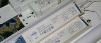
Electronic ballast
The disadvantages of the electronic ballast circuit necessitated the search for a more optimal connection method. During the research, a method involving electronic ballast was invented. In this case, it is not the mains frequency (50 Hz) that is used, but high frequencies (20 – 60 kHz). It is possible to get rid of the flashing light that is harmful to the eyes.
Externally, the electronic ballast is a block with terminals exposed to the outside. The inside of the device contains a printed circuit board on which the entire circuit can be assembled. The unit is small in size, thanks to which it fits into the housing of even a small lighting device. Switching on is much faster compared to the EMPA standard. The operation of the device does not cause acoustic discomfort. This connection method is called starterless.
It is not difficult to understand the principle of operation of a device of this type, since there is a diagram on its reverse side. It shows the number of lamps for connection and explanatory notes. There is information about the power of the light bulbs and other technical parameters of the device.
The connection is made as follows:
- The first and second contacts are connected to a pair of lamp contacts.
- The third and fourth contacts are directed to the remaining pair.
- Power is supplied to the input.
Using Voltage Multipliers
This option allows you to connect a fluorescent lamp without using an electromagnetic balance. Usually used to increase the service life of light bulbs. The connection diagram for burnt-out lamps makes it possible for the light sources to work for some more time, provided that their power is no more than 20 - 40 W. Filaments are allowed both suitable for work and burnt out. In any case, the thread leads must be short-circuited.
As a result of rectification, the voltage doubles, so the light bulb turns on almost instantly. Capacitors C1 and C2 are selected based on an operating voltage of 600 Volts. The disadvantage of capacitors is their large size. As capacitors C3 and C4, preference is given to mica devices rated at 1000 Volts.
Fluorescent lamps are not compatible with direct current. Very soon, so much mercury accumulates in the device that the light becomes noticeably weaker. To restore the brightness of the glow, change the polarity by turning the bulb over. Alternatively, you can install a switch so you don't have to remove the lamp every time.
Connection without starter
The method using a starter involves prolonged heating of the light bulb. In addition, this part must be changed frequently. A scheme where the electrodes are heated using old transformer windings allows you to do without a starter. The transformer acts as ballast.
Bulbs used without a starter must be marked RS (quick start). A light source started through a starter is not suitable, since its conductors take a long time to heat up and the spirals burn out quickly.
Serial connection of two light bulbs
In this case, it is necessary to connect two fluorescent lamps with one ballast. All devices are connected in series.
To carry out electrical work you will need the following parts:
- induction throttle;
- starters (2 units);
- fluorescent light bulbs.
The connection is made in the following order:
- We connect starters to each light bulb. The connection is made in parallel. The connection point is the pin input at the ends of the lighting device.
- We direct free contacts to the electrical network. We use a choke for connection.
- We connect capacitors to the contacts of the light source. They will allow you to reduce the intensity of interference in the network and compensate for power reactivity.
Note! In standard household switches (especially in inexpensive models), contacts often stick due to too high starting currents. In this regard, it is recommended to purchase high-quality switches for use in conjunction with fluorescent lamps.
Operating principle of electronic ballasts
Electronic ballasts (EPG) use the potential of modern power electronics and are more complex, but also more functional circuits. Such devices allow you to control the three startup phases and adjust the light output. The result is longer lamp life. Also, due to the lamp being powered with a current of a higher frequency (20÷100 kHz), there is no visible flicker. A simplified diagram of one of the popular electronic ballast topologies is shown in Fig. 2.
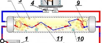
Rice. 2 Simplified circuit diagram of electronic ballasts In Fig. 2 D1-D4 – mains voltage rectifier, C – filter capacitor, T1-T4 – transistor bridge inverter with transformer Tr. Optionally, the electronic ballast may contain an input filter, a power factor correction circuit, additional resonant chokes and capacitors. A complete schematic diagram of one of the typical modern electronic ballasts is shown in Fig. 3.
Rice. 3 Circuit diagram of BIGLUZ electronic ballasts The circuit (Fig. 3) contains the main elements mentioned above: a bridge diode rectifier, a filter capacitor in the DC link (C4), an inverter in the form of two transistors with wiring (Q1, R5, R1) and (Q2, R2 , R3), inductor L1, transformer with three terminals TR1, trigger circuit and lamp resonant circuit. Two windings of the transformer are used to turn on transistors, the third winding is part of the resonant circuit of the LDS.
Replacing the lamp
If there is no light and the cause of the problem is only to replace a burnt out light bulb, proceed as follows:
- Let's disassemble the lamp. We do this carefully so as not to damage the device. Rotate the tube along its axis. The direction of movement is indicated on the holders in the form of arrows.
- When the tube is rotated 90 degrees, lower it down. The contacts should come out through the holes in the holders.
- The contacts of the new light bulb must be in a vertical plane and fit into the hole. When the lamp is installed, turn the tube in the opposite direction. All that remains is to turn on the power supply and check the system for functionality.
- The final step is the installation of a diffuser lamp.
System health check
After connecting the fluorescent lamp, you should make sure that it is working and that the ballasts are in good working order. To carry out the tests, you will need a tester with which to check the cathode filaments. The permissible resistance level is 10 ohms.
If the tester determines the resistance to be infinite, it is not necessary to throw away the light bulb. This light source still retains functionality, but it must be used in cold start mode. In the normal state, the starter contacts are open, and its capacitor does not allow direct current to pass through. In other words, the ringing should show a very high resistance, which sometimes reaches hundreds of ohms.
After touching the choke terminals with the ohmmeter probes, the resistance gradually decreases to a constant value inherent in the winding (several tens of Ohms).
Note! The faulty state of the throttle is indicated by the burnout of a recently installed light bulb.
It is not possible to reliably determine the turn-to-turn short circuit in the inductor winding using a conventional ohmmeter. However, if the device has an inductance measurement function and data on electronic ballasts, a discrepancy between the values will indicate a problem.
Working with the chuck
Lamp sockets can be installed in different ways: horizontally or vertically, in some models at an angle
Since fluorescent lamps illuminate 360 degrees, it does not matter how they are installed in the socket
The luminous flux of LED lamps is directional, so here it is necessary to pay attention to the placement of the slot in the socket. It may happen that the luminous flux of the connected lamps will be directed not downwards, but to the side
In this case, the most universal are rotary type bases. They are suitable for any model of lamps and allow you to adjust the direction of light.
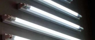
Fluorescent lamps, thanks to their revolutionary characteristics for their time: low energy consumption, high luminous efficiency and long service life, became very widespread.
It is tubular fluorescent lamps that illuminate most schools, hospitals, offices, workshops, etc.; most often they are installed in raster lamps, familiar to everyone.
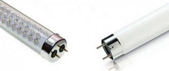
The main disadvantage of fluorescent lamps is the presence of mercury inside them, the vapors of which are deadly to humans.
But technology does not stand still; its active development has led to the creation of LED lamps, which have surpassed fluorescent lamps in almost all respects. Currently, their only drawback is the cost in comparison with fluorescent lamps, but in terms of the sum of all the characteristics and benefits, and most importantly for safety reasons, they are unrivaled.
It is not profitable to replace old fluorescent lamps entirely with similar LED lamps, at least simply economically; it is better to simply replace the lamps, because manufacturers have long been producing T8 tubular LED lamps for the G13 base and you can install them, leaving the old lamp body, only slightly modernizing it.
To install LED lamps instead of fluorescent ones, it is necessary to slightly modify the lamp, make it simpler, and remove several unnecessary components from the connection diagram. Now I will show in detail how easy it is to do it yourself.
First of all, let's look at the diagrams of standard raster lamps, designed to install four fluorescent lamps, these are most often mounted in Armstrong-type ceilings.
There are only two varieties of them, two different schemes, the first with ballast and starter, is the most common:
The second scheme is more modern, with an electronic ballast:
As you can see, lamps with fluorescent lamps contain various additional equipment inside that is required for their operation. Read more about this in the material – Connection diagram for fluorescent lamps
In modern tubular LED lamps, in particular T8 with g13 socket, the driver necessary for the LEDs to light is already built into the body of the lamp itself and there is no need to install anything additional.
Accordingly, remodeling any fluorescent lamp comes down to dismantling all unnecessary equipment: ballast, starter, electronics, etc. and connecting power directly to the contacts of the LED lamp. For both types of lamps, the connection diagram is common, all green conductors in the diagram are connected to the neutral wire, and all red ones to the phase wire, it should turn out something like this: