Soft starter for electric motors
Soft starting of an electric motor has recently been used more and more often. Its applications are varied and numerous. These are industry, electric transport, utilities and agriculture. The use of such devices can significantly reduce starting loads on the electric motor and actuators, thereby extending their service life.
Starting currents
Starting currents reach values 7... 10 times higher than in operating mode. This leads to a “lower” voltage in the electrical network, which negatively affects not only the operation of other consumers, but also the engine itself. The start-up time is delayed, which can lead to overheating of the windings and gradual destruction of their insulation. This contributes to premature engine failure.
Soft starters can significantly reduce the starting load on the electric motor and the electrical network, which is especially important in rural areas or when the engine is driven by an autonomous power plant.
Overload of actuators
When the engine starts, the torque on its shaft is very unstable and exceeds the rated value by more than five times. Consequently, the starting loads of the drives also increase compared to full operation and can reach 500 percent. Instability of the starting torque leads to shock loads on the gear teeth, shearing of keys, and sometimes even to twisting of the shafts.
Devices for soft starting of an electric motor significantly reduce starting loads on the mechanism - the gaps between the gear teeth are selected evenly, which prevents their breakdown. In belt drives, the drive belts are also tensioned evenly, which reduces wear on the mechanisms.
In addition to a smooth start, the soft braking mode has a beneficial effect on the operation of mechanisms. If the engine drives the pump, gentle braking prevents water hammer when the unit is switched off.
Industrial soft starters
Soft starters are currently produced by many companies, for example, Siemens, Danfoss, Schneider Electric. These devices have many user programmable features. These are acceleration time, deceleration time, overload protection and many other additional functions.
Despite all the advantages, branded devices have one drawback - a rather high price. However, you can make such a device yourself. At the same time, its cost will be small.
Soft start device based on KR1182PM1 microcircuit
The first part of the article talked about the specialized KR1182PM1 microcircuit, which is a phase power stabilizer. Typical circuits for its ignition, soft start devices for incandescent lamps and simply power regulators in the load are considered. Based on this microcircuit, you can make a fairly simple soft starter for a three-phase electric motor. The device diagram is shown in Figure 1.
Figure 1. Scheme of the motor soft start device.
Soft starting is carried out by gradually increasing the voltage on the motor windings from zero to nominal. This is achieved by increasing the opening angle of the thyristor switches over a period of time called the start time.
Description of the scheme
The design uses a three-phase electric motor 50 Hz, 380 V. The star-connected motor windings are connected to the output circuits indicated in the diagram as L1, L2, L3. The midpoint of the star is connected to the neutral (N).
The output switches are made using thyristors connected back-to-back in parallel. The design uses imported 40TPS12 type thyristors. At a low cost, they have a fairly high current - up to 35 A, and their reverse voltage is 1200 V. In addition to them, the keys have many other elements. Their purpose is as follows: RC damping circuits connected in parallel with the thyristors prevent false ignition of the latter (in the diagram these are R8C11, R9C12, R10C13) and with the help of varistors RU1 ... RU3 switching noise is absorbed, the amplitude of which exceeds 500 V.
DA1...DA3 microcircuits of type KR1182PM1 are used as a control unit for output keys. These microcircuits were discussed in some detail in the first part of the article. Capacitors C5...C10 inside the microcircuit form a sawtooth voltage, which is synchronized with the mains voltage. The control signals of the thyristor in the microcircuit are formed by comparing the sawtooth voltage with the voltage between pins 3 and 6 of the microcircuit.
To power relays K1...K3, the device has a power supply, which consists of only a few elements. This is transformer T1, bridge rectifier VD1, smoothing capacitor C4. An integrated stabilizer DA4 type 7812 is installed at the rectifier output, providing an output voltage of 12 V and protection against short circuits and output overloads.
Description of the operation of the soft starter for electric motors
When switch Q1 is closed, line voltage is applied to the circuit. However, the engine has not started yet. This is due to the fact that the windings of relay K1... K3 are still de-energized, and their normally closed contacts bypass contacts 3 and 6 of microcircuits DA1... DA3 through resistors R1... R3. This circumstance does not allow charging capacitors C1 ... C3, so the microcircuit does not generate control pulses.
Putting the device into operation
When toggle switch SA1 is closed, the 12 V voltage turns on relay K1... K3. Their normally closed contacts are open, which makes it possible to charge capacitors C1 ... C3 from internal power sources. Along with the increase in voltage across these capacitors, the opening angle of the thyristors increases. In this way, a gradual increase in voltage is achieved on the motor windings. When the capacitors are fully charged, the switching angle of the thyristors will reach the maximum value and the motor speed will reach the rated speed.
Stopping the engine, smooth braking
To stop the engine, open switch SA1, this will turn off relay K1... K3. Their normally closed contacts will close, which will lead to the discharge of capacitors C1... C3 through resistors R1... R3. The discharge of the capacitors will last for several seconds, and the engine will stop.
When starting the engine, significant currents can flow in the neutral wire. This is due to the fact that during the process of gradual acceleration, the currents in the motor windings are not sinusoidal, but you should not be particularly afraid of them - the starting process is quite short. In stationary mode, this current will be significantly lower (no more than ten percent of the phase current in nominal mode), which is associated only with the technological variation in winding parameters and “imbalance” of the phases. It is no longer possible to get rid of these phenomena.
Details and design
To assemble the device you will need the following parts:
Transformer with a power of no more than 15 W, with an output winding voltage of 15... 17 V.
Any coil voltage of 12 V, with a normally closed or switching contact, for example TRU-12VDC-SB-SL, is suitable as relay K1 ... K3.
Capacitors C11...C13 type K73-17 for an operating voltage of at least 600 V.
The device is made on a printed circuit board. The assembled device must be placed in a plastic container of a suitable size, on the front panel of which the switch SA1 and LEDs HL1 and HL2 should be located.
Motor connection
The connection between switch Q1 and the motor is carried out with wires whose cross-section corresponds to the power of the latter. The neutral wire is made of the same wire as the phase wires. With the power of the components indicated in the diagram, you can connect motors with a power of up to four kilowatts.
If it is intended to use a motor with a power of no more than one and a half kilowatts, and the start-up frequency will not exceed 10... 15 per hour, then the power dissipated by the thyristor switches is insignificant, then radiators can not be installed.
If you plan to use a more powerful motor or it starts more often, you will need to install thyristors on aluminum strip radiators. If the radiator is to be shared, the thyristors should be isolated from it using mica spacers. To improve cooling conditions, you can use heat-conducting paste KPT-8.
Device control and configuration
Before switching on, first make sure that the installation matches the electrical diagram. This is a basic rule that cannot be deviated from. After all, neglecting this control can lead to charring of many parts and discourage the desire to “experiment with electricity” for a long time. Detected errors must be eliminated, because this circuit is powered from the network, and it’s bad to joke with it. And even after this check it is still too early to connect the motor.
First, instead of the engine, connect three identical incandescent lamps with a power of 60 ... 100 W. During testing, it is necessary to ensure that the lamps “light up” evenly.
The uneven ignition time is due to changes in the capacitances of capacitors C1... C3, which have a significant tolerance on capacitance. Therefore, it is best to collect them immediately before installation using the device, at least with an accuracy of ten percent.
The shutdown time is also related to the resistance of resistors R1... R3. With their help you can equalize the shutdown time. These adjustments must be made if the distance between the on and off times in different phases exceeds 30 percent.
The motor can only be connected after the above checks are normal, not even perfect.
What else can you add to your design?
It has already been said above that similar devices are currently produced by several companies. Of course, it is impossible to replicate all the functions of branded devices in such a homemade device, but it will probably be possible to copy it.
This is the so-called bypass contactor. Its purpose is this: after the motor has reached its rated speed, the contactor simply connects the thyristor switches with its contacts. Current flows through them, bypassing the thyristors. This design is often called a bypass (from the English Bypass). For this improvement it will be necessary to introduce additional elements into the control unit.
Electric motors are widely used in all spheres of human activity. However, when starting the electric motor, a sevenfold current consumption occurs, causing not only an overload of the electrical network, but also heating of the stator windings, as well as failure of mechanical parts. To eliminate this undesirable effect, radio amateurs are recommended to use soft starters for the electric motor.
Smooth engine start
The stator of an electric motor is an inductor, so there are active and reactive components of resistance (R). The value of the reactive component depends on the frequency characteristics of the power source and at startup changes from 0 to the calculated value (when the device is running). The current, called inrush current, also changes.
The starting current is 7 times the rated value. At the same time, the windings of the stator coil heat up, and if the wire making up the winding is old, a short circuit between the turns is possible (as the value of R decreases, the current reaches its maximum value). Overheating will shorten the tool life. To avoid this problem, there are several options for using soft starters.
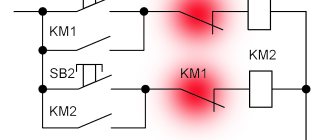
By switching the windings, the motor soft starter (SCP) consists of the following main blocks: 2 types of relay (on time and load control), three contactors (Figure 1).
Figure 1 - General diagram of the soft start device for asynchronous motors (soft start).
Figure 1 shows an induction motor. Its windings are connected by a star. Starting occurs with contactors K1 and K3 closed. After a certain time interval (set by a time relay), contactor K3 opens its contact (opening occurs) and is activated by contact K2. The circuit in Figure 1 is applicable to various types of soft starter motors.
The main disadvantage is the formation of short circuit currents when 2 circuit breakers are turned on simultaneously. This problem is eliminated by introducing a switch into the circuit instead of contactors. However, the stator windings continue to heat up.
When electronically controlling the starting frequency of an electric motor, the principle of frequency variation of the supply voltage is used. The main element of these converters is the frequency converter, which includes:
- The rectifier is installed on powerful semiconductor diodes (a thyristor version is possible). It converts the mains voltage value into pulsating direct current.
- The intermediate circuit reduces noise and ripple.
- an inverter is needed to convert the signal received at the output of the intermediate circuit into a signal with varying amplitude-frequency characteristics.
- The electronic control circuit generates signals for all components of the converter.
Principle of operation, types and choice
With a 7-fold increase in rotor torque and IP, to extend service life, it is necessary to use a soft starter that meets the following requirements:
- Uniform and regular increase in all indicators.
- Electrical control of braking and engine starting at specified intervals.
- Protection against voltage surges, loss of any phase (for a three-phase electric motor) and various types of interference.
- Increased wear resistance.
The principle of operation of a triac soft start device: limiting the voltage value by changing the opening angle of the semiconductors of the triac (triac) when connected to the stator windings of the electric motor (Figure 2).
Figure 2 - Scheme of soft start of an electric motor using a triac.
Thanks to the use of triacs, it becomes possible to reduce the starting currents by 2 or more times, and the presence of a contactor allows you to avoid overheating of the triacs (in Figure 2: Bypass). The main disadvantages of triac soft starters:
- The use of simple circuits is possible only at low loads or starting without load. Otherwise, the scheme becomes more complicated.
- During a long start-up, overheating of the windings and semiconductor devices occurs.
- The engine sometimes does not start (leading to significant overheating of the windings).
- Overheating of the windings is possible during electrical braking of the electric motor.
Soft starters with open-loop regulators (single- or three-phase) are widely used. In models of this type, it is necessary to set the motor starting time and voltage immediately before starting. The disadvantage of the devices is the inability to adjust the torque of moving mechanical parts depending on the load. To eliminate this problem, it is necessary to use a device to reduce Ip, protection against various phase shifts (occurs when phases are unbalanced) and mechanical overloads.
More expensive models of soft starters provide the ability to monitor motor parameters in continuous mode.
For devices containing electric motors, a triac starter is provided. They differ in the circuit and method of regulating the mains voltage. The simplest circuits are those with single-phase regulation. They are made on a triac and can reduce the load on the mechanical part; they are used for electric motors with a power of less than 12 kV. Enterprises use three-phase voltage regulation for electric motors with power up to 260 kW. When choosing the type of soft starter, you must be guided by the following parameters:
- Device power.
- Work mode.
- Equality between the IP of the motor and the soft starter.
- The number of throws at any given time.
To protect the pumps, soft starters are suitable that protect against shock from the hydraulic component of the hose (Advanced Control). Soft starters for tools are selected depending on loads and high speeds. Expensive models have such protection in the form of a soft starter, while inexpensive ones require you to do it yourself. It is used in chemistry laboratories to smoothly start the coolant fan.
Reasons for using the grinder
Due to the design features, when starting an angle grinder, high dynamic loads occur on the tool parts. During the initial rotation of the disk, inertial forces act on the gear axis:
- The impact of inertia can tear the grinder out of your hands. There is a threat to life and health, as this product is very dangerous and requires strict adherence to safety precautions.
- When starting, an overcurrent occurs (Istart = 7 * Inom). Premature wear of the brushes and overheating of the windings occur.
- The gearbox is worn out.
- Destruction of the cutting disc.
An instrument that is not tuned becomes very dangerous, as there is a possibility of harm to health and life. Therefore, it is necessary to protect it. For this purpose, the control unit for power tools is assembled with your own hands.
DIY creation
For inexpensive models of angle grinders and other tools, you need to assemble your own soft starter. This is not difficult to do, because thanks to the Internet you can find a huge number of schemes. The simplest and at the same time the most effective is a universal soft-start circuit based on a triac and a microcircuit.
When you turn on an angle grinder or other tool, the windings are damaged and the tool is changed due to a rough start. Radio amateurs found a way out of this situation and proposed a simple smooth start of a power tool with their own hands (diagram 1), assembled in a separate unit (there is very little space in the case).
Scheme 1 - Scheme for soft start of a power tool.
The do-it-yourself soft starter is based on KR118PM1 (phase control) and a triac power supply. The strength of the device is its versatility, because it can be connected to any power tool. Not only is it easy to install, it doesn't even require any prior setup. In principle, connecting the system to the device is simple and is installed in the break of the power cable.
Features of the soft starter module
When the grinder is turned on, voltage is applied to KR118PM1, and as charge accumulates on the control capacitor (C2), the voltage gradually increases. The thyristors in the microcircuit open gradually with some delay. The triac opens with a pause equal to the thyristor delay. For each subsequent voltage period, the delay gradually decreases and the device starts smoothly.
The ramp-up time depends on the capacitance C2 (at 47 µm the ramp-up time is 2 seconds). This delay is optimal, although it can be changed by increasing the capacitance of C2. After turning off the angle grinder (angle grinder), capacitor C2 is discharged due to resistance R1 (discharge time approximately 3 seconds at 68 kOhm).
This motor speed control circuit can be upgraded by replacing R1 with a variable resistor. When the resistance value of the variable resistor changes, the power of the electric motor changes. Resistor R2 performs the function of regulating the amplitude of the current flowing through the input of triac VS1 (it is advisable to provide cooling with a fan), which is the control one. Capacitors C1 and C3 serve to protect and control the microcircuit.
The triac is selected with the following characteristics: the maximum forward voltage is up to 400-500 V, and the minimum transmission current through the transitions must be at least 25 A. When manufacturing a soft starter according to this scheme, the power reserve can vary from 2 kW to 5 kW.
Therefore, to increase the life of tools and motors, it is necessary to run them smoothly. This is due to the design feature of asynchronous electric motors and commutators. When starting, current is quickly consumed, resulting in wear and tear on electrical and mechanical parts. Using a soft starter allows you to make your power tool safe by following safety regulations. When upgrading a tool, you can buy ready-made models and assemble a simple and reliable universal device that is not only different, but superior to some factory soft starters.
Soft starting is widely used for safe starting of electric motors. When starting the engine, the rated current (In) is exceeded by 7 times. As a result of this process, there is a reduction in the operating period of the engine, namely the stator windings and a significant load on the bearings. It is for this reason that it is recommended to soft-start a power tool with your own hands where it is not intended.
Voltage waveforms
The nut of knowledge is hard, but still we are not used to retreating! The newsreel “I Want to Know Everything!” will help us split it.
Anyone can assemble a circuit with a screwdriver. And for those who want to see the voltage and understand what real processes are taking place, they cannot do without an oscilloscope. I am publishing oscillograms at the 2T1 output of the soft starter.
The engine is turned off. Pure sine.
Isn't it a logical inconsistency - the engine is turned off, but there is voltage on it?! This is a feature of some soft starters. Unpleasant and dangerous. Yes, there is 220V voltage on the engine, even when it is stopped.
The fact is that control occurs only in two phases, and the third (L3 - T3) is connected directly to the motor. And since there is no current, all outputs of the device are affected by phase L3 voltage, which passes through the motor windings. The same nonsense happens in three-phase solid-state relays, here is my article.
Be careful! When servicing a motor connected to a soft starter, turn off the input circuit breakers and check that there is no voltage!
Launch. Thyristors cut the phase mercilessly.
Since the load is inductive, the sine wave is not only cut into pieces, but also greatly distorted.
There is interference, and this must be taken into account - malfunctions in the operation of controllers and other low-current devices are possible. To reduce this influence, it is necessary to space and shield the circuits, install chokes at the input, etc.
The engine is almost on. About 90% of sine energy.
The photo was taken a couple of seconds before the internal contactor (bypass) turned on, which supplied full voltage to the motor.
General information
The stator of an electric motor is an inductor, so there are resistors with active and reactive components.
When electric current flows through radioelements that have resistance with an active component, losses occur due to the conversion of part of the power into the thermal form of energy. For example, the resistor and stator winding of an electric motor have a resistor with an active component. It is not difficult to calculate active resistance, since the phases of the current (I) and voltage (U) coincide. Using Ohm's Law for a section of circuit, you can calculate the resistance: R = U / I. It depends on the material, cross-sectional area, length and temperature.
If the current passes through reactive type elements (with capacitive and inductive characteristics), then in this case a reactive R appears. An inductor has practically no active resistance (the calculations do not take into account the R of its windings.). This type of R is created due to the self-acting electromotive force (EMF), which is directly proportional to the inductance and frequency I passing through its turns: Xl = wL, where w is the angular frequency of the alternating current (w = 2 * Pi * f, ef is the frequency network) and L - inductance (L = n * n / Rm, n - number of turns and Rm - magnetic resistance).
When the electric motor is turned on, the starting current is 7 times higher than the rated current (the current consumed when the tool is running), and the stator windings heat up. If the stator winding is old, a short circuit may occur between the turns, causing damage to the power tool. To do this, you need to use a soft starter for a power tool.
One way to reduce the inrush current (Ip) is to switch windings. Its implementation requires 2 types of relays (time and load) and the presence of three contactors.
Starting an electric motor with star-connected windings is only possible if 2 contactors are not closed at the same time. After a certain time interval set by the time relay, one of the contactors is turned off, and the other, not previously activated, is turned on. Thanks to this alternation of ignition of the windings, the starting current is reduced. This method has a significant drawback, since when two contactors are closed simultaneously, a short circuit current occurs. However, when using this method, the windings continue to heat up.
Another way to reduce the starting current is to adjust the starting frequency of the motor. The principle of this approach is to change the frequency of the power source U. The main element of a soft starter of this type is a frequency converter, consisting of the following elements:
- Rectifier.
- Intermediate chain.
- Inverter.
- Electronic control circuit.
The rectifier consists of powerful diodes or thyristors, which serve as a converter of U mains power into a direct pulsating current. The intermediate circuit attenuates the pulsating direct current at the output of the rectifier, which is collected on large capacitors. An inverter is needed to directly convert the signal at the output of the intermediate circuit into an amplitude-frequency signal of an alternating component. An electronic control circuit is necessary to generate the signals necessary to control the rectifier, inverter.
Operating principle
When starting a commutator-type electric motor, a significant short-term increase in current consumption occurs, which causes premature failure of the power tool and requires it to be sent for repair. Electrical parts wear out (the current is 7 times higher) and mechanical parts (sharp start). To organize a “soft” start, it is necessary to use a soft start device (hereinafter referred to as the soft start device). These devices must meet the basic requirements:
- Gradual increase in load.
- Ability to start the engine at regular intervals.
- Provides protection against linear overvoltages U, phase loss (for a three-phase electric motor) and various electrical noise.
- Significantly increased service life.
The most popular are triac soft starters, the operating principle of which is to smoothly adjust U by adjusting the opening angle of the triac junction. The triac must be connected directly to the motor windings, which allows reducing the starting current by 2–5 times (depending on the triac and control circuit). The main disadvantages of triac soft starters:
- Complex schemes.
- Overheating of windings during long starts.
- Problems with starting the engine (leads to noticeable heating of the stator windings).
The circuits become more complicated when using powerful engines, but at low loads and idle speed, simple circuits can be used.
Soft starters with open loop controllers (1 or 3 phase) are widely used. In models of this type, it becomes possible to pre-set the start time and U value before starting the engine. However, in this case it is impossible to regulate the amount of torque under load. This model uses a special device to reduce inrush current, protect against losses and phase imbalance, as well as overload. Factory models have a function for monitoring the condition of the electric motor.
The simplest single-phase control circuits are made using a triac and are used for instruments with a power of up to 12 kW. There are more complex schemes that allow you to adjust the power parameters of an engine with a power of up to 260 kW. When choosing a factory-made soft starter, the following parameters must be taken into account: power, possible operating modes, equality of permissible currents and the number of starts in a given period of time.
Are motors and loads a problem?
The fact is that virtually any electric motor, at the moment of starting or stopping the rotor, experiences enormous loads. The more powerful the engine and the equipment it drives, the greater the costs of starting it.
Probably the most significant load placed on the engine at the time of start-up is a multiple, albeit short-term, excess of the rated operating current of the unit. After just a few seconds of operation, when the electric motor reaches its normal speed, the current consumed by it will also return to normal levels. To ensure the necessary power supply, it is necessary to increase the capacity of electrical equipment and conductive lines , which leads to their rise in price.
When starting a powerful electric motor, due to its high consumption, the supply voltage “drops”, which can lead to failures or failure of equipment powered from the same line. In addition, the service life of power supply equipment is reduced.
If emergency situations occur that result in engine burnout or severe overheating, the properties of transformer steel can change so much that after repair the engine will lose up to thirty percent of its power. Under such circumstances, it is no longer suitable for further use and requires replacement, which is also not cheap.
Application in an angle grinder
When starting up an angle grinder (angle grinder), high dynamic loads are placed on the tool parts.
UPPs are equipped with expensive models, but not with ordinary varieties, for example, angle grinders from Interskol. An inertial shot can tear the grinder out of your hands, which poses a threat to life and health. In addition, when starting the electric motor of the tool, an overcurrent occurs and, as a result, wear of the brushes and significant heating of the stator windings, the gearbox wears out and the cutting disc can break, which can break at any time and cause harm to health, and possibly even life. The tool must be protected and for this you should make your own grinder with speed control and soft start.
Commutator motor speed controller
Most circuits for household appliances and electrical tools are based on a 220 V commutator motor. This demand is explained by its versatility. The units can be powered from direct or alternating voltage. The advantage of the circuit is due to the provision of effective starting torque.
To achieve a smoother start and have the ability to adjust the rotation speed, speed controllers are used.
You can start an electric motor with your own hands, for example, in this way.
Homemade options
There are many schemes for upgrading power tools with a soft starter. Of all the varieties, devices based on triacs are widely used. A triac is a semiconductor element that allows you to easily adjust power parameters. There are simple and complex circuits that differ from each other in design options, as well as in the supported power of the connected power tool. The design has internal ones, which allow cutting into the body, and external ones, made in the form of a separate module, which acts as a speed limiter and starting current when directly starting the angle grinder.
The simplest scheme
The soft starter with a thyristor speed controller KU 202 has found wide application due to its very simple design diagram (scheme 1). Connecting it does not require any special skills. It is very easy to purchase radioelements for it. This regulator model consists of a diode bridge, a variable resistor (plays the role of a U regulator) and a thyristor tuning circuit (supplying U to a control output with a nominal value of 6.3 volts) from a domestic manufacturer.
Scheme 1. Connection diagram of the indoor unit with speed control and soft start (connection diagram)
Due to the size and number of parts, this type of regulator can be built into the body of a power tool. In addition, the variable resistor knob should be removed, and the speed controller itself can be changed by inserting a button in front of the diode bridge.
The basic principle of operation is to regulate the rotation speed of the tool's electric motor by limiting power manually. This circuit allows the use of power tools up to 1.5 kW. To increase this indicator, it is necessary to replace the thyristor with a more powerful one (information about this can be found on the Internet or in a reference book). In addition, it must be taken into account that the thyristor control circuit will differ from the original one. KU 202 is an excellent thyristor, but its significant drawback is its adjustment (selection of parts for the control circuit). To implement a soft start in automatic mode, circuit 2 is used (soft starter on a microcircuit).
Soft start on a chip
The optimal option for manufacturing a soft starter is a soft starter circuit based on a triac and a microcircuit that controls the smooth opening of a pn-type junction. The device is powered by a 220 V network and is easy to assemble with your own hands. A very simple and universal soft start circuit for an electric motor also allows you to adjust the speed (diagram 2). The triac can be replaced with a similar one or with superior characteristics compared to the original, according to the reference book of semiconductor-type radioelements.
Diagram 2. Scheme of gradual start-up of a power tool
The device is implemented on the basis of the KR118PM1 microcircuit and a triac. Due to the versatility of the device, it can be used with any tool. Does not require configuration and is installed into the power cable break.
When the electric motor starts, U is supplied to KR118PM1 and the charge of capacitor C2 gradually increases. The thyristor opens gradually with a delay, which depends on the capacitance of the control capacitor C2. With a capacitance C2 = 47 µF, the start delay is about 2 seconds. This directly depends on the capacitance of the capacitor (with a larger capacitance, the start-up time increases). When the angle grinder is turned off, capacitor C2 is discharged by resistor R2, whose resistance is 68 kOhm, and the discharge time is approximately 4 seconds.
To control the speed, you need to replace R1 with a variable resistor. When changing the variable resistor parameter, the power of the electric motor changes. R2 changes the amount of current flowing through the input of the triac. The triac needs cooling, so a fan can be built into the module housing.
The main function of capacitors C1 and C3 is protection and control of the microcircuit. The triac should be selected based on the following characteristics: direct U should be 400..500 V, and direct current should be at least 25 A. With such ratings of radio elements, it is possible to connect a device with power from 2 kW to 5 kW to a soft starter.
Therefore, to start the electric motors of various tools, you need to use a factory-made or home-made soft starter. Soft starters are used to increase tool life. When starting the engine, there is a sharp increase in power consumption by 7 times. For this reason, it is possible to burn the stator windings and wear out the mechanical part. Soft starters can significantly reduce the starting current. When manufacturing a soft starter, you must follow safety rules when working with electricity.