How to determine phase, zero and grounding yourself, using improvised means?
Anyone doing electrical work at home or simply deciding to install a chandelier, sconce, or connect an outlet will definitely be faced with the question - how to determine the phase, neutral and grounding of the wires at the installation site?
In our articles and instructions, we often post connection diagrams, rules for installing and connecting electrical equipment to the network, as well as much more, where in order to correctly perform all operations you need to know where your phase wire is, where the neutral (working zero) is, and where the ground wire is (protective zero). For an experienced electrician, determining where the phase and zero are or finding the ground is usually not difficult, but what about the rest?
Let's try to figure out how at home, without having complex specialized measuring instruments and electronic devices, you can determine for yourself where the phase is, where the zero is, and where the ground is in the wiring.
Of all the known methods, the simplest determination of phase and zero, we have selected the most, in our opinion, accessible to implementation and at the same time safe. For this reason, in the article you will not see advice on how to find the phase using potatoes or calls for briefly touching the wires with various parts of the body.
How to connect a plug - with grounding
Another article in the “ELECTRICAL” section - I propose to talk about connecting an electrical plug to a regular cable, we will consider the option with grounding, because I personally think this option is the only correct one to use. Where do we need such knowledge? Typically, large electrical appliances are supplied without plugs - such as water heaters, some household appliances (ovens), and some lighting fixtures. In general, you need to know how it connects, and it’s quite simple...
CONTENTS OF THE ARTICLE
About power
First, guys, let's talk about maximum power.
Why am I starting this conversation? It’s simple - many people try to connect a plug to an induction hob! Guys, this can be dangerous - the surface consumes about 7 kW and not all plugs can withstand it, especially if you have a regular 16A plug, for “induction” you need a 40A plug or a direct connection - read this article , a regular one will simply melt from such a load !
This simple example shows us that first you need to estimate the power of your electrical appliance. If there is an oven, then the consumption is about 2.8 kW, if the water heater (I mean the storage type) - there is 1.5 - 2. KW, a 16A plug is enough for them. In general, the maximum voltage should be written on the packaging, here is a photo.
What tools will you need?
You need to take a screwdriver, preferably a Phillips screwdriver.
A knife (can be a plastic penknife) to cut and strip the cable.
Now the process itself.
We bought the required option, we also have a 3 X 2.5 mm cable, flat (this is what we will connect).
We unscrew the case, usually it is held on by one bolt, either on the side (like mine) or from the bottom.
We see a contact group - “phase” and “zero” are connected to the main fastenings, the contact in the middle is grounding.
Now we strip the cable. We need to achieve three separate wires with stripped wires at the end, about 1 cm, no more is needed. Let's look at the photo.
Now we connect the blue and brown wires (there may be variations - red and blue) to the main contacts.
The remaining yellow (sometimes green-yellow or white) is connected to a grounded connector.
All contacts need to be stretched well so that the wires sit well.
After that, we put everything into the case and assemble it. Then tighten it with a bolt.
That's it, the fork is assembled. As you can see, nothing complicated.
Now video version
VIDEO
I’ll finish here, read our construction site.
remo-blog.ru
Wire marking by color
Indeed, the easiest way to determine the phase, neutral and ground of an electrical wire is to look at the color marking and compare it with the accepted standard. Each core in modern wires used in electrical wiring and electrical equipment has an individual color. Knowing which color of cores corresponds to which function (phase, neutral or grounding), you can easily carry out further installation.
Quite often, this is quite sufficient, especially in cases where the installation is carried out in new buildings or places with fairly new electrical wiring, made by professional, competent electricians in accordance with all modern rules and standards.
According to this standard for residential electrical networks:
Working zero (neutral or zero) - Blue wire or blue-white
Protective zero (earth or grounding) - yellow-green wire
Phase – All other colors including black, white, brown, red, etc.
Now, knowing the standard for color marking of wires, you can easily determine which wire performs which function. This applies to most cases, the exception may be wires suitable for switches, switches, etc., due to the fundamentally different operating scheme of this electrical equipment.
Socket connection diagram
Greetings, dear readers of the site https://elektrik-sam.info.
In this article we will take a detailed look at how to properly connect an outlet and various connection diagrams.
The socket is used to connect electrical appliances to the electrical network and generally has two contacts in the form of a socket connector and spring grounding contacts.
The phase wire L (red) and the zero working wire N (blue) are connected to the power contacts of the socket; the protective PE conductor (yellow-green) is connected to the spring contact.
Let's look at the diagram for connecting sockets in residential buildings.
From the electrical panel, phase (red), zero (blue) and ground (yellow-green) from the circuit breaker of the socket group are supplied to the branch box via a three-wire cable.
In the branch box, the cable from the electrical panel branches - one goes to the outlet, and the other goes to another branch box, for connecting other outlets. The last socket in the group (socket 3 in the figure) is connected in the same box as socket 2. That is You don't need a separate box for it.
In branch boxes, wires of the same name are connected color to color: phase to phase, zero to zero, ground to ground. The connection points in the figure are shown with bold dots.
In the case of two-wire electrical wiring without a third separate ground wire, the so-called “two-wire”, which is found in older houses, the wiring diagram for the outlets will look the same, only the third yellow-green wire will be missing.
In this case, the sockets themselves must be used without a grounding contact.
Currently, a large number of household appliances and electrical appliances are used, and for ease of connection, instead of one separately installed socket, socket blocks with two, three or more sockets are used.
How to properly connect the outlet in this case? One of the outlets is connected to the wire coming from the junction box, and the rest are connected to the first outlet of this outlet block through screw terminals.
The figure above shows a diagram of connecting socket blocks in the electrical wiring of an apartment.
The socket block is installed in a common frame, which comes in two, three, four and five sockets.
In two-wire wiring, a separate ground wire is not used, and the socket connection diagram will look like the figure below.
Thus, we have considered the basic diagrams of how to properly connect sockets.
I recommend watching the video How to connect sockets:
Useful
HOW TO DETERMINE PHASE, ZERO and GROUNDING OF WIRES YOURSELF
So, let's start in order:
PHASE DETERMINATION
For greater convenience, it is always better to first determine which of the existing wires is phase. We have already written about how to find the phase with a digital multimeter, but what to do if you don’t have one, read below.
PHASE DETERMINATION WITH AN INDICATOR SCREWDRIVER
The easiest way to detect a phase wire is to search with an indicator screwdriver. Any home craftsman who does electrical work in an apartment should have this simple tool - be it full electrical installation, simple replacement of lamps or installation of lamps, sockets and switches.
The operating principle of an indicator screwdriver is simple - when the tip of the screwdriver touches a live conductor and at the same time touches the contact on the back of the screwdriver with your finger, the indicator lamp in the tool body lights up, which signals the presence of voltage. This way you can easily find out which wire is phase.
The operating principle of the indicator screwdriver is simple - inside the indicator screwdriver there is a lamp and a resistance (resistor), when the circuit is closed (we touch the rear contact) the lamp lights up. Resistance protects us from electric shock; it reduces the current to a minimum, safe level.
DETERMINATION OF PHASE, ZERO AND GROUNDING BY CONTROL LAMP
Another way in which you can determine the phase, neutral and ground wires in a modern three-wire electrical network is by using a test lamp. The method is ambiguous, but effective, requiring special care.
To begin the determination, you first need to assemble the control lamp device itself. The easiest way is to use a socket with a lamp screwed into it, and secure the wires with the insulation removed at the ends into the terminals of the socket. If you don’t have an electric socket at hand or don’t have time to make something, you can use a regular table lamp with an electric plug.
The technology for determining phase, zeros and ground using a test lamp is as simple as possible - alternately connecting the lamp wires to the wires requiring determination, each with each.
Determine the phase and zero of two wires
If the test lamp detects a phase wire among two wires, you will only be able to find out whether there is a phase or not, but which of the conductors is the phase wire cannot be determined. If, when connecting the wires of the test lamp to the identified wires, it lights up, then one of the wires is phase, and the second is most likely zero. If it doesn’t light up, then most likely there is no phase among them, or there is no zero, which also cannot be ruled out.
In this way, it is rather more convenient to check the functionality of the wiring and the correctness of its installation. It is better to determine the phase with an indicator screwdriver, but to find out the presence of zero this way.
In this case, you can determine the phase wire by connecting one of the ends coming from the control lamp to a known zero (for example, to the corresponding terminal in the electrical panel), then when the other end touches the phase conductor, the lamp will light up. The remaining wire is correspondingly zero.
Find phase, neutral and ground from three wires:
In such a three-wire system, it is often possible to accurately identify the phase, neutral and ground wires with a test lamp. We connect the contacts coming from the control lamp one by one to the cores of the cable requiring identification.
We use the elimination method:
We find the position in which the lamp is lit, this will mean that one of the wires is phase and the other is zero.
Then we change the position of one of the contacts of the control lamp, then several options are possible:
— If the lamp does not light up (if there is an RCD or differential circuit breaker of the line being tested, they can also work), then the remaining free wire is PHASE, and the ones being tested are ZERO and GROUND.
— If after changing the position the lamp flashes briefly, the RCD or differential will immediately trip. machine (if they exist), then the remaining free wire is ZERO, and the ones being tested are PHASE and GROUND.
— If the line is not protected by a residual current device (RCD) or a differential circuit breaker, and the light will light in two positions. In this case, you can find out which wire is the working zero (zero) and which is the protective wire (grounding) by simply disconnecting the input cable from the grounding terminal in the electricity metering and distribution panel. Then also check all the wires with a test lamp and, again by elimination, in the position when the lamp is not lit, identify the grounding conductor.
As you can see, in different situations, with different electrical wiring diagrams implemented in the apartment, the methods and methods for determining zero, phase and grounding change. If you encounter a situation not described in this article, be sure to write in the comments to the article, we will try to help you.
And if you also know simple ways to determine phase, zero and ground at home, without a specialized tool, write in the comments. The article will definitely be updated. The main requirement for determination methods is simplicity, the ability to do the search only with improvised, household means that many people have.
options, diagrams, videos / Electrician school / Collective blog
Finding a new chandelier for an apartment is always a troublesome, but enjoyable task. After the purchase is made, it is time to assemble the lamp and hang it in the right place. There are almost no problems with the assembly of the structure. After all, the chandelier comes with instructions. Following it, all the parts can be easily placed in the right places. But the connection requires knowledge in the field of electrical engineering at least at an elementary level.
If you look at the process of installing a chandelier, there is nothing complicated about it. The main thing is to know which wires to connect to which. This is what we will talk about in this article.
Before you begin the connection process itself, you must follow the safety rules when working with electricity.
First, it is necessary to de-energize the wires coming out of the ceiling by turning off the electricity in this area. To do this, you need to relieve the voltage through the distribution panel using automatic machines.
The second is to separate the wires and prepare them for testing, which will help determine where your phase is and where your zero is. This is done using an indicator screwdriver. It is necessary to touch the wires with its end, having previously applied voltage to them. If the LED located in the screwdriver body lights up, it means that the wire being tested is a phase. If this does not happen when you touch it, then you have a zero in front of you.
Third, after testing, the electricity is turned off again. Now you can safely begin installing the chandelier. To fasten wires, experts recommend using terminal clamps. If this is not possible, then it is enough to twist the wires and insulate them with special tape. The disadvantage of this method is the ability of the tape to dry out over time. This could lead to problems in the future.
Before you begin the process of connecting the chandelier, you must carefully inspect the ceiling. As a standard, the hole with the wires coming out of it should have a special hook on which the lamp is hung. For this purpose, a bracket or chain is provided in the design of the chandelier. Using it, the lamp is suspended from the ceiling and the process of connecting it to the power supply begins.
Fig.1
In modern apartments, the installation of lighting fixtures is often carried out using a special strip. After installing it on the ceiling, the process of connecting the lamp to the electrical network begins.
Fig.2
Depending on the parameters you have, connecting a chandelier with 3 wires depends on the number of outlets on the ceiling and the number of keys on the switch. Let's take a closer look at each connection diagram.
Two wires on the ceiling and three wires near the chandelier
If there are only two wires coming out of your ceiling, then all the bulbs in your chandelier will be on at the same time. There is no other way to connect in this case.
When installing, the neutral wires of the chandelier are twisted together and connected to the ceiling neutral wire. The next step is connecting the phases to each other.
After this, if necessary, insulation is carried out using tape and the voltage from the panel is connected.
Fig.3
There are three wires on the ceiling and on the chandelier
If you have this connection option, then most often a switch with two keys is installed. This makes it possible to regulate the intensity of lighting in the room and the number of light bulbs burning at a time.
The wires coming out of the ceiling have a standard marking, where L1 is the first phase, L2 is the second phase, N is the zero phase. By definition, all three lines must have different colors. However, when laying wiring, electricians often do not follow this rule. Therefore, before starting work, it is necessary to carry out testing using an indicator screwdriver.
If there is no such tool, you can use the hint by disassembling the switch. In it, the phase wires always diverge to the keys, and the neutral wire is directly connected to the chandelier.
Before connecting the lighting device, it is necessary to disassemble its wires into groups and determine which key will turn on which group of light bulbs. It must be remembered that the neutral wire must be connected to each group.
This connection option allows one key to turn on some light bulbs, and another to turn on others. Pressing both keys together will light up the entire chandelier.
Rice. 4
The figure shows a diagram of connecting three lamps to two keys.
Four wires on the ceiling and three wires near the chandelier
Today, in modern apartments, four wires are often used in electrical wiring, one of which performs a protection function and is called a pinch wire. Typically, it is marked in yellow-green color and the Latin letters PE. The remaining wires are two phases and zero.
If you have four wires coming out of the ceiling, then the method for connecting the chandelier will be as follows. The protective wire is insulated separately, and the remaining wires are connected using the method described above.
Rice. 5
Below is a video that will help you connect the chandelier correctly:
| The attachment | Size |
| 1.jpg | 59.59 KB |
| 2.jpg | 4.12 KB |
| 3.jpg | 2.61 KB |
| 4.jpg | 72.85 KB |
| 5.png | 44.23 KB |
| 6.png | 16.25 KB |
44kw.com
Why do we need color coding for wires and cables?
Installation and maintenance work in electrical installations is associated not only with ensuring reliability, but also safety. Complete error elimination is required. For these purposes, a system of color designations for core insulation has been developed, which determines what color the wires are phase, neutral and ground.
According to the PUE, the following colors of current-carrying conductors are allowed:
The above list contains many options for wire colors, but there are not several colors that are used only to indicate neutral and protective wires:
- blue color and its shades - working neutral wire (neutral - N);
- yellow with a green stripe - protective earth (PE);
- yellow-green insulation with blue marks at the ends of the conductors - combined (PEN) conductor.
It is allowed to use conductors with green insulation with a yellow stripe for grounding, and for combined conductors blue insulation with yellow-green marks at the ends.
The color must be the same in each circuit within one device. Branch circuits must be made with identically colored conductors. The use of insulation without differences in shades indicates a high standard of installation and greatly facilitates further maintenance and repair of equipment.
Coloring phase
In cases where the electrical installation is installed using rigid metal busbars, the tires are painted with indelible paint in the following colors:
- yellow - phase A (L1);
- green - phase B (L2);
- red - phase C (L3);
- blue - zero bus;
- longitudinal or inclined stripes of yellow and green color - grounding bus.
The color of the phases must be maintained throughout the entire device, but not necessarily over the entire surface of the bus. It is allowed to mark the phase designation only at the connection points. On a painted surface, you can duplicate the color with the “ ZhZK ” symbols for paint of the corresponding colors.
If tires are not accessible for inspection or work when there is voltage on them, then they may not be painted.
The color of phase wires connected to rigid busbars may not coincide with them in color, since there is a difference in the accepted designation systems for flexible conductors and rigid stationary distribution busbars.
Crimping with sleeves: technology features
The installation method is based on creating tight contact between metal conductors placed inside a tube made of the same material and compressing the entire structure under a certain force with a uniform distribution of the acting load.
Good electrical contact is created due to the joint deformation of metals.
The sleeve (tube for connecting wires) is produced by industry for specific wire sizes and their quantity. They can be designed to connect cores from:
- copper;
- aluminum;
- and even copper and aluminum.
Copper sleeves (CM) can be produced with additional tinning with tin and bismuth. They are designated GML and are noted for their high resistance to corrosion.
Aluminum sleeves are designated GA. To connect copper and aluminum wires, GAM sleeves are used, and with an insulation layer they are called GSI.
Their sizes can be found in catalogs. As an example, I present the main characteristics of some GML cartridges in a small table.
The dimensions of the sleeve are specially selected for the cross-section of the switched wire. Their correct choice affects the quality of the electrical connection.
For crimping, a special tool is used: press pliers. If you work with pliers, hammers and other improvised means, the contact created will be of poor quality.
Press pliers are produced in various designs and operating principles for crimping different types of sleeves and tips.
Using the same principle, lugs for stranded wires are selected and crimped for connecting them to the terminals of electrical equipment.
This is especially true for automotive equipment, where wiring is subject to increased mechanical vibrations and electrical loads. Yes, and in the household network there is installation with flexible conductors.
As an example, retro wiring in a wooden house. Although this is not the only case.
Crimping of conductors is a rather large and complex topic, which allows you to create a high-quality connection of electrical contacts. Andrey Kulagin explains its technology well in his video. I recommend watching it.
Neutral color
What color the neutral wire is is specified by GOST , therefore, when looking at the installation of a power plant, the question should not arise whether the blue wire is a phase or a zero, since the blue color and its shades (blue) are accepted to indicate neutral (working grounding).
Other colors of neutral cores are not permitted.
The only acceptable use of blue and cyan insulation is to indicate the negative pole or midpoint in DC circuits. This color cannot be used anywhere else.
Ground wire color coding
The rules indicate what color the ground wire in electrical installations is. This is a yellow-green wire, the color of which stands out well against the background of the other wires. It is acceptable to use a wire with yellow insulation and a green stripe on it, or it can be green insulation with a yellow stripe. It is not allowed to use any other color of the ground wire, just as it is not allowed to use green-yellow conductors for installing circuits on which voltage is present or may be applied.
The listed labeling rules are observed in the countries of the post-Soviet space and in the countries of the European Union. Other states mark the cores in a different way, which can be seen on imported equipment.
Basic colors for marking abroad:
- neutral - white, gray or black;
- protective grounding - yellow or green.
Standards in a number of countries allow the use of bare metal without insulation as protective grounding.
Grounding wires are switched on prefabricated non-insulated terminals and connect to each other all metal parts of the structure that do not have reliable electrical contact with each other.
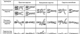
Is it possible to connect wires by twisting
Very often, especially in old houses, we start removing old wallpaper, unscrewing old sockets, disassembling dilapidated junction boxes and what do we see: a lot of wires twisted together and wrapped in insulation:
I know that many electricians still twist wires this way and consider it the most reliable. However, from a fire safety point of view, no firefighter will approve of electrical connections in an apartment made only by twisting.
The fact is that sometimes you have to connect wires of different sections and different materials, for example, copper and aluminum wires. And it is precisely for such cases that twisting is unacceptable. For example, with the same load on the network, it will act differently on thick and thin wires twisted together, one of which will feel good, and the other will heat up.
Colors for 220V and 380V networks
Installation of single- and three-phase electrical networks is facilitated if the wiring is made with multi-color wire. Previously, a flat two-core white wire was used for single-phase residential wiring. During installation and repair, to eliminate errors, it was necessary to ring each core individually.
The production of cable products with colored cores in different colors reduces the labor intensity of the work. To indicate phase and zero in single-phase wiring, it is customary to use the following colors:
- red, brown or black - phase wire;
- other colors (preferably blue) - neutral wire.
The phase markings in a three-phase network are slightly different:
- red (brown) - 1st phase;
- black - 2 phase;
- gray (white) - 3 phase;
- blue (blue) - working zero (neutral)
- yellow-green - grounding.
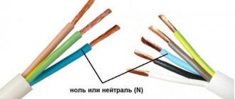
Domestic cable products comply with the standard for core coloring, so a multiphase cable contains differently colored cores, where the phase is white, red and black , the neutral is blue , and the ground is yellow-green conductors.
When servicing networks installed according to modern standards, it is possible to accurately determine the purpose of the wires in the junction boxes. If there is a bundle of multi-colored wires, the brown one will definitely be phase. The neutral wire in distribution boxes has no branches or breaks. The exception is branches to multi-pole switching devices with complete circuit breaking.
Instructions for replacing the electric kettle stand plug
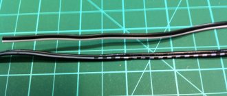
Let's take an old stand for an electric kettle with a wire and a molded C6 plug. The power cord for electric kettles usually does not differ in length; however, if necessary, replacing the plug may be accompanied by lengthening the cord. If there is no such need, then 15 centimeters is enough to connect to the network.
After this, being careful not to damage the insulation of the wires, cut the sheath along the cord to a length of up to 10 cm and take the wires out. Please note that the insulation itself does not need to be cut. So how do you connect a three-core cable to a plug? A standard cable from the inside consists of three cores, designated by different colors: brown - phase, light blue - neutral, yellow-green - grounding conductor.
Next, adjust the length of the conductors so that the places where the cores are twisted are shifted relative to each other by 1-2 centimeters. Please note that wires of the same color are connected to each other. It is necessary.
Then remove the insulation from the conductors of the wires by about 1.5 cm. If one of the wires is three-core, and the second is without a grounding yellow-green wire, then there is no need to clean the free edge, since you will not connect it anywhere - it remains free .
The protected conductors are connected to each other by twisting. For good contact, three turns of entanglement will be enough.
Coloring in DC networks
For DC networks, it is customary to mark conductors connected to the positive pole in red, and to the negative pole in black or blue. In bipolar circuits, blue insulation is used to mark the midpoint (zero) of the power supply.
There are no standards for color codes on multi-voltage circuits. What color are the plus and minus wires, what voltage is in them - this can only be determined by the decoding of the device manufacturer, which is often given in the documentation or on one of the walls of the structure.
Example: computer power supply or car wiring.
Automotive wiring is characterized by the fact that in it the circuits with positive voltage of the on-board network are red or its shades (pink, orange), and those connected to ground are black. The remaining wires have a specific color, which is determined by the car manufacturer.