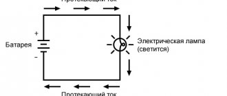
What it is
Current resonance is a type of state of an electrical circuit when the general appearance of current indicators coincides in phase with the voltage level, and the reactive power is zero or it is presented in active form.
. Current resonance
This scenario is typical for alternating current and has not only positive properties, but also some undesirable consequences. Thus, thanks to resonance, radio technology, automation and wire telephony work, but at the same time, overvoltages and malfunctions in the electrical system occur.
Definition from the textbook
Under what conditions does it occur?
The condition for this phenomenon to occur is equal conductor frequencies, where BL=BC. That is, capacitive and inductive conductivity must be equal. Only then is a similar phenomenon of current resonance observed in an electrical circuit. It can be either positive or negative. Any radio receiver has an oscillating circuit, which, due to inductive or capacitive changes, is tuned to the desired radio wave signal. In another case, this leads to voltage surges or current in the circuit and an emergency situation occurs.
In laboratory conditions, it occurs at a time when the capacitance changes and the inductance of the coil L does not change. In this case, the formula looks like Bc=C
Under what conditions does it occur?
What is resonance?
Definition of the phenomenon by TOE: electrical resonance occurs in an electrical circuit at a certain resonant frequency, when some parts of the resistance or conductivity of the circuit elements cancel each other. In some circuits, this occurs when the impedance between the input and output of the circuit is almost zero and the signal transfer function is close to unity. In this case, the quality factor of this circuit is very important.
Connection of two branches at resonance
Signs of resonance:
- The components of the reactive branches of the current are equal to each other IPC = IPL, antiphase is formed only when the net active energy at the input is equal;
- The current in individual branches exceeds the entire current of a particular circuit, while the branches are in phase.
In other words, resonance in an AC circuit implies a special frequency, and is determined by the values of resistance, capacitance and inductance. There are two types of current resonance:
- Consistent;
- Parallel.
For series resonance, the condition is simple and is characterized by minimal resistance and zero phase, it is used in reactive circuits, and it is also used in branched circuits. Parallel resonance or the concept of an RLC circuit occurs when the inductive and capacitive inputs are equal in magnitude but cancel each other out since they are at an angle of 180 degrees from each other. This connection must be constantly equal to the specified value. It has received wider practical application. The sharp minimum impedance that it exhibits is beneficial for many electrical household appliances. The sharpness of the minimum depends on the resistance value.
An RLC circuit (or circuit) is an electrical circuit that consists of a resistor, inductor, and capacitor connected in series or parallel. The RLC parallel oscillating circuit gets its name from the abbreviation of the physical quantities representing resistance, inductance and capacitance, respectively. The circuit forms a harmonic oscillator for the current. Any oscillation of the current induced in the circuit fades over time if the movement of the directed particles is stopped by the source. This resistor effect is called attenuation. The presence of resistance also reduces the peak resonant frequency. Some resistance is unavoidable in real circuits, even if a resistor is not included in the circuit.
Voltage resonance
This phenomenon occurs when a coil with a capacitor with the same reactance is connected in series to the generator.
Please note that situations where only capacitance and inductance are reactive exist only ideally. But in reality there is always wire resistance, albeit insignificant.
With the resonant effect, the capacitor and inductor exchange energy. When the generator starts, the capacitor begins to accumulate energy, and then, after turning off, oscillations begin to occur as a result of the exchange.
A circuit that includes capacitance and inductance is called an oscillatory circuit.
Periodicity is calculated by Thompson's formula:
Since resistance depends on frequency, accordingly, as the frequency increases, the resistance of the inductance increases, while the resistance of the capacitance, on the contrary, decreases.
The overall resistance indicator will decrease noticeably when the resistances are the same.
The main parameters of the circuit include frequency and transmission coefficient. If you look at a circuit with four poles, it becomes clear that the transfer coefficient is equal to the quality factor (Q).
In resonance, the higher the quality factor, the higher the voltage on the circuit elements compared to the voltage on the generator.
In the circuit, power readings drop due to resistance. The supplier's energy is used only to support the oscillations.
Application
Almost all power electrical engineering uses just such an oscillatory circuit, say, a power transformer. The circuit is also necessary for setting up the operation of a TV, capacitive generator, welding machine, radio receiver; it is used by the “matching” technology of television broadcast antennas, where you need to select a narrow frequency range of some of the waves used. The RLC circuit can be used as a band-pass filter, notch filter, for low-pass or high-pass distribution sensors.
It will be interesting➡ Flux for soldering: features, types, tips
Resonance is even used in aesthetic medicine (microcurrent therapy) and bioresonance diagnostics.
Principle of current resonance
We can make a resonant or oscillating circuit at its natural frequency, say, to power a capacitor, as the following diagram demonstrates:
Circuit for powering a capacitor
The switch will be responsible for the direction of vibration.
Circuit: resonant circuit switch
The capacitor stores all the current at the moment when time = 0. Oscillations in the circuit are measured using ammeters.
Scheme: the current in the resonant circuit is zero
Directed particles move to the right. The inductor receives current from the capacitor.
When the polarity of the circuit returns to its original form, the current returns to the heat exchanger.
Now the directed energy goes back into the capacitor, and the circle repeats again.
In real mixed circuit circuits there is always some resistance which causes the amplitude of the directed particles to grow smaller with each circle. After several changes in the polarity of the plates, the current decreases to 0. This process is called a damped sine wave signal. How quickly this process occurs depends on the resistance in the circuit. But the resistance does not change the frequency of the sine wave. If the resistance is high enough, the current will not fluctuate at all.
The AC designation means that the energy leaving the power supply oscillates at a specific frequency. An increase in resistance helps to reduce the maximum size of the current amplitude, but this does not lead to a change in the resonance frequency. But an eddy current process can form. After its occurrence, network interruptions are possible.
Conditions for the occurrence of resonance
Just like voltage resonance, current resonance occurs when the frequency of the energy source is equal to the resonant frequency ωр, and
The mode of an electrical circuit with parallel connection of sections with inductance and capacitance, characterized by equality of inductive and capacitive conductivities, is called current resonance.
First, let's look at this mode for an idealized circuit. In this circuit, ideal coils L and capacitor C are connected in parallel with resistor R, in which energy losses are not taken into account.
On the issue of current resonance
Reactive conductivities depend on the frequency of forced oscillations. For the circuit under consideration: active conductivity reactive conductivities At resonance of currents From here the resonant frequency is determined: The expression for the resonant frequency in this case is the same as that which was obtained when considering voltage resonance and for the frequency of natural oscillations in a lossless circuit. Current resonance, as well as voltage resonance, can be obtained by changing the parameters L and C or changing the frequency of the energy source.
Parallel connection of capacitor and coil
Rice. 1
In this circuit, the common parameter for the two branches is the voltage U. The first branch - the inductive coil - has active resistance R and inductance L. The resulting resistance Z1 and current I1 are determined by the formula:
Since the resistance of this branch is complex, the current in the branch lags in phase from the voltage by an angle φ1 = arctan(R/XL). Let's show this in a vector diagram.
Resonance of currents in a circuit with alternating current
The flow of current inside an electrical circuit with a serial, parallel or mixed type of connection of elements causes different operating modes to be obtained.
Thus, the resonance of an electrical circuit is a mode of a section that contains elements of inductive and capacitive type, and the phase shift angle between current values and voltage values is zero.
In the capacitor and coil part connected in parallel, equal reactance is observed, which causes resonance.
It should also be taken into account that the coil part and the capacitor are characterized by a complete absence of active resistance, and the equality of the reactance makes the total current indicators inside the unbranched part of the electrical circuit and large current values in the branches zero.
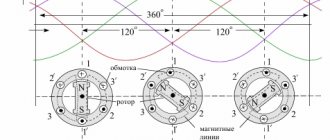
When an inductive coil and a capacitor are connected in parallel, an oscillatory circuit is obtained, which is distinguished by the presence of an oscillating generator that is not connected to the circuit, which makes the system closed.
A phenomenon accompanied by a sharp decrease in the amplitude of the current values of the external circuit, which is used to power a parallel-connected capacitor and a conventional inductive coil when the frequency of the applied voltage approaches the resonance frequency, is called current or parallel resonance.
It will be interesting➡ Total current law for a magnetic field
Inductance and capacitance in a variable current circuit
Capacitance in a line with a constant current looks like an open circuit segment, induction is represented by a conductor. With alternating current, the reactive resistor analogue is represented by coils with condensation devices.
Reactance depends on the value of capacitance or inductance, as well as the frequency of the variable current.
Looking at the calculation of the reactive value, it becomes noticeable that having certain values of the inductive or capacitive element, their difference is equal to zero, and, as a result, the remainder will contain active resistance. This situation has some other nuances.
Resonant circuit calculation
It must be remembered that the phenomenon represented by current resonance requires very competent and careful calculation of the resonant circuit. It is especially important to perform a correct and accurate calculation when there is a parallel connection, which will prevent the development of interference within the system. In order for the calculation to be correct, it is necessary to determine the power indicators of the electrical network. The average standard power that is dissipated under the conditions of a resonant circuit can be expressed in terms of rms current and voltage.
Under resonance conditions, the standard power factor is unity, and the calculation formula is:
Calculation formula
In order to correctly determine zero impedance under resonance conditions, you will need to use the standard formula:
Resonance curves
The resonance of the vibrational frequency is approximated by the following formula:
Resonance of the oscillatory circuit
In order to obtain the most accurate data from the formulas, it is recommended not to round off all values obtained during the calculation process. Some physicists calculate the values of the resonant circuit in accordance with the method of vector diagram of active current quantities. In this case, competent calculation and correct configuration of devices guarantees decent savings under the condition of alternating current.
Resonant circuits are used primarily to isolate a signal at the desired frequencies as a result of filtering other signals, so independent circuit calculations must be extremely accurate.
RLC circuit quality factor
Resonance circuits are used to isolate a signal at a desired frequency, filtering out other signals at other frequencies. If we plot vertically the effective value of the forced oscillation current in the RLC circuit, and horizontally the frequency of the variable EMF generated by the source, we will get a resonant curve of this RLC circuit, similar to the one shown in the figure:
If the resonance curve has a sharp peak at the resonant frequency, the circuit is said to have high "selectivity". The parameter characterizing this property is called quality factor . The quality factor of an RLC circuit is defined as the ratio of its resonant frequency to the width of the resonant band at half-maximum:
The quality factor of an RLC circuit depends on the value of the active resistance. The lower the active resistance, the higher the quality factor for given values of inductance and electrical capacitance. For an RLC circuit, the quality factor is determined by the formula:
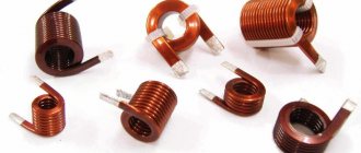
Inductance and capacitance reactances
Inductance is the ability of a body to accumulate energy in a magnetic field. It is characterized by a phase lag between the current and the voltage. Typical inductive elements are chokes, coils, transformers, electric motors.
Capacitance refers to elements that accumulate energy using an electric field. Capacitive elements are characterized by a phase lag between voltage and current. Capacitive elements: capacitors, varicaps.
Their main properties are given; the nuances are not taken into account within the scope of this article.
In addition to the listed elements, others also have a certain inductance and capacitance, for example in electrical cables distributed along its length.
Vector diagram for the first branch
Rice. 2
Let's project the current vector I1 onto the coordinate axes. The horizontal component of the current will be the active component I1R, and the vertical component will be I1L. The quantitative values of these components will be equal:
A capacitor is included in the second branch. His resistance
This current is 90° ahead of the voltage in phase. To determine the current I in the unbranched part of the circuit, we use the formula:
Its value can also be obtained graphically by adding the vectors I1 and I2 (Fig. 3). The shift angle between current and voltage will be denoted by the letter φ. Here, various modes of operation of the circuit are possible. At φ = +90°, capacitive current will be predominant, at φ = -90°, inductive current will be predominant.
Operating principle of resonant currents
A visual representation of current resonance is given by an oscillatory circuit used in electronic circuits. It consists of a capacitor with capacitance C and a coil with inductance L, connected in parallel. In the process of transferring energy from the electric field of a capacitor to the magnetic field of an inductance, self-damping oscillations arise with a certain frequency. The occurrence of oscillations occurs due to active resistance R, which prevents the free passage of current.
The phenomenon of current resonance appears in a circuit where a capacitor and a coil are connected in parallel. Their ratings are selected in such a way that the currents flowing through C and L are equal. Therefore, in the C-L circuit the current will be higher than its value in the remaining sections of the circuit.
The operating principle of such a circuit is as follows. When power is applied, the capacitor accumulates a certain amount of charge equal to the rated voltage of the current source. After this, the source is turned off, and the capacitor is closed into the circuit circuit so that a discharge is sent to the coil. Current passes through it, thereby causing the generation of a magnetic field. As a result, an electromotive force of self-induction is created, directed towards the current.
The maximum value of the magnetic field is achieved when the capacitor is completely discharged. Thus, all the energy accumulated by the capacitor is transformed into a magnetic field of inductance. The charged particles continue to move due to the self-induction of the coil.
Since there is no longer a countercurrent from the discharged capacitor, it is recharged, but with a changed polarity. This causes the field of the coil to be converted into a charge on the capacitor and the whole process repeats. The active component R leads to a gradual decay of the oscillations. This is the main essence of resonance.
Operating principle
Current resonance can be seen in the inner surface of an electrical circuit that has a parallel coil, resistor and capacitor connection. The main principle of how a standard device works is not difficult to understand.
You may be interested in: Features of solder for soldering
When the electrical power is turned on, charge accumulates inside the capacitor unit to the rated voltage. At this time, the power source is turned off and the circuit is closed into a circuit. This moment is accompanied by a transfer of the discharge to part of the coil. Next, the current readings that pass through the coil generate a magnetic field. An electromotive independent inductive force is created in the direction of the counter current. With a complete capacitor discharge, the current indicators increase as much as possible. The amount of energy becomes a magnetic induction field. As a result, this cycle is repeated, and the coil field is converted into a capacitor charge.
Principle of operation
Concept of resonance currents. Conditions for its occurrence and methods of implementation
Current resonance is a resonance that occurs in a parallel oscillating circuit when it is connected to a voltage source whose frequency coincides with the natural frequency of the circuit.
Current resonance condition: , .
B1 – reactive conductivity of the first branch,
B2 – reactive conductivity of the second branch.
It will be interesting➡ Instrumentation mechanic: professional features and difficulties
A method of exciting oscillations in an electrical circuit, which consists in generating oscillations by regulating the signal that controls the excitation of oscillations.
Resonance of currents and its signs
The mode in which, in a circuit containing parallel branches with inductive and capacitive elements, the current of the unbranched section of the circuit is in phase with the voltage (φ = 0), is called current resonance.
Signs of current resonance:
The reactive components of the branch currents are equal to IPC = IPL and are in antiphase in the case when the input voltage is purely active;
The branch currents exceed the total circuit current, which has a minimum value and are in phase.
Lecture for a college in electrical engineering on the topic “Resonance in an AC circuit.”
Lecture 8.
Circuit with active resistance, inductance and capacitance.
Resonant mode of operation of the circuit. Voltage resonance. Resonance of currents. Power factor. A circuit with active resistance, inductance and capacitance.
A circuit with active resistance, inductance and capacitance represents a common
the case of a series connection of active and reactive resistances is
series oscillatory circuit.
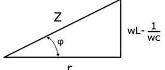
Rice.
a) A circuit with a resistor, an inductor and a capacitor, b) A vector diagram of the circuit, c) a triangle of circuit resistances R, X L and X C
We take the current phase to be zero: i
= I m sin
* t;
Then u R =
U m sin
* t;
u L = U m sin (
* t + /2);
u C = U m sin (
* t - /2)
Let's build a vector diagram for ХL>ХС, that is, UL= I ХL> UC= I ХC
The resulting voltage vector U closes the polygon of vectors UR, UL and UC. The UL+UC vector determines the voltage across the inductance and capacitance. As can be seen from the diagram, this voltage can be less than the voltage in each of the sections separately. This is explained by the process of energy exchange between inductance and capacitance.
Since the modulus of the vector UL+UC is calculated as the difference between the effective values UL—UC, then
and therefore
Ohm's law for this circuit in this case,
where Z is the total resistance of the circuit.
The difference between inductive and capacitive reactance XL—XC=X is called
reactance of the circuit.
When XL>XC the reactance is positive and the circuit resistance is active-inductive in nature. In this case, the phase shift angle φ>0 is positive.
With XLC, the reactance is negative and the circuit resistance is active-capacitive in nature. In this case, the phase shift angle φ<0 is negative.
Resonant mode of operation of the circuit.
The resonant mode of operation is a mode in which the resistance is purely active. In relation to the power source, the circuit elements behave in resonant mode as an active resistance, so the current and voltage in the unbranched part are in phase. The reactive power of the circuit is equal to zero.
A distinction is made between voltage resonance and current resonance.
Voltage resonance.
Voltage resonance occurs in a series oscillating circuit circuit when the current in the circuit coincides with the phase voltage φ = 0°.
a) b) c)
Rice. a) Series resonant circuit, b) Vector diagram of the circuit at X L =X C , c) resonant curve of the series circuit.
The reactance of the series circuit is zero X=0
at
X L =X C .
Since X L
=
L
; X c = 1/
C ;
= 2
f then
Resonant frequency With voltage resonance, the source frequency is equal to the natural frequency of the circuit.
Voltage resonance condition:
a) circuit resistance Z = R
minimal and purely active;
b) the circuit current is in phase with the source voltage and reaches its maximum value;
c) the voltage on the inductive coil is equal to the voltage on the capacitor and each individually can be many times higher than the voltage at the circuit terminals.
The quantity is called the characteristic impedance of the circuit.
The resonance curve shows the dependence of the effective value of the current in the circuit on the source frequency at a constant natural frequency of the circuit.
Let's place the dependence of inductive and capacitive reactance on the source frequency on one graph.
Rice. Dependence of reactance X on source frequency.
At frequencies close to f
0, the reactance is small and the loop current is large.
Voltage resonance is widely used in radio engineering and electronics to isolate
signals of a given frequency.
Resonance of currents.
Resonance of currents occurs in an unbranched section of the circuit of a parallel oscillating circuit when the current coincides with the voltage in phase φ = 0°.
a) b)
Rice. a) Parallel oscillatory circuit, b) Vector diagram with current resonance.
If IR is small, then Ic = ILP
Current resonance condition:
a) circuit impedance Z is maximum and fully active,
b) the current in the unbranched part of the circuit is in phase with the voltage and is very small,
c) the reactive component of the current in the coil is equal to the reactive component of the current in the capacitor.
In order for the current I
in the unbranched part of the circuit is in phase with the voltage,
reactive component of the current of the inductive branch I
Lp must be equal in magnitude to current
capacitive branch I
C.
The active component of the current in the inductive branch I
La turns out to be
equal to the source current I
.
Let's determine the circuit resistance under the assumption R
<<
X
L.
Let us formulate the signs of current resonance:
a) circuit resistance Zk is maximum and purely active;
b) the current in the unbranched part of the circuit is in phase with the source voltage and
reaches almost a minimum value;
c) the reactive component of the current in the coil is equal to the capacitive current, and these currents
can be many times higher than the source current.
Power factor.
By analogy with the resistance triangle, for a series connection of a resistor, inductor and capacitor, you can obtain a triangle of voltages and powers.
Rice. Resistance triangle and impedance calculation
Rice. Power triangle and total power calculation
Active power developed by the generator in nominal mode P = I nom
U nom cos φ
Full use of the generator power occurs at cos
φ = 1
.
In this case, the active power is maximum and equal to the rated apparent power S nom = I nom U nom
A real AC electrical circuit necessarily contains reactance. This increases heating losses.
Cos
φ is called the power factor.
cos
φ = P / S is the ratio of active power to apparent power.
It shows how much of the electrical energy produced by an AC source is used to perform useful work.
A decrease in cos
φ
leads to an increase in heat losses in the transmission line, which grow in inverse proportion to the square of the power factor.
To fully utilize the rated power of generators and reduce heat losses, it is necessary to increase the cos φ
of energy receivers to values close to unity (0.95-1.0).
To increase cos
φ,
capacitor banks are connected in parallel to the energy receiver.
Thanks to this, the capacitance and line become the source of reactive energy for the receiver
transmission is unloaded from reactive current.
In practice, receivers with satisfactory cos
φ
include asynchronous motors as industrial drives.
cos φ
value ranges from 0.1-0.3 at idle and 0.8-0.85 at rated load.
Application in practice
Let's consider the benefits and harms of resonance of currents and voltages. The resonance phenomenon has brought the greatest benefit to radio transmitting equipment. In simple words, the receiver circuit has a coil and a capacitor connected to the antenna. By changing the inductance (for example, by moving the core) or the capacitance value (for example, with an air variable capacitor), you tune the resonant frequency. As a result, the voltage on the coil increases and the receiver catches a certain radio wave.
These phenomena can cause harm in electrical engineering, for example, on cable lines. The cable represents inductance and capacitance distributed along its length if voltage is applied to the long line in no-load mode (when there is no load connected at the end of the cable opposite the power source). Therefore, there is a danger that an insulation breakdown will occur; to avoid this, a load ballast is connected. Also, a similar situation can lead to failure of electronic components, measuring instruments and other electrical equipment - these are dangerous consequences of this phenomenon.