What is current work
With the chaotic movement of charged particles in a conductor, the electric field will perform work, which they decided to call the work of current. The definition of current work is as follows: it is the work of an electric field to transfer charges inside a conductor.
Important! In addition to electrical forces, magnetic forces also act on the conductor, which can also do work. However, under normal conditions it will be very small.
Movement of charges in a conductor
Current power through the capacitor
Let an alternating voltage be applied to the capacitor. As we know, the current through a capacitor is ahead of the voltage in phase by:
For instantaneous power we get:
A graph of instantaneous power versus time is shown in Fig. 3.
Rice. 3. AC power through capacitor
What is the average power value? It corresponds to the “middle” of the sinusoid and in this case is equal to zero! We see this now as a mathematical fact. But it would be interesting to understand from a physical point of view why the current power through the capacitor turns out to be zero.
To do this, let's draw graphs of voltage and current in the capacitor over one oscillation period (Fig. 4).
Rice. 4. Voltage across the capacitor and current through it
Let's consider all four quarters of the period sequentially.
1. First quarter
, . The tension is positive and increasing. The current is positive (flows in the positive direction), the capacitor is charged. As the charge on the capacitor increases, the current decreases.
Instantaneous power is positive: the capacitor stores energy coming from the external circuit. This energy arises due to the work of an external electric field that pushes charges onto the capacitor.
2. Second quarter
, . The tension remains positive, but is subsiding. The current changes direction and becomes negative: the capacitor is discharged against the direction of the external electric field. At the end of the second quarter, the capacitor is completely discharged.
Instantaneous power is negative: the capacitor releases energy. This energy returns to the circuit: it is used to do work against the electric field of the external circuit (the capacitor, as it were, “pushes” the charges in the direction opposite to the one in which the external field “wants” to move them).
3. Third quarter
, . The external electric field changes direction: the voltage is negative and increases in magnitude. The current is negative: the capacitor is charging in the negative direction.
The situation is completely similar to the first quarter, only the signs of voltage and current are opposite. The power is positive: the capacitor again stores energy.
4. Fourth quarter
, . The voltage is negative and decreases in magnitude. The capacitor is discharged against the external field: the current strength is positive.
Power is negative: the capacitor returns energy to the circuit. The situation is similar to the second quarter - again with the replacement by replacing the signs of current and voltage with opposite ones.
We see that the energy taken by the capacitor from the external circuit during the first quarter of the oscillation period is completely returned to the circuit during the second quarter. This process is then repeated again and again. This is why the average power consumed by a capacitor turns out to be zero.
Units
Any physical quantity that can be converted into energy will be measured in Joules (J). 1 Joule is equal to the work done to move a point to which a force equal to 1 Newton is applied multiplied by a Path of 1 meter. It turns out that 1 J = 1 N · 1 m.
The unit of power is Watt (W). It is equal to 1 J of work done per unit of time of 1 s. Thus, 1 W = 1 J: 1 s
Power unit
Calculation formula
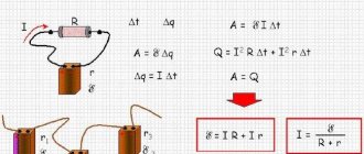
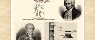
In 1841, the English scientist James Joule formulated a law for finding a quantitative measure of the thermal effect of electric current. In 1842, the same law was also discovered by the Russian physicist Emilius Lenz. Because of this, it received the double name of the Joule-Lenz law. In general, the law is written as follows: Q = I² • R • t.
It is quite general in nature, since it does not depend on the natural forces that generate the current. Today this law is actively applied in everyday life. For example, to determine the degree of heating of the tungsten filament used in light bulbs.
Joule-Lenz law
The Joule-Lenz law determines the amount of heat generated by a current. But, nevertheless, this will help to find out what formulas are used to calculate the work of the electric field. This is because it subsequently manifests itself in the form of heating of the conductor. This suggests that the work done by the current is equal to the heat of heating of the conductor (A=Q). Work of electric current, formula: A= I² • R • t. This is not the only formula for finding a job. If you use Ohm's law for a section of the chain (I=U:R), then you can derive two more formulas: A=I•U•t or A=U²:R.
You might be interested in Hand press pliers
Portraits of Joule and Lenz
The general formula for calculating power is that it is directly proportional to work and inversely dependent on time (P=A:t). If we talk about power in an electric field, then based on the previous formulas, we can create as many as three: P = I² • R; P=I•U; Р=U²:R.
Ohm's law for a circuit section
Interpretation of the law of conservation of energy. Joule-Lenz law
Ohm's law for a homogeneous section of a circuit with resistance R is reflected by the formula:
RI=U
Let's multiply both sides of the expression by IΔt and get the relation:
RI2∆t=UI∆t=∆A.
The result obtained is an expression of the law of conservation of energy for a homogeneous section of the chain.
Definition 2
The work ΔA of electric current I flowing through a stationary conductor with resistance R is converted into heat ΔQ released on the conductor.
∆Q=∆A=RI2∆t
This law is called the Joule-Lenz law.
The law bears the name of two famous physicists at once, since it was established experimentally by both of them independently of each other.
Definition 3
The power of the electric current is the ratio of the current work ΔA to the time interval Δt during which this work was performed.
It can be said more simply: power is work done per unit of time. Let us write down the formula connecting the work of the current and its power:
P=∆A∆t=UI=I2R=U2R
The work of an electric current is expressed in joules (J), the current power is measured in watts (W), time is measured in seconds (s): 1 W = 1 J1 s. The current power is measured using a wattmeter, and the work is calculated as a result of multiplying the current strength, voltage and time of current flow through the circuit: A=IUt.
Next, we will analyze a complete direct current circuit, including a source with an electromotive force δ and internal resistance r and an external homogeneous section with resistance R.
Definition 4
Ohm's law for a complete circuit looks like this:
(R+r)I=δ
Do you need help from a teacher? Describe the task - and our experts will help you! Describe the task
Let's multiply both sides of the expression with Δq=IΔt and get a relationship that will serve as an expression of the law of conservation of energy for a complete DC circuit:
RI2∆t+rI2∆t=δI∆t=∆Ast
The left side of the expression contains ΔQ=RI2Δt (heat that is released on the external section of the circuit during the time Δt) and ΔQist=rI2Δt (the heat that is released inside the source during the same time).
The expression δIΔt is equal to the work of external forces ΔAst that act inside the source.
Definition 5
When electric current flows through a closed circuit, the work of external forces ΔAst is converted into heat, which is released in the external circuit (ΔQ) and inside the source (ΔQist).
∆Q+Qist=∆Ast=δI∆t
The following fact should be noted: the work of the electric field is not included in the indicated ratio. When current passes through a closed circuit, the electric field does no work; This means that heat is produced only through external forces that act inside the source. The electric field here redistributes heat between different sections of the circuit.
The external circuit can be not only a conductor with resistance R, but also some device that consumes power, for example, a DC motor. Then R must be regarded as the equivalent load resistance. The energy that is released in the external circuit has the ability to be partially or completely converted into both heat and other types of energy, for example, into mechanical work performed by an electric motor. Thus, the topic of using the energy of a current source is of great practical importance.
It will be interesting➡ Twilight switches
Kirchhoff's rules
To simplify the calculation of branched chains containing heterogeneous sections, special rules were created - Kirchhoff's rules
:
- The algebraic sum of current strengths for each node is equal to zero: \(~\pm I_1 \pm I_2 \pm \ldots \pm I_N = 0\) . Sign rule for currents at nodes
:- if current flows into the node, then we take the current strength with a “+” sign,
- if current flows out of the node, then with a “–” sign.
- The algebraic sum of the EMF in a closed circuit is equal to the algebraic sum of the products of current strengths and resistances of each section of this circuit: ±I
1·(
R
1 +
r
1) ±
I
2·(
R
2 +
r
2) ± … ±
I
n·(
R
n+
r
n) = ±
ℰ
1 ±
ℰ
2 ± … ±
ℰ
k.
Sign rule for currents in circuits
:- if the direction of the current coincides with the direction of bypassing the circuit, then we take the current strength with a “+” sign,
- if the direction of the current does not coincide with the direction of bypassing the circuit, then we take the current strength with a “–” sign.
For example, in Figure 4 with the “+” sign we take I
1 and
I
4, with the “–” sign we take
I
2,
I
3 and
I
5. Then for node
A
we can write that
I
1 -
I
2 -
I
3 +
I
4 -
I
5 = 0.
Rice. 4
Sign rule for EMF in circuits
:
- if the direction of the source current coincides with the direction of bypassing the circuit, then we take the source emf with the “+” sign,
- if the direction of the source current does not coincide with the direction of bypassing the circuit, then the source emf is taken with the “–” sign.
Mnemonic sign rule for EMF in circuits
:
- the sign of the EMF corresponds to the sign of the last terminal of the source when passing through the source by bypassing the circuit.
For example, in Figure 5 we choose to walk around the circuit clockwise.
Rice. 5
For the
ABC
with the “+” sign we take
I
2 and
I
3,
ℰ
3, with the “–” sign we take
ℰ
2. Then
I
2·(
R
2 +
r
2) +
I
3·(
R
3 +
r
3) = -
ℰ
2 +
ℰ
3.
ACD
contour with the “+” sign we take
ℰ
1, with the “–” sign we take
I
1,
I
3 and
I
4,
ℰ
3. Then -
I
1·(
R
1 +
r
1) -
I
3·(
R
3 +
r
3) -
I
4·
R
4 =
ℰ
1 -
ℰ
3.
If we take into account that I
1 =
I
4, then -
I
1 (
R
1 +
r
1 +
R
4) -
I
3 (
R
3 +
r
3) =
ℰ
1 -
ℰ
3.
Note
: For each circuit, the direction of its bypass, which determines the signs of currents and EMF, is chosen arbitrarily. If, as a result of solving the problem, a negative current value is obtained in some section, this means that the current in this section flows in the direction opposite to the selected circuit bypass.
Work, power and thermal effect of electric current
The work done by an electric current on a section of a circuit is equal to the product of the voltage on that section, the current strength and the time during which the work is performed. The unit of work is the joule (1 J).
The work of an electric current on a section of a circuit is equal to the product of the voltage at the ends of this section by the current strength and the time during which the work was performed.
Total power is a value equal to the product of the effective values of the periodic electric current.
The thermal effect of electric current is understood as the release of thermal energy during the passage of current through a conductor. When current passes through a conductor, the free electrons that create the current collide with ions and atoms of the conductor, heating it
Work of electric current
Let's find out how the work of current in an electrical circuit is calculated.
The total work done by the current in the section of the circuit that is the consumer can be found using formula (15.10):
where is the voltage on a section of the circuit, and is the charge transferred through the cross-section of the conductor during the passage of current. Since then
Since the voltage and current in a section of the circuit can be measured with a voltmeter and ammeter, formula (17.1) is convenient in practice for calculating the total work of the current. Using this formula, work can be calculated regardless of what type of energy the electrical energy is converted into in the section of the circuit under consideration.
When all electrical energy is converted into internal energy (i.e., spent on heating a section of the circuit), formula (16.11) is valid: . Substituting this expression into (17.1), we obtain another formula for calculating the work of the current in the section of the circuit without e. d.s.:
Since , formula (17.1) can also be written as follows:
So, when calculating the work of the current in a section of the circuit without e. d.s. you can use any of the formulas (17.1) - (17.3).
Let us now consider the section of the chain with e. d.s. Let us remember that when a consumer has a counter-e. d.s., then electrical energy is partially converted into internal energy and partially into other types of energy. The electrical energy consumed in this case is calculated using formula (17.1). It remains to establish how to calculate the amount of electrical energy that has been converted into internal energy in such a section of the circuit.
Since the voltage drop shows how much electrical energy has been converted into the internal energy of a section of the circuit during the passage of a unit charge, then if a charge passes through a section of the circuit, the increase in the internal energy of the section will be equal to , but since , we get . Thus, the work of the current, which determines the electrical energy that is spent on thermal action in a given section of the circuit, is expressed by formula (17.3):
Note that this formula is valid for any section of the circuit, including the generator.
The work of external forces in the generator, which evaluates the amount of electrical energy received in it due to other types of energy, is found from the relationship (16.8). Since we get
Formula (17.4) can also be applied to the consumer. In this case it means counter-e. d.s., and work A determines how much electrical energy is converted into mechanical or chemical energy.
Recall that when calculating in SI, work is obtained in joules (watt-seconds). However, in electrical engineering, work is usually expressed in watt-hours or kilowatt-hours:
Because an hour contains 3.6. 103 s, then to calculate the work of the current in watt-hours, it is enough to substitute time in hours (instead of seconds) into the above formulas. Note that a device for measuring current work is called an electric meter, and the cost of a unit of current work is called a tariff. For example, for the population of Moscow the tariff is 4 kopecks. (or 2 kopecks) per 1 kWh.
Electric current power
Recall that power is a quantity that characterizes the speed at which work is performed. The current power in a section of the circuit is measured by the work done by the current per unit time. Since in electrical engineering power is usually denoted by P, we have
The SI unit of power is the watt: 1 W=1 J/s.
Substituting into (17.5) the values of A from the formulas of the previous paragraph, we obtain formulas for calculating power in electrical circuits. Current power in the section of the circuit without e. d.s. can be calculated using any of the following formulas (when calculating, you must choose the one that is more convenient for the case under consideration):
When the consumer has e. d.s. , formula
gives the total current power, and the formula
gives the current power spent on thermal action. Formula
allows you to determine the current power spent on obtaining other types of energy, except internal. For a generator, formula (17.9) determines the power spent on generating electrical energy in the generator.
When making calculations, it should be remembered that the current power in the entire external circuit for any connection is equal to the sum of the powers in individual sections of the circuit. Note that the current power in the supply wires is often called power loss.
It will be interesting➡ Magnetic induction. Definition and description of the phenomenon
Thermal effect of electric current
Joule-Lenz law. The thermal effect of current was studied experimentally by the English scientist J. Joule and the Russian physicist E. Lenz. The amount of heat generated by the current in the conductor is equal to the work of the electric field to overcome the resistance of the conductor:
Formula (17.10) is a mathematical expression of the Joule-Lenz law: the amount of heat generated by the current in a conductor is directly proportional to the resistance of the conductor, the square of the current strength and the time it passes. Let us note once again that formula (17.10) allows us to calculate the amount of heat generated by the current in any section of the circuit with resistance .
When connecting conductors in series with resistances and (Fig. 17.1, a), the amount of heat generated in them can be expressed as follows:
where does it follow that
Consequently, the amount of heat generated by the current in each conductor in a series connection is directly proportional to the resistance of these conductors.
When connecting two sections of a circuit in parallel without e. d.s. With resistances and (Fig. 17.1, b) the amount of body emitted by current in each section separately is equal to
where
The amount of heat released by current in parallel-connected sections of a circuit without e.g. d.c., inversely proportional to the resistance of these sections.
From (17.11) and (17.12) it is clear that with a series connection, a larger amount of heat is released in a conductor with greater resistance, and with a parallel connection - with less.
Work and current power. Electromotive force. Ohm's law for a complete circuit
Voltage. Electrical capacity. Capacitors Read more: Electric current in gases. Types of gas discharges and their application. The concept of plasma
41. Work and current power. Electromotive force. Ohm's law for a complete circuit.
The work done by the forces of the electric field that creates an electric current is called the work of the current. The work done by A of the current in a section with resistance R during time Dt is equal to . The power of the electric current is equal to the ratio of work to the time of completion, i.e. . Work is expressed, as usual, in joules, power - in watts. If no work is done on a section of the circuit under the influence of an electric field and no chemical reactions occur, then the work leads to heating of the conductor. In this case, the work is equal to the amount of heat released by the current-carrying conductor (Joule-Lenz Law).
In an electrical circuit, work is performed not only in the external section, but also in the battery. The electrical resistance of the current source is called internal resistance r. In the internal section of the circuit, an amount of heat equal to . The total work done by the forces of the electrostatic field when moving along a closed loop is zero, so all the work is done due to external forces that maintain a constant voltage. The ratio of the work of external forces to the transferred charge is called electromotive force of the source, where Dq is the transferred charge. If, as a result of the passage of direct current, only heating of the conductors occurred, then according to the law of conservation of energy, i.e. . The current flow in an electrical circuit is directly proportional to the emf and inversely proportional to the total resistance of the circuit.
42. Semiconductors. Electrical conductivity of semiconductors and its dependence on temperature. Intrinsic and impurity conductivity of semiconductors.
Many substances do not conduct current as well as metals, but at the same time they are not dielectrics. One of the differences between semiconductors is that when heated or illuminated, their resistivity does not increase, but decreases. But their main practically applicable property turned out to be one-way conductivity. Due to the uneven distribution of thermal motion energy in a semiconductor crystal, some atoms are ionized. The released electrons cannot be captured by surrounding atoms, because their valence bonds are saturated. These free electrons can move through the metal, creating an electronic conduction current. At the same time, the atom from whose shell an electron has escaped becomes an ion. This ion is neutralized by capturing a neighboring atom. As a result of such chaotic movement, a movement of the place with the missing ion occurs, which is externally visible as the movement of a positive charge. This is called hole conduction current. In an ideal semiconductor crystal, current is created by the movement of equal numbers of free electrons and holes. This type of conductivity is called intrinsic conductivity. As the temperature decreases, the number of free electrons, proportional to the average energy of the atoms, decreases and the semiconductor becomes similar to a dielectric. To improve conductivity, impurities are sometimes added to a semiconductor, which can be donor (increase the number of electrons without increasing the number of holes) and acceptor (increase the number of holes without increasing the number of electrons). Semiconductors where the number of electrons exceeds the number of holes are called electronic semiconductors, or n-type semiconductors. Semiconductors where the number of holes exceeds the number of electrons are called hole semiconductors, or p-type semiconductors.
43. Semiconductor diode. Transistor.
A semiconductor diode consists of a pn junction, i.e. of two connected semiconductors of different conductivity types. When connecting, electrons diffuse into the p-semiconductor. This leads to the appearance in the electronic semiconductor of uncompensated positive ions of the donor impurity, and in the hole semiconductor - negative ions of the acceptor impurity that have captured the diffused electrons. An electric field arises between the two layers. If a positive charge is applied to the area with electronic conductivity, and a negative charge to the area with hole conductivity, then the blocking field will increase, the current strength will sharply decrease and is almost independent of voltage. This method of switching on is called blocking, and the current flowing in the diode is called reverse. If a positive charge is applied to the area with hole conductivity, and a negative charge to the area with electron conductivity, then the blocking field will weaken; the current strength through the diode in this case depends only on the resistance of the external circuit. This method of switching is called bypass, and the current flowing in the diode is called direct.
A transistor, also known as a semiconductor triode, consists of two pn (or np) junctions. The middle part of the crystal is called the base, the outer parts are the emitter and collector. Transistors in which the base has hole conductivity are called pnp junction transistors. To drive a PNP-type transistor, a voltage of negative polarity relative to the emitter is applied to the collector. The voltage at the base can be either positive or negative. Because There are more holes, then the main current through the junction will be the diffusion flow of holes from the p-region. If a small forward voltage is applied to the emitter, then a hole current will flow through it, diffusing from the p-region to the n-region (base). But because If the base is narrow, the holes fly through it, accelerated by the field, into the collector. (???, I didn’t understand something here...). The transistor is able to distribute the current, thereby amplifying it. The ratio of the change in current in the collector circuit to the change in current in the base circuit, other things being equal, is a constant value, called the integral transfer coefficient of the base current. Therefore, by changing the current in the base circuit, it is possible to obtain changes in the collector circuit current. (???)
Voltage. Electrical capacity. Capacitors Read more: Electric current in gases. Types of gas discharges and their application. The concept of plasma
Information about the work “Physics tickets for the entire school course”
Section: Physics Number of characters with spaces: 112347 Number of tables: 1 Number of images: 2
Similar works
Discussion about the school course “Fundamentals of Orthodox Culture” as a spiritual portrait of modern Russian society
58726
0
0
... the law, but in a more respectful and humane language. And instead of “you must,” we will say: “let’s try.”[45]. The school course on the fundamentals of Orthodox culture is a cultural subject (and not a religious one), and therefore it must be taught at school in the same way as mathematics must be taught. This is what Metropolitan Kirill (Gundyaev) of Smolensk and Kaliningrad thinks so[46]. Implement this in...
Properties of information. Units for measuring the amount of information
225314
2
0
... times. Due to the specificity of information, schemes for determining the amount of information associated with its content are not universal. The alphabetical approach to measuring the amount of information turns out to be universal. In this approach, a message presented in any sign system is considered as a set of messages that a given position in the sequence ...
Preparing for the computer science exam
225204
6
0
... useful for the teacher when preparing a story for the lesson. This publication attempts to highlight the very minimum that a student needs to include in his answer in the exam. Notes for students When answering, you must be prepared for additional questions about the substantiation of certain statements. For example, what are the maximum and minimum values of an 8-bit signed integer and why are they...
Elective course in algebra for 9th grade on the topic “Quadratic equations and inequalities with a parameter”
87023
7
1
... list or select the most interesting places from 2-3 texts. Thus, we have examined the general provisions for creating and conducting elective courses, which will be taken into account when developing an elective course in algebra for grade 9 “Quadratic equations and inequalities with a parameter.” Chapter II. Methodology for conducting the elective course “Quadratic equations and inequalities with a parameter” 1.1. Are common …
Determination of the work of electric current
Work as such is a quantity that describes the transition of energy into another form. For example, when an object moves, it has kinetic energy. After the movement stops and the object rises to a certain height, we can talk about the transition of energy into potential form.
When electric charges move in a circuit through a conductor material, their movement is initiated by an electric field, so we can say that the workload lies with the latter. Thus, the work of electric current is a quantity that characterizes the transformation of electricity into other types, for example, mechanical energy or heat. In formulaic representations, the quantity is denoted by the capital Latin letter A.
Important! The modulus of the work of an electric current is equal to the product of the period of time during which it was performed, the value of the current strength and the voltage at the ends of the electrical circuit fragment. When any of the components of the product increases or decreases, the work rate will change in the same direction. The value itself shows how much electrical energy has undergone transformation into its other types over a certain period of time.
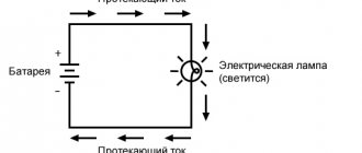
What is electric current and voltage
Electric current is the ordered movement of charged particles (electric charge carriers). The carriers of electric current are electrons (in metals and gases), cations and anions (in electrolytes), and holes in electron-hole conductivity. This phenomenon is manifested by the creation of a magnetic field, a change in the chemical composition or heating of the conductors. The main characteristics of the current are:
- The current strength, determined by Ohm's law and measured in Amperes (A), is denoted in formulas by the letter I;
- power, according to the Joule-Lenz law, measured in watts (W), is denoted by the letter P;
- frequency, measured in hertz (Hz).
Electric current, as an energy carrier, is used to obtain mechanical energy using electric motors, to obtain thermal energy in heating devices, electric welding and heaters, to excite electromagnetic waves of various frequencies, to create a magnetic field in electromagnets and to obtain light energy in lighting devices and various types of lamps .
Voltage is the work done by an electric field to move a charge of 1 coulomb (C) from one point on a conductor to another. Based on this definition, it is still difficult to understand what tension is.
In order for charged particles to move from one pole to another, it is necessary to create a potential difference between these poles (this is what is called voltage). The unit of measurement for voltage is the volt (V).
For a final understanding of the definition of electric current and voltage, an interesting analogy can be given: imagine that the electric charge is water, then the pressure of the water in the column is the voltage, and the speed of water flow in the pipe is the strength of the electric current. The higher the voltage, the greater the electric current.
What is alternating current
If you change the polarity of the potentials, the direction of flow of electric current changes. It is this current that is called alternating. The number of changes in direction over a certain period of time is called frequency and is measured, as mentioned above, in hertz (Hz). For example, in a standard electrical network in our country, the frequency is 50 Hz, that is, the direction of current movement changes 50 times per second.
What is direct current
When the ordered movement of charged particles always has only one direction, then such a current is called constant. Direct current occurs in a constant voltage network when the polarity of charges on one side and the other is constant over time. It is very often used in various electronic devices and technology when energy transfer over long distances is not required.
It will be interesting➡ What is an RCD?
General concept
Electric voltage is defined as the ratio of the work done by the field to transfer a test charge from one given point to another to the size of the potential. When a unit reserve is dislocated, work is performed that is equal to the voltage in the desired area. The total power is obtained by multiplying the work of the electric field for a unit charge by the number of potentials per specific unit of time.
In an alternating electrical circuit, 3 types of power are distinguished:
- active P;
- reactive Q;
- full type S.
In an alternating electricity circuit, the formula for calculating direct current is used only to calculate instantaneous power. This indicator undergoes changes over time and has almost no practical meaning for all other calculations. The power average requires time integration. The instantaneous power is combined over a certain period to calculate the magnitude in the line with periodic changes in the alternating flux strength and sinusoidal voltage.
The concept of complex numbers is used to relate all three types of power. This concept means that in an alternating circuit the load is expressed by a similar number so that the active variety appears to be a real component. The reactive indicator is an imaginary indicator, and the total power is shown in modulus form. These calculations take into account the phase angle φ, which is an argument for the power balance in the AC circuit.
Active power
The active conversion rate is also expressed through the mutual ratio of the flow force, voltage to the value of the active component of the resistance. In the line of sinusoidal and non-sinusoidal movement of electrons, the active load is equal to the sum of similar values in individual sections.
To determine the average periodic size, the active power of alternating current is used, the calculation formula P = U. I. cos φ (cosine), where:
- U is power.
- I is the flow force.
- φ is the phase shift angle.
The average instantaneous conversion rate in a single-phase circuit is taken as the rms value of current and voltage with a certain shift angle. In non-sinusoidal electricity circuits, power is equal to the sum of the corresponding indicators of individual movements. With the help of active power, the intensity of the irreversible modification of electricity into other types, for example, electromagnetic or thermal, is characterized.
The passing power is used as active power in the concept of long highways for the analysis of electromagnetic currents, the length of which is compared with the dimension of the wave. The required value is calculated as the difference between the decreasing and reflected powers. The resulting indicators of negative or positive load of the active type depend on the properties of the angular displacement coefficient.
Reactive characteristic
For designation, the additional unit volt-ampere reactive (var) is used. Russian analogues use var, and international experts use var. In the Russian Federation, the unit is allowed for electrical calculations in the form of a non-system value.
Finding is done using the formula P = U. I. sin φ (sine), where:
- U - rms power.
- I is the mean square flow force.
- φ - phase displacement angle, sine values are determined from tables.
When the indicator ranges from 0 to 90º (the current lags behind the voltage, and the load is active-inductive), the sine φ will have a positive value. With an angular shift from 0 to -90º (the electron flow is ahead of the load, the power has an active-capacitive property), the constant always shows a negative sign. Reactive power characterizes the tension that arises in electromechanical devices and circuits when energy field waves change in the main line of alternating sinusoidal flow.
In a physical sense, a reactive load shows the energy that is pumped from a current source to capacitors, inductors, motor windings, and subsequently returns to the source in one oscillatory period. Reactive power does not take part in the operation of electric current. In the case of a positive characteristic, the device consumes, and a load with a negative sign indicates energy production.
This circumstance is considered in a conditional context, since almost all energy-consuming devices, for example, asynchronous motors, as well as the payload supplied through a transformer, are of the active-inductive type. Synchronous motors in power plants simultaneously produce and consume energy depending on the maximum value of the excitation current in the rotor windings. This feature is used to coordinate the load level in a backbone in electrical engineering.
With the help of modern converters, reactive load compensation is performed to avoid overloads and to increase the power factor of electrical installations. The instruments more accurately estimate the amount of energy that flows in the opposite direction from the inductor to the AC source.
Full load
The indicator is used in physics to describe the power consumption that is applied to the supply units of the electrical network using resistors. The parameters of the EMF of distribution boards, cables, wires, power lines, and transformers are summed up.
The total load can be calculated using the formula S = U. I, where:
- S is the full load parameter (V/a).
- U is the design load in the generator.
- I is a complex indicator of current strength in combination with the winding value.
The conversion rate parameter depends on the characteristics of the applied current, and not on the properties of the load actually used. For this reason, the total power of electrical distribution panels and transformer units is measured in volt-amperes, and the value of watts does not apply to it.
History of the discovery of alternating current
For the first time, alternating currents began to receive attention due to their commercial value after the inventions created by Nikola Tesla. The material conflict with Edison marked the fate of both. When the American entrepreneur took back his promises to Nikola Tesla, he lost considerable benefits. The outstanding scientist did not like the free treatment; the Serb invented an industrial-type AC motor (he made the invention much earlier). Enterprises used exclusively constant. Edison promoted the said species.
Tesla was the first to show that much greater results can be achieved with alternating voltage. Especially when energy has to be transmitted over long distances. The use of transformers can easily increase the voltage, sharply reducing losses on active resistance. The receiving side returns the parameters to the original ones. Save a lot on the thickness of the wires.
Today it has been shown that direct current transmission is more economically profitable. Tesla changed the course of history. If scientists had come up with DC-DC converters, the world would look different.
Nikola Tesla started the active use of alternating current by creating a two-phase motor. Experiences in transmitting energy over considerable distances have put the facts in their place: it is inconvenient to transfer production to the Niagara Falls area, it is much easier to lay a line to its destination.
School version of the interpretation of alternating and direct current
Alternating current exhibits a number of properties that distinguish the phenomenon from direct current. First, let us turn to the history of the discovery of the phenomenon. Otto von Guericke is considered the founder of alternating current in human use. He was the first to notice: natural charges have two signs. Current can flow in different directions. Regarding Tesla, the engineer was more interested in the practical part; the author’s lectures mention two experimenters of British origin:
- William Spottiswoode is deprived of a Russian-language Wikipedia page, the national part is silent about work with alternating current. Like Georg Ohm, the scientist is a talented mathematician; it remains to be regretted that it is difficult to find out what exactly the husband of science did.
- James Edward Henry Gordon is much closer to the practical part of the question of the use of electricity. He experimented a lot with generators and developed a device of his own design with a power of 350 kW. He paid a lot of attention to lighting and energy supply to plants and factories.
It is believed that the first alternating current generators were created in the 30s of the 19th century. Michael Faraday studied magnetic fields experimentally. The experiments aroused the jealousy of Sir Humphry Davy, who criticized the student for plagiarism. It is difficult for descendants to find out what is right, the fact remains: alternating current existed unclaimed for half a century. In the first half of the 19th century, the electric motor was invented (by Michael Faraday). Worked powered by direct current.
Nikola Tesla was the first to realize Arago's theory of a rotating magnetic field. Two phases of alternating current (90 degree shift) were required. Along the way, Tesla noted: more complex configurations are possible (text of the patent). Later, the inventor of the three-phase motor, Dolivo-Dobrovolsky, tried in vain to patent the brainchild of a fertile mind.
For a long time, alternating current remained unclaimed. Edison opposed the introduction of the phenomenon into everyday life. The industrialist was afraid of large financial losses.
Nikola Tesla studied electric machines