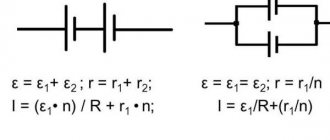
The quantity characterizing the amount of energy losses that occur when current flows through its source is defined as the internal resistance of the current source. Like regular resistance, it has a unit of measurement equal to 1 ohm. The current, moving through the source, loses part of its energy, which turns into heat, just like at any load resistance. This means that the voltage value at the source terminals depends on the current value, and not on the EMF.
Dependence of the voltage between its terminals on the source current
If we consider a closed electrical circuit that includes a current source (battery, accumulator or generator) and a load R, then the current flows inside the source. The internal resistance of the source, denoted by the letter r, prevents it.
For a generator, r is the internal resistance of the stator windings; for a battery, it is the resistance of the electrolyte.
Measurement of phase-zero loop resistance
A “phase-zero” loop is an alternating current electrical circuit that can result from a short circuit between the wires: “phase” and “zero” or “phase” and “phase”. Destruction of insulation, mechanical damage or accidental connection of exposed cable sections to each other can cause this. In installations with a solidly grounded neutral, the neutral conductor is physically connected to the neutral of the transformer; it is connected to the ground loop. When there is a short circuit to the housing or the phases are connected to each other, a circuit (loop) is formed.
The main task of the measurements taken is to find out what the magnitude of the current through the loop will be during a short circuit. This is mandatory for the calculation and selection of protective equipment. A good result will be a low loop resistance, then the current Ik.c. will be the greatest. Its value determines how quickly the protective circuit breaker will operate.
The less time spent disconnecting a damaged or shorted circuit, the greater the chance of preventing a cable fire. If a person gets an electric shock due to touch or short circuit, automatic voltage relief will save his life.
Enterprises annually carry out a set of measurements of protective grounding and phase-zero loop resistance. If the results are unsatisfactory, a number of measures are taken:
- sections of the wire that do not meet the requirements for cross-sectional diameter are replaced;
- bolted connections are twisted with the obligatory installation of mortise washers;
- the protective grounding contours are opened and inspected for the integrity of welded joints and the condition of the grounding elements;
- if necessary, additional elements are added to the protective grounding loop;
- serial connection of device housings to a common ground bus is eliminated.
After completing a set of measures, measurements are repeated.
Checking the resistance of the phase-zero loop
Comparison with potential difference
Electromotive force and potential difference in a circuit are very similar physical quantities, since both are measured in volts and are determined by the work done to move a charge. One of the main semantic differences is that e. d.s. (E) is caused by converting some energy into electrical energy, while potential difference (U) converts electrical energy into other forms. Other differences look like this:
- E transfers energy to the entire circuit. U is a measure of the energy between two points on a diagram.
- E causes U, but not vice versa.
- E is induced in electric, magnetic and gravitational fields.
- Concept e. d.s. is applicable only to the electric field, while potential difference is applicable to magnetic, gravitational and electric fields.
You might be interested in this Composition and definition of a capacitor: list of properties and markings
The voltage at the power supply terminals is usually different from the source emf. This occurs due to the presence of internal resistance of the source (electrolyte and electrodes, generator windings). The formula connecting the potential difference and the emf of the current source looks like U=E-Ir. In this expression:
- U is the voltage at the source terminals;
- r is the internal resistance of the source;
- I is the current in the circuit.
From this formula for electromotive force it follows that e. d.s. equal to the voltage when no current flows in the circuit. An ideal EMF source creates a potential difference regardless of the load (flowing current) and has no internal resistance.
In nature, there cannot be a source with infinite power when shorted across the terminals, just like a material with infinite conductivity. The ideal source is used as an abstract mathematical model.
Finding internal resistance
Current resistance: formula
It can be found in two ways: calculated or measured. The first path is taken when working with electrical circuits, the second is chosen when working with real devices.
A simple calculation is made using the Ohm's Law formula for a section of a complete circuit:
I = ε / (r + R).
To find out the current strength, you need to divide the EMF voltage by the sum of the resistances.
Expressing r from here, we get the formula for calculating it:
r = (ε / I) – R,
Where:
- r – internal resistance of the source;
- ε – source emf;
- I – current strength in the complete circuit;
- R is the resistance in the complete circuit.
The complex of measurements of this parameter for this device does not imply direct measurements. The voltages across the load resistance are tested in two current modes: no-load and short-circuit.
Since not any source can withstand even a short-term short circuit, a measurement method without calculations is taken.
The circuit includes an external load resistance in the form of a trimming resistor Rн. The value is set at which the voltage drop across the resistor would be equal to 1/2 U no-load. Then Rн measured by an ohmmeter will correspond to the internal resistance of the source.
Internal resistance of the current source
Definition and physical meaning
Applying some potential difference between the two ends of a conductor will create a flow of electrons from one end to the other. But this is not enough to maintain the flow of charges in the conductor. The drift of electrons leads to a decrease in the potential until it balances (the current stops). Thus, to create a direct current, mechanisms are needed that continuously return the described system to its original configuration, that is, preventing the aggregation of charges as a result of their movement. For this purpose, special devices called power supplies are used.
To illustrate their operation, it is convenient to consider a closed loop of resistance and a galvanic power source (battery). If we assume that there is no current inside the battery, then the described problem of combining charges remains unresolved. But in a circuit with a real power source, electrons are constantly moving. This occurs due to the fact that the flow of ions also flows inside the battery from the negative electrode to the positive one. The energy source that moves these charges in the battery is chemical reactions. This energy is called electromotive force.
EMF is a characteristic of any energy source capable of controlling the movement of electrical charges in a circuit. In analogy with a closed hydraulic circuit, the work of the energy source. d.s. corresponds to the operation of the pump to create water pressure. Therefore, the symbol representing these devices is indistinguishable on hydraulic and electrical diagrams.
Despite the name, electromotive force is not actually a force and is measured in volts. Its numerical value is equal to the work done to move a charge along a closed circuit. The source emf is expressed by the formula E=A/q , in which:
- E—electromotive force in volts;
- A is the work of external forces to move the charge in joules;
- q is the displaced charge in coulombs.
From this EMF formula it follows that the electromotive force is not a property of the circuit or load, but is the ability of the electricity generator to separate charges.
Reactive internal resistance
Impedance
In addition to galvanic and electrolytic two-terminal networks, there are power supplies whose circuits include reactive elements. When determining their internal resistance, the complex amplitude method is used. It involves using the complex resistances of the elements included in the circuit in calculations. The values of currents and voltages are replaced by the values of their complex amplitudes. The calculation algorithm itself is the same as when calculating active resistance.
The process of measuring r-reactance is slightly different from measuring the active component of resistance. The methods depend on what parameters of this complex function need to be learned: individual components or a complex number.
These parameters are affected by frequency, therefore, in order to obtain information about the internal reactive value r during testing, it is necessary to remove the frequency dependence. This is achieved by a set of measurements over the entire frequency range generated by such a two-terminal network.
High internal resistance
Piezoelectric sensors, condenser microphones, and other pulse sources have increased internal impedance. To effectively use such devices, you need to properly match the signal reading circuit. If coordination fails, losses are inevitable.
Important! Successful voltage matching is obtained when using a device with a higher input impedance than that of the signal source to pick up a signal. In the case of a high-impedance source, a buffer amplifier is used to read the signal.
Two-terminal network and its equivalent circuit
A two-terminal network is an electrical circuit containing two points of connection to other circuits. There are two types of electrical circuits:
- circuits containing a source of current or voltage;
- bipolar networks that are not sources.
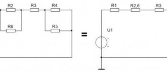
The first are characterized by electrical parameters: current, voltage and impedance. To calculate the parameters of such two-terminal networks, real circuit elements are first replaced with ideal elements. The combination that results from such a replacement is called an equivalent circuit.
Attention! When working with complex electrical circuits, taking into account the fact that the device operates at the same frequency, it is permissible to convert serial and parallel branches to obtain a simple circuit available for calculating parameters.
The second type of two-terminal circuits can be characterized only by the value of internal resistance.
From electrostatics to electrokinetics
Between the end of the 18th and the beginning of the 19th century, the work of scientists such as Coulomb, Lagrange and Poisson laid the mathematical foundations for the determination of electrostatic quantities. Progress in the understanding of electricity at this historical stage is obvious. Franklin had already introduced the concept of “amount of electrical substance,” but so far neither he nor his successors have been able to measure it.
Following Galvani's experiments, Volta tried to find evidence that the animal's "galvanic fluids" were of the same nature as static electricity. In his search for truth, he discovered that when two electrodes of different metals come into contact through an electrolyte, both become charged and remain charged despite the circuit being closed by the load. This phenomenon did not correspond to existing ideas about electricity because electrostatic charges in such a case had to recombine.
Volta introduced a new definition of the force acting in the direction of separating charges and maintaining them in this state. He called it electromotive. Such an explanation for the description of battery operation did not fit into the theoretical foundations of physics at that time. In the Coulomb paradigm of the first third of the 19th century. d.s. Volta was determined by the ability of some bodies to generate electricity in others.
Ohm made the most important contribution to the explanation of the operation of electrical circuits. The results of a series of experiments led him to the construction of the theory of electrical conductivity. He introduced the quantity “voltage” and defined it as the potential difference across the contacts. Like Fourier, who in his theory distinguished between the amount of heat and temperature in heat transfer, Ohm created a model by analogy relating the amount of charge transferred, voltage and electrical conductivity. Ohm's law did not contradict the accumulated knowledge of electrostatic electricity.
You might be interested in: Purpose, characteristics and operating principle of a varistor
Then, thanks to Maxwell and Faraday, explanatory models of current received a new field theory. This allowed the development of a field-related energy concept for both static potentials and electromotive force. The main dates for the evolution of the concept of EMF:
- 1800 - creation of the Voltaic galvanic battery;
- 1826 - Ohm formulates his law for a complete chain;
- 1831 - discovery of electromagnetic induction by Faraday.
The influence of internal resistance on the properties of a two-terminal network
The higher it is, the less power the source produces when a load is connected. The power in the load can be determined using the formula:
PR = E2/(r+R)2*R,
Where:
- E – EMF voltage;
- R – load resistance;
- r – active internal resistance of a two-terminal network.
The formula is applicable to two-terminal networks that do not release energy.
For your information. When the internal resistance of the two-terminal network approaches the load resistance, the power transfer reaches a maximum.
Source discharge capacity
The value depending on the strength of the discharge current is called the discharge capacity of the source. This is an electric charge that the source gives off during operation depending on the load current. This value can be considered constant conditionally. Thus, a starter battery with a discharge capacity C = 55 A*h will work for 10 hours at a discharge current of 5.5 A. When starting a cold or malfunctioning vehicle, the battery can be discharged in a few minutes.
In order to find the residual discharge capacity, charge-discharge cycles are performed. They are performed using load resistors. The discharge to the load resistance is carried out to the minimum permissible values of the electrolyte density. In this case, the operating time under load is measured. This is relevant during seasonal maintenance of batteries to identify self-discharge processes.
Car battery discharge capacity
The internal resistance of current sources is an important quantity. The methods used to reduce it are direct ways to increase the output power of the source, which means increasing the productivity of two-terminal networks. Correct measurement and calculation of the impedance of equivalent circuits allows us to bring the two-terminal network closer to the ideal source.
1.04. Current and voltage sources
ELECTRONICS BASICS
Voltage, Current and Resistance
Subsections: 1.01 1.02 1.03 1.04 1.05 1.06
The ideal voltage source is a “black box” that has two terminals between which it maintains a constant voltage drop, regardless of the value of the load resistance. This means, for example, that it should produce a current equal to I = UR if a resistor of resistance R is connected to the terminals. A real voltage source cannot produce a current greater than a certain maximum value, and in general it behaves like an ideal voltage source , to which a resistor with a small resistance is connected in series. Obviously, the lower the resistance of this series resistor, the better. For example, a standard 9V alkaline battery in series with a 3 ohm resistor behaves as an ideal 9V source and produces a maximum current (when short circuited) of 3A (which, unfortunately, will destroy the battery in a few minutes). ). For obvious reasons, the voltage source “prefers” the load in the form of an open circuit, but “dislikes” the load in the form of a closed circuit. (The concepts of “open circuit” and “closed circuit” are obvious: nothing is connected to an open circuit, and in a closed circuit a piece of wire closes the output.) The symbols for voltage sources are shown in Fig. 1.7.
Rice. 1.7.
The ideal current source is a “black box” that has two terminals and maintains a constant current in the external circuit, regardless of the value of the load resistance and the applied voltage. In order to perform its functions, it must be able to maintain the required voltage between its terminals. Real current sources (the least favorite topic in most textbooks) have a limited range over which the voltage they produce can vary (this is called the operating range of the output voltage, or simply the range), and, in addition, the output current of the source cannot be considered absolutely constant. The current source “prefers” a load in the form of a closed circuit, but “dislikes” a load in the form of an open circuit. Symbols of the current source are shown in Fig. 1.8.
Rice. 1.8.
A good example of a voltage source is a battery (a similar analogy cannot be found for a current source). For example, a standard flashlight battery provides a voltage of 1.5 V, an equivalent series resistance of 1/4 ohm, and a total energy capacity of approximately 10,000 watts (these characteristics gradually deteriorate; towards the end of the battery's life, the voltage may be about 1 V, and the internal resistance is several ohms). You'll learn how to create a better performing voltage source when we look at feedback. Electronic devices, with the exception of portable ones, rarely use batteries. In ch. 14 we will look at the interesting topic of designing low-power (battery-powered) circuits.
Subsections: 1.01 1.02 1.03 1.04 1.05 1.06
Signals