Content
- 1. General part
- 2. Initial data for calculation
- 3. Calculation of element resistances
- 4. Calculation of three-phase short circuit currents at point K1
- 5. Calculation of three-phase short circuit currents at point K2
- 5.1 For the middle position of the on-load tap-changer regulator of transformer T3
- 5.2 For the minimum position of the on-load tap-changer regulator of transformer T3
- 5.3 For the maximum position of the on-load tap-changer regulator of transformer T3
- 6. Calculation of three-phase short circuit currents at point K3
- 6.1 Resistance on the busbars of a 6 kV closed switchgear with the on-load tap-changer of transformer T3 set to the middle position
- 6.2 Resistance on the busbars of a 6 kV closed switchgear with the on-load tap-changer of transformer T3 set to the negative position
- 6.3 Resistance on the busbars of a 6 kV closed switchgear with the on-load tap-changer of transformer T3 set to the positive position
- 7. Calculation of short circuit current performed in Excel
- 8. References
The essence of the process
When any electrical device is connected to the circuit, the line shorts. An electric current begins to pass through it. It flows from the power source through the load (consumer) and returns. The current strength is determined by the load resistance of the elements connected to the circuit. If R is large, the magnitude of the current is small. Otherwise, it can reach large values. A situation in which an electrical connection occurs between the positive and negative contacts of an electrical line is called a short circuit.
For example, you can imagine a simple circuit consisting of a current source and an incandescent lamp. In order for it to light up, one of the source terminals (phase) should be connected to one of the lamp electrodes, and the other to the second contact of the lighting device (zero). A current will appear in a closed circuit, which, passing through the tungsten conductor of the lamp, will lead to its heating and emission of light. This type of work is called regular or normal work.
But if for some reason there is an additional contact between the terminals of the power source, and its resistance is negligible, almost all of the generated current will flow through it. The supply phase will be shunted to zero. As a result, all the voltage will be applied to the terminals of the generating device. And the current strength generated in the circuit will be determined only by the internal resistance of the power source.
The current strength will increase sharply. Taking into account the Joule-Lenz law, which determines the thermal effect of electric current, the heating of the electrical circuit will increase. If the current strength during a short circuit increases by 2 times, the generated heat will increase by 40 times. The phenomenon is often accompanied by wire melting and fire. This is why it is so important to be able to calculate short circuit currents for 110 V, 220 V or 380 V. These are the voltages that are used in everyday life and industry, ensuring the operation of electrical appliances and installations.
The following types of short circuit are distinguished:
- single-phase - establishing contact between the phase line and the zero line;
- two-phase - phase closure between each other or their common connection to the ground;
- three-phase - observed in 380 volt networks when three phases are connected.
It should be noted that a short circuit will occur only if the connection has the least resistance in the closed section of the circuit than that provided for in normal operation. It is determined in accordance with GOST and the rules for electrical installations (PUE).
a common part
It is required to calculate the three-phase short circuit current (SSC) on the buses of the designed indoor switchgear-6 kV substation 110/6 kV "GPP-3". This substation is powered by two 110 kV overhead lines from the 110 kV GPP-2 substation. The ZRU-6 kV “P4SR” receives power from two power transformers TDN-16000/110-U1, which operate separately. When one of the inputs is disconnected, it is possible to supply power to the de-energized bus section via a section switch in automatic mode (ATS).
Figure 1 shows the design diagram of the network
Figure 1 – Network design diagram
Since the chain from I N.S. "GPP-2" to I northern latitude. “GLP-3” is identical to chain II s.sh. from "GPP-2" to II northern latitude. "GPP-3" calculation is carried out only for the first chain.
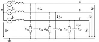
The equivalent circuit for calculating short-circuit currents is shown in Figure 2.
Figure 2 – Network equivalent circuit
The calculation will be made in named units.
General provisions
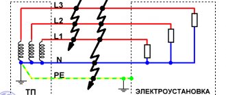
This technique is intended for measuring the impedance of a phase-to-zero circuit and measuring short-circuit current when testing electrical installations of buildings and structures in order to assess the operation of automatic power off when the insulation is damaged to prevent the occurrence of touch voltage in accordance with the standards by electrical laboratory employees. A protective device designed to automatically turn off the power to a circuit or electrical equipment must provide protection against indirect contact when a live part is shorted to an exposed conductive part or protective conductor of the circuit or electrical equipment in such a way that the power off time must ensure the electrical safety of a person while touching the conductive parts, also in case of a possible increase in the touch voltage values of 50 V AC (rms value) and 120 V rectified current. The shutdown time, regardless of the touch voltage value, for distribution circuits should not exceed 5 seconds. The longest shutdown time for a TN system with a rated voltage of 220 V should not exceed 0.4 seconds. The total resistance of the phase-zero circuit must satisfy the condition: Zs ? Un/Iк, where Zs is the total resistance of the phase-to-zero circuit; Un — rated voltage between phase and ground; Ik is the rated short circuit current that causes the protective device to trip. The total resistance of the phase-zero circuit includes resistances: windings of the power transformer, phase wire, neutral working wire, contacts of automatic machines, starters, etc. Based on the measured impedance of the phase-zero loop, the single-phase short circuit current is determined. Using the time-current characteristic of the protective device, the response time of the protective device is determined from the value of this current obtained by calculation. The current must have a certain multiple in relation to the rated current of the fuse link or electromagnetic release of the circuit breaker in accordance with clause 1.7.79. and clause 7.3.139. PUE.
Initial data for calculation
- 1. System data: Is=22 kA;
- 2. VL data - 2xAS-240/32 (Data are given for one circuit AS-240/32, RD 153-34.0-20.527-98, Appendix 9):
- 2.1 Positive sequence inductive reactance - X1ud=0.405 (Ohm/km);
- 2.2 Capacitive conductivity - bsp = 2.81x10⁻⁶ (S/km);
- 2.3 Active resistance at +20 C per 100 km of line - R=R20C=0.12 (Ohm/km).
- 3. Transformer data (taken from GOST 12965-85):
- 3.1 TDN-16000/110-U1, Uin=115 kV, Unn=6.3 kV, on-load tap-changer ±9*1.78, Uk.inn-nn=10.5%;
- 4. Flexible conductor data: 3xAC-240/32, l=20 m. (To simplify the calculation, the resistance of the flexible conductor is not taken into account.)
- 5. Data of the current-limiting reactor - RBSDG-10-2x2500-0.2 (taken from GOST 14794-79):
- 5.1 Rated current of the reactor - Inom. = 2500 A;
- 5.2 Nominal power losses per reactor phase - ∆P= 32.1 kW;
- 5.3 Inductive reactance – X4=0.2 Ohm.
Why do you need to know the values of the short-circuit current and the resistance of the “Phase-zero” loop?
I have already said a lot of things in the article. But what good is it to us to know these parameters of the power grid?
Knowing the short-circuit current (or the resistance of the “Phase-zero” loop) and the load power allows us to correctly and optimally (in terms of safety/functionality/reliability/price ) select the main elements of the power system - protection devices and cable cross-sections. A little more detail below.
Safety
I have already spoken about this, but I will repeat it. Electrical networks must be safe in all areas and in all modes. For this, in addition to insulation, circuit breakers and devices controlled by differential current (RCD) are used. Together with protective grounding, these devices protect equipment from short circuits and overloads, and people from the danger of direct or indirect contact.
Functionality
Knowing the short-circuit current, you can issue a conclusion about the need to install a stabilizer, or replace the cable line with a new one. In addition, we can draw a conclusion about selectivity - can it be ensured at least partially?
Reliability
In case of high short-circuit current, it is necessary to use switches with high breaking capacity for reliable operation at the moment of short-circuit. In addition, high demands must be placed on the quality of installation and components.
Price
It’s clear here - fulfilling the previous points significantly affects the price of the entire electrical network.
Calculation of element resistances
3.1 System resistance (for voltage 115 kV):
3.2 Overhead line resistance (for voltage 115 kV):
where: n - Number of wires in one overhead line 110 kV overhead line;
3.3 Total resistance to the transformer (for voltage 115 kV):
X1.2=X1+X2=3.018+0.02025=3.038 (Ohm)
R1.2=R2=0.006 (Ohm)
3.4 Transformer resistance:
3.4.1 Transformer resistance (on-load tap-changer is in the middle position):
3.4.2 Active resistance of the transformer (on-load tap-changer is in the extreme “minus” position):
3.4.3 Active resistance of the transformer (on-load tap-changer is in the extreme “positive” position):
3.4.4 Inductive reactance of the transformer in the middle position of the on-load tap-changer:
Minimum inductive reactance of the transformer (on-load tap-changer is in the extreme “minus” position)
Where:
- half of the full (total) voltage regulation range on the high voltage side of the transformer.
Maximum inductive reactance of the transformer (on-load tap-changer is in the extreme “positive” position)
The value included in the formula above is the voltage corresponding to the extreme positive position of the on-load tap-changer, and it is equal to Umax.VN=115*(1+0.1602)=133.423 kV, which exceeds the highest operating voltage of electrical equipment equal to 126 kV (GOST 721-77 " Power supply systems, networks, sources, converters and receivers of electrical energy. Rated voltages over 1000 V"). The voltage UmaxVN corresponds to Uк%max=10.81 (GOST 12965-85).
If Umax.VN turns out to be greater than the maximum permissible for a given network (Table 5.1), then Umax.VN should be taken according to this table. The value of Uk% corresponding to this new maximum value of Umax.VN is determined either empirically or found from the appendices of GOST 12965-85.
3.4.5 Current-limiting reactor resistance (at voltage 6.3 kV):
X4=0.2 (Ohm)
What is the threat of short circuit?
A short circuit primarily poses a threat to human health and life. This is associated with a fire hazard: fire of wire insulation, ignition of surrounding objects, and the ability of the insulation to spread combustion. Also, a change in current strength can be detrimental to the devices and instruments used, leading to catastrophic consequences. A short circuit can cause economic loss. Therefore, it is important to use measures to prevent the occurrence of the phenomenon and resort to installing protection methods.
Calculation of three-phase short circuit currents at point K2
5.1 For the middle position of the on-load tap-changer regulator of transformer T3
5.1.1 Total resistance to point K2:
Х∑==Х1+Х2+Х3ср=3.018+0.02025+86.789=89.827 (Ohm) R∑=R2+К3=0.006+4.391=4.397 (Ohm)
5.1.2 Three-phase short circuit current:
5.1.3 The current at the short circuit, reduced to an effective voltage of 6.3 kV, is equal to:
5.1.4 Short circuit surge current:
5.2 For the minimum position of the on-load tap-changer regulator of transformer T3
5.2.1 The value of the total resistance at point K1 is reduced to a network voltage of 96.577 kV:
5.2.2 Three-phase short circuit current:
5.2.3 The current at the short circuit, reduced to an effective voltage of 6.3 kV, is equal to:
5.2.4 Short circuit surge current:
5.3 For the maximum position of the on-load tap-changer regulator of transformer T3
5.3.1 The value of the total resistance at point K1 is reduced to a network voltage of 126 kV:
5.3.2 Three-phase short circuit current:
5.3.3 The current at the short circuit, reduced to an effective voltage of 6.3 kV, is equal to:
5.3.4 Short circuit surge current:
Measurement method.
The proposed methods provide only approximate values of the phase-zero circuit impedance or short circuit currents, since they do not take into account the vector nature of the voltage, that is, the real conditions existing at the actual time of the ground fault. This degree of approximation is acceptable provided that the reactance of the circuit under test is negligible. Before measuring the resistance of the phase-zero circuit, it is recommended to test the resistance of the protective conductors, their continuity, as well as the insulation resistance of the electrical installation elements of the building.
Calculation of three-phase short circuit currents at point K3
6.1 Resistance on the busbars of a 6 kV closed switchgear with the on-load tap-changer of transformer T3 set to the middle position
6.1.1 The value of the total resistance at point K2 is reduced to a network voltage of 6.3 kV:
6.1.2 The current at the short circuit, reduced to an effective voltage of 6.3 kV, is equal to:
6.1.3 Short circuit surge current:
6.2 Resistance on the busbars of a 6 kV closed switchgear with the on-load tap-changer of transformer T3 set to the negative position
6.2.1 The value of the total resistance at point K2 is reduced to a network voltage of 6.3 kV:
6.2.2 The current at the short circuit, reduced to an effective voltage of 6.3 kV, is equal to:
6.2.3 Short circuit surge current:
6.3 Resistance on the busbars of a 6 kV closed switchgear with the on-load tap-changer of transformer T3 set to the positive position
6.3.1 The value of the total resistance at point K2 is reduced to a network voltage of 6.3 kV:
6.3.2 The current at the short circuit, reduced to an effective voltage of 6.3 kV, is equal to:
6.3.3 Short circuit surge current:
The calculation results are entered into table PP1.3
Table PP1.3 – Calculation data for three-phase short circuit currents
| Transformer on-load tap position | Short circuit currents | Short circuit point | ||
| K1 | K2 | K3 | ||
| On-load tap-changer in middle position | Short circuit current, kA | 21,855 | 13,471 | 7,739 |
| Short-circuit shock current, kA | 35,549 | 35,549 | 20,849 | |
| On-load tap-changer in minus position | Short circuit current, kA | — | 13,95 | 7,924 |
| Short-circuit shock current, kA | — | 36,6 | 21,325 | |
| On-load tap-changer in positive position | Short circuit current, kA | — | 13,12 | 7,625 |
| Short-circuit shock current, kA | — | 34,59 | 20,553 | |
2.1. Measurement procedure with the MZC-300, MZC-303E device
2.1.1 Conditions for performing measurements and obtaining correct results
To start measuring, several conditions must be met. The meter automatically disables the ability to begin measurements (this does not apply to line voltage measurements) if any of the following abnormal conditions are detected: Situation Displayed symbols and warning signals Explanations The voltage applied to the meter is greater than 250V. OFL inscription and long beep. Immediately disconnect the meter from the network under test! The integrity of the PE/N wire is broken. The _—_ symbol is displayed and a long beep sounds. The symbol and sound signal appear after pressing the [start] key. Precautions must be taken as the network under test does not have overcurrent protection! The voltage applied to the meter is too low to measure resistance - less than 180V. -U- is displayed and two long beeps sound. The inscription and sound signals appear after pressing the [start] key. Thermal protection blocks the measurement, which is possible with very intensive measurements. The T symbol appears on the display and two long beeps sound. The symbol and beeps appear after pressing the [start] key. During Auto Calibration, the sum of the circuit impedance and the test lead impedance is very large. Instead of the measurement result, the ]-[ symbol is displayed, the device additionally generates two long beeps. The meter also signals a situation in which the measurement result cannot be considered correct: ¦ If the batteries are discharged, the display shows the inscription bAt alternately with the voltage measurement result. The specified measurement can be made, but the results obtained cannot be the basis for a correct assessment of the electrical safety of the electrical installation under test.
2.1.2 Methods for connecting the meter
Fig.6. Measurement in working chain (LN)
Rice. 7. Measurement in the protective circuit (L-PE) a) TN network (with grounding) b) TT network (with protective grounding)
Rice. 8. Testing the effectiveness of protection of the electrical installation enclosure
The meter is connected to the circuit under test or to the device as shown in Fig. 6, 7 and 8. You should pay attention to the correct selection of measuring tips, since the accuracy of the measurements is highly dependent on the quality of the connections made. A good connection must be ensured and a large measuring current must be allowed to flow continuously. It is unacceptable, for example, to attach a crocodile clip to dirty or rusty elements - they must be thoroughly cleaned or pointed probes must be used for measurements.
2.1.3 AC voltage measurement
Devices of the MZC-300 family can measure AC voltage in the range 0...250V. The device measures the voltage between the measuring sockets L and PE/N. The input resistance of the voltmeter is at least 150 kOhm. The voltmeter mode switches on automatically after turning on the meter's power, and also approximately 5 seconds after: • Measuring the impedance, expected short-circuit current or test lead resistance (during Auto-calibration); • The last time you pressed any of the keys associated with displaying measurement results.
2.1.4 Measuring short-circuit loop parameters
The MZC-300 family of devices uses a method for measuring the impedance of a short-circuit loop by “artificially short-circuiting” the circuit under test through a resistor that limits the amount of measuring current. The voltage at the device sockets is measured immediately before the flow of the measuring current and during the flow of the measuring current, taking into account the vector structure of voltage and current. Next, the processor calculates the total resistance of the short circuit loop, identifies its active and reactive components, as well as the phase angle that will occur in the circuit under test in the event of a short circuit. The limiting resistor has a value of 10 Ohms, and the flow time of the measuring current is 30 ms. The meter independently selects the impedance measurement range. Displaying the measurement result as resistance or current The measurement result can be displayed as the short-circuit loop impedance or the expected short-circuit current. Pressing the Z/I key while one of these values is displayed switches the instrument to display the other. The device always measures the impedance, and the expected short-circuit current displayed on the display is calculated by the formula: where: Uo = 220V is the rated voltage of the network under study, Zs is the measured impedance. Therefore, in networks with a different rated voltage, it is necessary to make an appropriate correction when calculating the short-circuit current. For example, in a network with Uo = 230V, the expected short circuit current will be 230/220 = 1.045 times greater than that displayed on the device. In the following, the term "impedance measurement" will mean taking a measurement and displaying the result as current or resistance.
2.1.5 Performing a measurement and reading the result
The measurement process can be started by pressing the START key at the moment when the meter displays the voltage value on the display. If there is no reason to block the measurement, the device performs the measurement and, depending on the settings made by the User using the Z/I key, displays on the display the value of the impedance or the expected short-circuit current. The remaining components of the measurement result: active resistance, reactance and phase angle can be called up on the display by pressing the SEL key. After the device automatically returns to the voltage measurement mode, the measurement result remains available. It can be brought up again on the display using the SEL key. Impedance, active resistance and reactance are specified up to a value of 199.9 ohms. If in the resistance measurement mode, the readings are more than 199.9 Ohms, the OFL measurement range symbol will appear on the display, and in the short-circuit current mode, the meter will display a very low value symbol UFL. If impedance values of more than 199.9 Ohms are expected at the measurement point and such a result is acceptable for a given electrical installation, then the MZC-ZOZE device can use the RCD function, which increases the measurement range to 1999 Ohms. WARNING: Taking a large number of measurements in a short period of time can generate a lot of heat at the limiting resistor. As a result, the device body may become hot. This is normal. The meter has protection against overheating.
2.1.6 Ground resistance measurement
The MZC-300 family of meters can be used for rough ground resistance measurements. For these purposes, a phase conductor of the network is used as an additional voltage source, which allows creating a measuring current, as shown in Figure 9.
rice. 9. Connection method for measuring ground resistance
The measurement result is the sum of the resistances of the measured grounding conductor, working grounding, source and phase conductor. If the obtained result does not exceed the permissible value for the grounding being tested, then we can conclude that the grounding is performed correctly and there is no need to use more accurate measurement methods.
2.1.7 Safe working practices.
Work on measuring the impedance of the phase-zero loop and single-phase fault currents is carried out according to a permit or by order. The type of work registration is determined by the employee who has the right to issue orders and orders. Persons from electrical technical personnel at least 18 years of age, trained and certified in knowledge of safety regulations and this technique, provided with tools, personal protective equipment, and special clothing are allowed to work. The team must consist of at least two people: - a work supervisor with an electrical safety group of at least III; - a member of a team with an electrical safety group of at least III. When supplying voltage from an external power source, organizational and technical measures must be drawn up and carried out, both at the connection point and at the workplace. Connecting wires, power cable, step-down transformer must be double insulated. It is prohibited to perform work in high humidity, as well as in fire-, fire- and explosive environments and rooms. Based on the measurement results, a protocol of the established form is drawn up. Persons who have committed violations of safety regulations or PTEEP, as well as those who have distorted the reliability and accuracy of measurements, are liable in accordance with the legislation and regulations on the mobile electrical laboratory.
Short circuit current calculation performed in Excel
If you perform this calculation using a piece of paper and a calculator, it takes a lot of time, besides, you can make a mistake and the whole calculation will go down the drain, and if the source data is constantly changing, this all leads to an increase in design time and unnecessary waste of nerves.
Therefore, I decided to perform this calculation using an Excel spreadsheet, so as not to waste my time on TKZ recalculations and to protect myself from unnecessary errors; with its help, you can quickly recalculate short-circuit currents, changing only the original data.
I hope that this program will help you and you will spend less time designing your object.
How to prevent short circuit
There is a short answer to this question: to prevent a short circuit from occurring, follow the rules for operating electrical appliances. The specific recommendations below will help prevent short circuits.
Do not turn on partially damaged appliances
If the cable in an iron or refrigerator is frayed and the inner shell is visible, do not turn it on until you have repaired it. First, carefully remove the top layer of insulation in the damaged area and inspect the external condition of the insulation. Wrap all damage and cracks tightly with electrical tape. Then put the top shell back and rewind it too.
The plug often needs to be replaced, for example if it is very loose or the housing is damaged. It is sold in any transition or store, so don’t delay your purchase.
Damage can occur not only on the power cord, but also inside. For example, if you turn on something and hear sparking inside. This already indicates a serious malfunction, even if the electrical equipment works, at first glance, normally. In this case, unplug it from the outlet and take it to a service center (or repair it yourself).
Remember that turning on a faulty electrical appliance often leads to a short circuit, which will destroy all wiring in the house and is likely to cause a fire. If you remain nearby, you risk serious injury.
Even if you have checked all the wiring and turn on only new, working equipment, this does not provide a 100% guarantee that an accident will not occur in your network. Therefore, always install high-quality circuit breakers and RCDs in the panel.
We recommend reading: SMD reference book, SMD codes, marking of radio components
Use suitable circuit breakers
The recommendation primarily concerns household consumers: owners of apartments, houses, and dachas. Using so-called “bugs” instead of fuses, as well as installing unsuitable circuit breakers, increases the risk of cable heating and short circuits.
Example: the electricity supplier has agreed to install a 16A circuit breaker. This fuse is designed for the permitted power consumption and current. It trips when the current exceeds 16 amperes and protects the network from an accident. If you install a 40A “breaker” or “bug” in this network, the consumer will not suffer from frequent fuse trips. But the network will remain unprotected from abnormal loads. This increases the risk of cable damage and short circuits.
A “bug” is a homemade or self-modified fuse. Typically this is a fuse that uses a thick wire instead of a fuse.
Fuse with bug
Check cable functionality
Before installing wiring, check the cable for integrity of insulation and absence of short circuit. A cable with tape armor must be checked for a short to armor. This is easiest to do with a megohmmeter.
A megohmmeter will help identify a short circuit
Replace aluminum wiring with copper
With a smaller wire cross-section, copper conducts electricity better and can withstand greater loads. In addition, it withstands more mechanical bending and does not oxidize as quickly as aluminum.
New PUEs generally prohibit the installation of aluminum wiring in household networks, since it is potentially dangerous and less efficient in operation than copper.
In Soviet times, aluminum wiring was often used in residential buildings. If your apartment still enjoys such a “Soviet legacy”, think about it; its service life has probably expired long ago.
Don't ignore dust and moisture protection
When placing sockets, switches or electrical appliances in places of high humidity, take care of a high level of dust and moisture protection. For example, outdoors where precipitation, dew and fog are possible, it should be at least IP67. The minimum level for a bathroom is IP44, if there is a possibility of direct water splashes, then IP56 is better.
If water gets inside, the socket will begin to spark, the plastic casing will melt, and eventually a short circuit will occur. Therefore, always choose the optimal level of dust and moisture protection.
Do not operate electrical networks without grounding or zeroing.
Grounding and zeroing alone does not prevent a short circuit. But thanks to this protection, in the event of a short circuit, the current strength is instantly reduced to a level that is safe for humans and equipment.
In apartment buildings and private buildings, grounding is implemented so that in the event of a short circuit, circuit breakers are triggered. Therefore, it is enough for household consumers to use reliable fuses, as described above.
Choose a cable of sufficient cross-section
Before purchasing, be sure to calculate the likely maximum load on the line. The cross-section must be sufficient to safely pass current during peak load hours, for example, in winter when the heating is on or on weekends, when the maximum number of electrical consumers is working at home.
The optimal cross-section for socket groups is 2.5mm² and above, and for lighting 1.5mm² or 0.5mm² for LED. But it’s better to make accurate calculations of the maximum power and select the cross-section based on them.
Consider the electrical wiring diagram in the building and on the site during repairs
During repairs or excavation work on the site, it is important not to damage the wiring. Therefore, when drilling or tapping walls, it is important to check the area using a hidden wiring tester. And before carrying out excavation work, it is important to study the wiring diagram on the site.
Negative impact of short circuit for a person and his property
A short circuit, depending on the location of its occurrence, leads to detrimental consequences for property and the safety of human life. These include:
- burning and failure of electrical appliances;
- ignition of electrical wiring;
- a decrease in the voltage of the electrical network (in industrial conditions it leads to a shutdown of enterprises);
- decrease in the efficiency of power supply systems;
- the occurrence of electromagnetic influence leads to disruption of the functioning of communications located underground.
Calculation features
Calculation of currents of three-phase equipment is carried out using special formulas.
If the calculation of the three-phase short circuit current needs to be done for electrical networks with voltages up to 1000 V, then the following nuances must be taken into account when making calculations:
- A three-phase system should be considered symmetrical.
- The power supply of the transformer is taken as a constant value equal to its nominal value.
- The moment of occurrence of a short circuit is usually considered to be at the maximum current value.
- EMF of power sources located at a considerable distance from the section of the electrical network where the short circuit occurs.
Also, when calculating the short circuit parameters, it is necessary to correctly calculate the resulting conductor resistance, but this must be done by bringing a single power value.
If you calculate resistance using standard formulas known from a physics course, you can make mistakes due to the unequal rated voltage at the moment a short circuit occurs for different sections of the electrical circuit. The choice of such a base power allows you to significantly simplify calculations and significantly increase their accuracy.
When calculating the short-circuit current, it is also customary to select the voltage not based on the nominal value, but in excess of this indicator by 5%. For example, for a 380 V electrical network, the base voltage for calculating short circuit currents will be 0.4 kV.
For an AC network with a voltage of 220 V, the base voltage will be 231 V.
Who is involved in calculating the short circuit?
Short circuit calculations are carried out by qualified specialists who not only perform the necessary calculations, but are also responsible for the further operation of electrical equipment.
Home electricians can also carry out these calculations, but only if they have basic knowledge about the nature of electricity, the properties of conductors and the role of dielectrics in their reliable isolation from each other.
At the same time, the obtained result of the short circuit value, before carrying out electrical work, must be rechecked independently, or use the services of specialized companies that carry out these calculations on a paid basis.
How to calculate short-circuit current using special formulas will be described in detail below.
Short circuit protection
There are various devices for short circuit protection:
- circuit breakers;
- circuit breakers with automatic return to the on state;
- RCD;
- fuses;
- "traffic jams";
- self-resetting fuses.
The presented circuit involves a zener diode and diodes that protect the LEDs from the effects of reverse currents. 2 resistors are responsible for limiting the current in the protection system. The fuse must be of a self-resetting type; the ratings of the elements must be selected individually depending on the conditions.
An effective way to protect against this phenomenon is to use a current-limiting reactor. It is used in electrical circuit protection systems, where the magnitude of the short circuit can be of such a magnitude that conventional equipment cannot cope with.
The rector has the form of a coil with an inductive type resistance, connected to the network in a series circuit. Acceptable circuit operation allows the reactor voltage drop to be maintained at around 4%. When a short circuit occurs, the main part of the voltage is supplied to this device. Such equipment comes in oil and concrete types. Each of them is used depending on the type of electrical wiring and the equipment it powers.
Determination of circuit breaker resistances
We determine the active resistance of the contacts according to Appendix 4, Table 19 GOST 28249-93:
- for a switch for a current of 1000 A – rav1 = 0.12 mOhm;
- for a circuit breaker with a current of 200 A - rav2 = 0.60 mOhm.