TOE › Calculation of DC circuits
When calculating the operating mode of an electrical circuit, it is very often necessary to determine the currents, voltages and powers in all its sections for given EMF sources and resistances of the circuit sections. This calculation is based on the application of Kirchhoff's laws.
This article assumes that you are familiar with the definitions of node, branch, and loop.
Kirchhoff's first law
Kirchhoff's first law states that in the branches forming a node of an electrical circuit, the algebraic sum of currents is equal to zero (currents entering the node are considered positive, currents leaving the node are considered negative).
Using this law for node A (Figure 1), we can write the following expression:
Figure 1 - Kirchhoff's first law
I1 + I2 − I3 + I4 − I5 − I6 = 0.
Try to apply Kirchhoff's first law yourself to determine the current in a branch. The diagram above shows six branches forming an electrical node B , the currents of the branches enter and exit the node. One of the currents i is unknown.
#1. Write down the expression for node B
Wrong
Further
#2. Find the current i
Wrong
Complete
Ohm's law
Current, voltage, and resistance are directly related to Ohm's law, which describes the ratio of voltage (applied to an element) to a given resistance that causes current to flow.
| Remember that we always denote these values as follows: U is voltage, R is resistance, I is current. |
You will encounter this law very often in the field of electronics. Fortunately, you don't need to learn this law by heart, because... In its simplest form, it is expressed by three simple formulas, which for ease of use are usually written in the form of a triangle, as in the picture below:
| In fact, this is one pattern (template), transformed as needed. It is enough to remember one of the formulas (for example, U = I * R) to transform it into another at any time. |
Result
Great!
Try again(
Selecting the direction of currents
is unknown when calculating the circuit , then when drawing up equations according to Kirchhoff’s law, they must first be selected arbitrarily and indicated on the diagram with arrows. In reality, the direction of currents in the branches may differ from those arbitrarily chosen. Therefore, the selected current directions are called positive directions. If, as a result of the circuit calculation, any currents are expressed as negative numbers, then the actual directions of these currents are opposite to the selected positive directions.
For example
Figure 2
Figure 2a shows the electrical unit. Arbitrarily, we indicate the directions of the currents with arrows (Figure 2, b).
Important! When choosing the direction of currents in branches, two conditions must be met: 1. The current must flow from the node through one or more other branches; 2. At least one current must enter the node.
Let us assume that after calculating the circuit the following current values are obtained:
I1 = -5 A; I2 = -2 A; I3 = 3 A.
Since the current values I1 and I2 turned out to be negative, therefore, the directions of I1 and I2 are indeed opposite to those previously selected (Figure 3).
Figure 3 - the actual direction of the currents is indicated by blue arrows
- I1 − I2 + I3 = 0;
- -5 − (-2) +3 = 0;
- -I1 + I2 + I3 = 0;
- -5 + 2 +3 = 0.
Educational materials
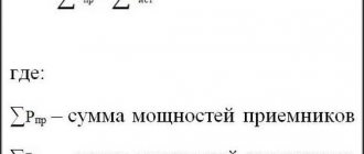
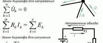
According to Kirchhoff's first law, the algebraic sum of the currents of the branches converging at a node is equal to zero:
According to Kirchhoff's second law, the algebraic sum of the voltages on the resistive elements of a closed circuit is equal to the algebraic sum of the emfs included in this circuit.
Get a decision on TOE
The calculation of a multi-circuit linear electrical circuit having “b” branches with active and passive elements and “y” nodes comes down to determining the currents of individual branches and voltages at the terminals of the elements included in this circuit.
A branch that does not contain an EMF source is called passive. The branch containing the EMF source is called active.
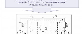
Kirchhoff's 1st law applies to independent nodes, i.e. those that differ from each other in at least one new branch, which allows us to obtain (y - I) equations.
The missing equations in the amount of b - (y - I) are composed based on Kirchhoff's second law. The equation is written for independent circuits that differ from one another in at least one branch.
Calculation procedure:
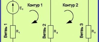
- identify branches, independent nodes and circuits in an electrical circuit;
- using arrows, they indicate arbitrarily chosen positive directions of currents in individual branches, and also indicate an arbitrarily chosen direction of bypassing the circuit;
- make up equations according to Kirchhoff’s laws, applying the following sign rule:
- currents directed to a circuit node are written with a “plus” sign, and currents directed from the node are recorded with a “minus” sign (for Kirchhoff’s first law);
- The EMF and voltage on the resistive element (RI) are taken with a plus sign if the directions of the EMF and current in the branch coincide with the direction of bypassing the circuit, and if in the opposite direction - with a minus sign;
Negative current values of any branch indicate that the previously selected arbitrary current directions turned out to be erroneous. This should be taken into account, for example, when constructing a potential diagram, where the true direction of the current must be known.
In Fig. 4, a shows the original electrical circuit, for which the currents in the branches should be calculated. The directions of currents and circuit bypass are shown in Fig. 4, b.
Fig.4
The system of equations compiled according to Kirchhoff’s first and second laws has the form
Next >Lectures on the basics of electrical engineering >
Interpretation of Ohm's law
As for current, Ohm's law says that it is directly proportional to voltage. For example, if we increase the voltage by 10 times, the current will also increase by 10 times. This can be seen from the formula I = U / R (the higher the voltage, the higher the current).
If you compare it with water, you can clearly see in the picture: when the water level rises (voltage increases), more water flows out of the dam (current increases).
I~U
As you can see, there is an increasing voltage (water level) with a constant resistance (position of the lock in the dam). Conclusion: increasing the voltage leads to more current flowing at the same resistance.
| I ~ U here means that the current is directly proportional to the voltage. |
Let's look at another example. This time the water level (voltage) will be constant. Only the degree of opening of the sluice gate in the dam (resistance) will change:
I~1/R
This time we can notice that at a constant voltage, the current flowing through a given element depends on its resistance. Conclusion: current is inversely proportional to resistance (the lower the resistance, the more current will flow in the circuit).
| The notation I ~ 1/R here means that the current is inversely proportional to the resistance. |
Let's apply Ohm's law in practice
Let's check in practice whether Ohm's law really works. Let's take a battery or accumulator with a voltage of about 9 volts. We need to find out how much current will flow if we close the circuit by connecting a 10 kΩ resistor to it. The circle with the inscription “mA” in the diagram indicates our multimeter (tester) configured to measure amperes.
First we check theoretically. To do this, we use the formulas we know:
U = 9 V, R = 10 kOhm, I =?
I = U / R = 9 V / 10000 Ohm = 0.0009 A = 0.9 mA
This means the tester should show us about 0.9 mA. Now assemble this circuit on a breadboard . In case of problems you can use the example below. Just be careful not to short circuit the circuit when installing components; shorting can damage the battery.
| Don't forget to set your multimeter correctly when measuring current! |
The measurement result in the above circuit is 0.95 mA. Why did we get one figure according to calculations, but in practice, after measuring with a tester, we got another? Please remember that measurements are subject to error. As you remember from the previous article, all resistors have an error of about 5%, as well as the resistance of the probes and the multimeter itself, and besides, the battery or accumulator may not be infected at all 9V! On average, it turns out that the result is correct!
Now, for the test, we need to check what will happen if we connect another resistor, namely 1 kOhm, instead of the 10 kOhm resistor. Keeping Ohm's law in mind, we should already be able to predict that connecting a resistor with 10 times less resistance should produce 10 times more current. Let's check:
Read also: Reference voltage sources
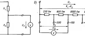
What is a voltage divider?
A voltage divider is nothing more than one of the practical applications of the above laws. In practice, everything is very simple - we connect two resistors in series and power them.
The voltage on the legs of each of them will be proportionally less, but their sum will be equal to the supply voltage. This is nothing more than an illustration of the operation of Kirchhoff's second law. In other words, this system allows us to split the supply voltage , so that we can get, for example, 6V from a 9V battery.
Read also: What is FPGA?
This is described by the following formula:
Uinput is the voltage feeding our divider. The numerator is the value of the resistor across which we want to find out the voltage drop. The denominator is the sum of both resistances. We have already made this connection, so we will not repeat it now - the most important thing is to remember the formula that allows you to calculate the voltage that should appear on the resistor.
For example, let's calculate the voltage value that we get from a divider consisting of 1 kOhm and 220 Ohm resistors, powered by 3 V. The circuit will look like this:
In this case, the calculation of the voltage Uoutput will look like this:
Now do your own calculations for a voltage divider consisting of 1k and 330 ohm resistors powered by a 9V battery. Calculate Uoutput across the 1k ohm resistor. Build such a circuit yourself on a breadboard and measure the voltage. If you have problems, go back to the example above.
What is internal resistance?
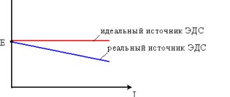
Internal resistance is a parameter that is common to every power supply, but it is often forgotten. Any real voltage source can, in the simplest case, be modeled as a series combination of an ideal source and a certain resistance.
| The easiest way to imagine is a battery or accumulator with a resistor inside. |
Nobody needs such resistance, but nothing can be done about it; manufacturers can only try to keep this resistance as low as possible. This is due to the composition of contact resistances, battery covers, leads, etc. In addition, resistance may depend on temperature, life of the elements and other factors.
This resistance cannot be accurately calculated by yourself and do not try to measure it with a multimeter! Only the battery manufacturer can provide this information. Fortunately, this is not important for us now; the most important thing is simply to know about the existence of internal resistance.
The presence of internal resistance is illustrated by a very simple experiment. Let's measure the voltage in the circuit, with and without current flowing through 1 kOhm and 10 kOhm resistors. Here is a very simple measurement scheme:
Measurement examples:
| 1k resistor connected | 10 kOhm resistor connected | Without resistor |
As you can see in the example above, by increasing the current from the battery we get a lower voltage. This can be perfectly explained as follows: the smaller R1 (which represents the load) compared to R2 (which represents the internal resistance), the more voltage is applied to R2. For many, measuring without a resistor can be confusing because they think it means there is no resistance - this is incorrect thinking.
| The absence of a resistor should be understood as an infinitely large resistance. Since no current flows in the circuit and the battery is not loaded in any way, the measured voltage is the highest. |
Remember that if you charge the battery with too much current (through a low resistance resistor), the battery may heat up and fail (electrolyte may leak)! When drawing high current, use a source with sufficiently low internal resistance and sufficiently high power.
| The above phenomenon bothers many newbies trying to power their projects with small batteries (eg 9V). They forget that high current consumption (eg from motors) causes a voltage drop across the battery. This may interfere with the operation of the entire system. |