§101. Current and voltage measurement
Current measurement.
To measure the current in the circuit, ammeter 2 (Fig. 332, a) or milliammeter is connected to the electrical circuit in series with receiver 3 of electrical energy.
To ensure that turning on the ammeter does not affect the operation of electrical installations and does not create large energy losses, ammeters are made with low internal resistance. Therefore, practically its resistance can be considered equal to zero and the voltage drop it causes can be neglected.
The ammeter can only be connected in series with the load. If the ammeter is connected directly to source 1, then a very large current will flow through the coil of the device (the resistance of the ammeter is low) and it will burn out.
Rice. 332. Circuits for measuring current (a, b) and voltage (c, d)
To expand the measurement limits of ammeters intended for operation in DC circuits, they are included in the circuit parallel to shunt 4 (Fig. 332,b). In this case, only part IA of the measured current I passes through the device, inversely proportional to its resistance RA. Most of this current passes through the shunt.
The device measures the voltage drop across the shunt, which depends on the current passing through the shunt, i.e. it is used as a millivoltmeter. The instrument scale is graduated in amperes. Knowing the resistance of the device RA and the shunt Rsh, it is possible to determine the measured current from the current IA recorded by the device:
I = IA (RA+Rsh)/Rsh = IАn (105)
where n = I/IA = (RA + Rsh)/Rsh is the shunt coefficient. It is usually chosen to be equal to or a multiple of 10. The shunt resistance required to measure a current I n times greater than the device current IA is
Rsh = RA/(n-1) (106)
Structurally, shunts are either mounted in the device body (shunts for currents up to 50 A), or installed outside it and connected to the device with wires.
If the device is intended for constant operation with a shunt, then its scale is calibrated immediately in the values of the measured current, taking into account the shunt coefficient, and no calculations are required to determine the current. In the case of using external (separate from devices) shunts, they are indicated by the rated current for which they are designed and the rated voltage at the terminals (calibrated shunts).
According to standards, this voltage can be 45, 75, 100 and 150 mV. Shunts are selected for devices so that at the rated voltage at the shunt terminals, the device needle deflects to the full scale.
Therefore, the nominal voltages of the device and the shunt must be the same. There are also individual shunts designed to work with a specific device. Shunts are divided into five accuracy classes (0.02; 0.05; 0.1; 0.2; 0.5). The class designation corresponds to the permissible error in percentage.
To ensure that an increase in the temperature of the shunt when current passes through it does not affect the readings of the device, the shunts are made from materials with high resistivity and a low temperature coefficient (constantan, manganin, nickel, etc.).
To reduce the effect of temperature on the ammeter readings, in some cases an additional resistor made of constant tan or other similar material is connected in series with the device coil.
Voltage measurement.
To measure the voltage U acting between any two points of the electrical circuit, voltmeter 2 (Fig. 332, c) is connected to these points, i.e. parallel to the source 1 of electrical energy or receiver 3.
To ensure that turning on the voltmeter does not affect the operation of electrical installations and does not create large energy losses, voltmeters are made with high resistance. Therefore, it is practically possible to neglect the current passing through the voltmeter.
To expand the measurement limits of voltmeters, an additional resistor 4 (Rd) is connected in series with the winding of the device (Fig. 332,d). In this case, the device accounts for only part Uv of the measured voltage U, proportional to the resistance of the device Rv.
Knowing the resistance of the additional resistor and the voltmeter, you can determine the voltage acting in the circuit from the value of the voltage Uv recorded by the voltmeter:
U = (R v +R d )/R v * U v = nU v (107)
The value n = U/Uv=(Rv+Rd)/Rv shows how many times the measured voltage U is greater than the voltage Uv applied to the device, i.e. how many times the voltage measurement limit of a voltmeter increases when using an additional resistor.
The resistance of the additional resistor required to measure voltage U, n times greater than the voltage of the device Uv, is determined by the formula Rd = (n - 1) Rv.
An additional resistor can be built into the device and at the same time used to reduce the influence of ambient temperature on the device readings. For this purpose, the resistor is made of a material having a low temperature coefficient, and its resistance significantly exceeds the resistance of the coil, as a result of which the total resistance of the device becomes almost independent of temperature changes.
In terms of accuracy, additional resistors are divided into the same accuracy classes as shunts.
Voltage dividers.
To expand the measurement limits of voltmeters, voltage dividers are also used. They allow you to reduce the voltage to be measured to a value corresponding to the rated voltage of a given voltmeter (the maximum voltage on its scale).
The ratio of the input voltage of the divider U1 to the output U2 (Fig. 333, a) is called the division coefficient. At idle U1/U2 = (R1+R2)/R2 = 1 + R1/R2. In voltage dividers, this ratio can be chosen to be 10, 100, 500, etc., depending on which
Rice. 333. Circuits for connecting voltage dividers
A voltmeter is connected to the divider terminals (Fig. 333b).
The voltage divider introduces a small error into the measurements only if the voltmeter's resistance Rv is sufficiently high (the current passing through the divider is small) and the resistance of the source to which the divider is connected is small.
Instrument transformers.
To switch on electrical measuring instruments in alternating current circuits, instrument transformers are used, ensuring the safety of operating personnel when performing electrical measurements in high-voltage circuits.
The inclusion of electrical measuring instruments in these circuits without such transformers is prohibited by safety regulations. In addition, instrument transformers expand the measurement limits of instruments, i.e., they make it possible to measure large currents and voltages using simple instruments designed to measure small currents and voltages.
Instrument transformers are divided into voltage transformers and current transformers. Voltage transformer 1 (Fig. 334, a) is used to connect voltmeters and other devices that must respond to voltage.
It is performed like a regular two-winding step-down transformer: the primary winding is connected to two points between which the voltage needs to be measured, and the secondary winding is connected to a voltmeter 2.
In the diagrams, the voltage measuring transformer is depicted as a regular transformer (in Fig. 334, a shown in a circle).
Rice. 334. Switching on electrical measuring instruments using voltage (a) and current (b) measuring transformers
Since the resistance of the winding of the voltmeter connected to the voltage transformer is high, the transformer practically operates in no-load mode, and it can be assumed with a fair degree of accuracy that the voltages U1 and U2 on the primary and secondary windings will be directly proportional to the number of turns N1 and N2 of both windings of the transformer , i.e.
U1/U2 = N1/N2 = n (108)
Thus, by selecting the appropriate number of turns N1 and N2 of the transformer windings, it is possible to measure high voltages by applying small voltages to the electrical measuring device.
The voltage U1 can be determined by multiplying the measured secondary voltage U2 by the transformer ratio n.
Voltmeters designed for continuous operation with voltage transformers are calibrated at the factory taking into account the transformation ratio, and the values of the measured voltage can be directly read off the instrument scale.
To prevent the risk of electric shock to operating personnel in the event of damage to the transformer insulation, one terminal of its secondary winding and the steel casing of the transformer must be grounded.
Current transformer 3 (Fig. 334,b) is used to connect ammeters and other devices that must respond to alternating current flowing through the circuit.
It is made in the form of a conventional two-winding step-up transformer; The primary winding is connected in series to the measured current circuit, and an ammeter 4 is connected to the secondary winding.
The circuit designation of measuring current transformers is shown in Fig. 334, b in a circle.
Since the resistance of the winding of an ammeter connected to a current transformer is usually small, the transformer practically operates in short circuit mode, and with a reasonable degree of accuracy we can assume that the currents I1 and I2 passing through its windings will be inversely proportional to the number of turns N1 and N2 of these windings, i.e.
I1/I2 = N1/N2 = n (109)
Consequently, by appropriately selecting the number of turns N1 and N2 of the transformer windings, it is possible to measure large currents I1 by passing small currents I2 through the electrical measuring device. The current I1 can be determined by multiplying the measured secondary current I2 by the value n.
Ammeters intended for continuous operation in conjunction with current transformers are calibrated at the factory taking into account the transformation ratio, and the values of the measured current I1 can be directly read off the instrument scale.
To prevent the danger of electric shock to operating personnel in the event of damage to the transformer insulation, one of the terminals of the secondary winding and the transformer casing are grounded.
On e. p.s. so-called feed-through current transformers are used (Fig. 335). In such a transformer, the magnetic circuit 3 and the secondary winding 2 are mounted on a bushing insulator 4, which serves to introduce high voltage into the body, and the role of the primary winding of the transformer is played by a copper rod 1 passing inside the insulator.
Rice. 335. Pass-through measuring current transformer
The operating conditions of current transformers differ from ordinary ones. For example, opening the secondary winding of a current transformer while the primary winding is turned on is unacceptable, since this will cause a significant increase in the magnetic flux and, as a consequence, the temperature of the core and winding of the transformer, i.e., its failure.
In addition, a large e can be induced in the open-circuit secondary winding of the transformer. d.s., dangerous for personnel performing measurements.
When switching on devices through measuring transformers, errors of two types arise: an error in the transformation ratio and an angular error (with changes in voltage or current, the ratios U1/U2 and I1/I2 change slightly and the phase shift angle between the primary and secondary voltages and currents deviates from 180°).
These errors increase when the transformer load exceeds the rated load. Angular error affects the measurement results of instruments whose readings depend on the phase angle between voltage and current (for example, wattmeters, electricity meters, etc.).
Depending on the permissible errors, instrument transformers are divided into accuracy classes. The accuracy class (0.2; 0.5; 1, etc.) corresponds to the largest permissible error in the transformation ratio as a percentage of its nominal value.
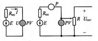
Indirect method for determining current strength in an electrical circuit
This measurement method is based on the rule: knowing the dependence of three parameters, you can always determine one of them given the known data of the other two values. For an electrical circuit, Ohm's law is valid, according to which the current strength (I) has a direct dependence on the voltage (U) or potential difference. The formula for the law for a section of the chain is as follows:
I = U/R, where R is the resistance (in Ohms) along a section of the electrical circuit. From the equation it can be seen that current has an inverse relationship with resistance.
The indirect method allows you to measure current strength both empirically and by mathematical calculations. In the first case, the initial values of voltage and resistance are determined by a voltmeter and ohmmeter. In the second option, this data is taken from the calculated parameters of the electrical circuit. It must be remembered that when mathematically calculating the parameters of an electrical circuit, absolute values corresponding to ideal data will be obtained. In practice, they can differ significantly due to the characteristics of materials, external factors, etc.
Also, with the indirect method, you can determine the required parameters knowing the power consumption of the device (P), which is the product of voltage and current (P = U x I).
Three resistances in one shunt resistor
Despite their appearance, modern shunt resistors are not as simple as they seem. Specifically, the resistance of a shunt resistor is actually made up of three parts (Figure 2). First, there is the resistance of the shunt resistor itself. Then, there are the resistances of the terminals of this resistor and the traces on the circuit board connected to the shunt resistor. Typically the lead and trace resistances are negligible, but the shunt resistors themselves usually have very low resistance values. When measuring large currents, even small lead resistances introduce an error into the measurement results, since they are not taken into account by the manufacturer in the shunt resistor specifications.
Rice. 2. A two-terminal current shunt resistor actually consists of three resistances connected in series: the resistance of the shunt resistor itself (Rshunt), the resistance of the two leads of the resistor (Rlead), and the resistance of the lead paths on the board connected to the resistor (not shown). Lead resistance may cause measurement error for large currents.
One way to avoid measurement errors introduced by external lead resistances is to create a Kelvin connection by making separate current sense paths to a two-terminal shunt resistor (Figure 3).
Rice. 3. Kelvin connection with two-terminal current sensing resistor reduces the measurement error caused by the resistance of the resistor leads and PCB traces. An example image of two-terminal current shunt resistors is shown on the right.
In this configuration, the current flowing through the current shunt resistor is routed through wide lead traces on the PCB. Much narrower traces, which are not in the main current path, but located directly next to the resistive element of the shunt resistor, remove the voltage dropped across it and transfer it to the AFE input. The separation of current-carrying and current-sensing contacts characterizes the Kelvin connection.
The resulting schematic representation of a Kelvin connection using a two-terminal shunt resistor is shown in Fig. 4.
Rice. 4. Using a Kelvin connection with a two-terminal shunt resistor removes the voltage measurement lines from the main current circuit, resulting in a more accurate voltage measurement across the shunt resistor
A very small current flows through the two current sense resistors (Rsense) shown in Fig. 4 because they are connected to the high-impedance inputs of the amplifier or ADC, which makes their resistance much less critical than the resistance values of the terminals through which the high current of the shunt resistor flows. Therefore, the voltage drop across Rsense resistors is quite small and is not a significant source of error when measuring current.