The purpose of the welding rectifier is to modulate the current coming from the household network. At the output, it must be converted to direct current with certain parameters. The main indicator of equipment for welding work is the generated current, expressed in Amperes. This indicator depends on the technical characteristics of the rectifier, which is inherently a more advanced transformer. It is not only capable of modulating electric current, but also rectifying it.
This is the main difference between AC and DC welding machines. Additionally (in addition to rectifiers), the devices are equipped with capacitors and semiconductor filters designed to level out DC pulses and make it uniform. In accordance with the requirements of welding technology, the use of rectifiers is more appropriate than transformers. In this case, the arc is more stable, and the metal spatters much less.
Design and principle of operation
Rice.
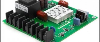
1. Design of a welding rectifier The very concept of a welding rectifier was introduced in clause 150 of GOST 2601-84. The design of such a device includes several blocks for implementing various functions, namely:
- Transformer – used to convert alternating voltage and current. In a welding rectifier, these are step-down transformers designed to reduce the 230 V network voltage and proportionally increase the secondary circuit current.
- Rectifier - made of semiconductor elements, usually assembled into a bridge circuit. Switching diodes or thyristors are often used as elements.
- Protection unit – protects equipment from overloads, emergency situations or welder errors.
- Control panel – is a module for adjusting, connecting and monitoring operating parameters.
Rice. 2. Welding rectifier control panel
- Cooling radiator - during the welding process, enormous heating occurs of the current-carrying parts of the secondary winding of the transformer and semiconductor elements. To prevent overheating of the welding device, cooling radiators are installed, in some particularly powerful models with forced ventilation.
- Starting device - designed to start the welding installation, in some situations it can shut down in the event of short circuits and other problems.
- Welding cables with electrode holders are used to supply voltage to the welding site, secure the electrodes, and provide good electrical contact.
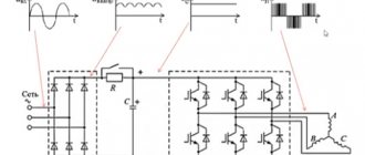
The operating principle of a welding rectifier is based on the conversion of electrical energy, both in magnitude and type of current. To do this, the mains voltage, after turning on the starting device, is supplied to the primary winding of the step-down transformer. An electric current will begin to flow in the primary winding, which generates an EMF of mutual induction with the secondary winding. Where its own emf is induced, causing the potential difference at the secondary terminals.
Rice. 3. Operating principle of the welding rectifier
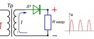
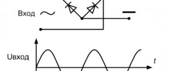
The voltage from the secondary winding will be supplied to the rectifier. A positive half-wave voltage will be passed through one pair of bridge diodes to the load. And the negative half-wave will be passed by another pair of diodes to the electrode and the workpiece. In this condition, the voltage at terminals ‟+‟ and ‟–‟ is present in the idle state without load.
As soon as a load in the form of an electrode and a workpiece for welding is applied to the ‟+‟ and ‟–‟ terminals, a working current begins to flow in the rectifier circuit. Capacitor C is used to smooth the voltage at the output of the rectifier. In addition to capacitance, the circuit may use an inductor to prevent sudden increases in current. Some models of welding rectifier may use a regulator for the operating current.
Specifications
When choosing a specific welding rectifier model, you must be guided by the type and thickness of the workpieces that you will need to weld. And also take into account the characteristics of the network to which you are connecting.
The main technical characteristics of welding rectifiers include:
- Supply voltage and its type;
- Welding rectifier power;
- Rated current and range of its regulation (if such a function is available);
- Rated output voltage;
- Cross-section of supply wires and welding cables;
- Relative load duration;
- The degree of protection against dust and moisture (indicated by the IP index) for some types of welding rectifiers is regulated in accordance with clause 4.2 of GOST 13821-77;
- Cooling type;
- Dimensions and weight.
The above characteristics are selected individually, depending on the expected conditions. In certain situations, you may want to omit some options when making selections.
Varieties
Welding rectifiers are divided into several categories, depending on the criterion. Thus, all units are conventionally divided into single-phase and three-phase devices.
Rice. 4. Single-phase and three-phase welding rectifier
Based on the number of posts that one rectifier can serve, single-post and multi-post models are distinguished. The first option is suitable for professional activities, the second is intended for use on an industrial scale.
Rice. 5. Example of a multi-station welding rectifier
Depending on the ratio of current and voltage at the output of the rectifier, there are devices with a rigid, falling (steep and flat) or increasing current-voltage characteristic.
Rice. 6. Separation of welding rectifiers according to the type of current-voltage characteristic
The most common rectifiers are those with steep and flat slope characteristics. The first type is used for manual welding with tungsten and steel stick electrodes. The second type is applicable for mechanized welding performed in an inert gas environment.
According to the type of regulation of the current value at the output of the welding rectifier, they are distinguished:
- Transformer ones are the simplest, since adjustment is made by switching the number of turns in the winding. Which changes the magnitude of voltage and current.
- Transistor - adjustment is carried out by introducing the transistor into switch mode, which slightly opens or closes the circuit according to the amount of current passed.
- Adjustable by choke - by changing the inductive reactance in the secondary winding circuit of the transformer, you can reduce the voltage supplied to the rectifier bridge.
- Thyristor - switches the operating current thanks to a separate element.
- Inverter - increase and decrease the operating value of the rectifier by converting high-frequency currents. Used in double conversion installations.
7. Conversion in an inverter welding rectifier Depending on the magnitude of the operating current, welding rectifiers are divided into:
- household - with current up to 200 A;
- semi-professional - with load capacity up to 300 A;
- professional – the amperage of which exceeds 300 A.
Video description
How to assemble a diode bridge
There are also other ways to classify welding equipment. The one that is based on the use of various types of characteristics is often used:
- Rectifiers, which are characterized by steep characteristics, are usually used for manual arc welding. They are also used for working with non-consumable electrodes in a special gas environment. Such a device is capable of creating radio interference, which is suppressed by using appropriate filters.
- Devices with rigid characteristics are used to work with electrodes that melt in carbon dioxide.
- Universal devices can be used for all types of welding work.
These devices must be distinguished by the strength of the current used. Power diodes are designed to operate in cases where it is significant. Industrial level welding machines designed for a three-phase voltage of 380 V can operate with a current of up to 400 A. For single-phase it is 125-180 A.
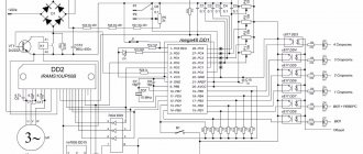
Operating principle of a welding machine circuit Source ice-people.ru
Advantages and disadvantages
Compared to other types of welding equipment, the rectifier is characterized by a number of significant advantages:
- Has greater efficiency and lower losses at idle;
- Smaller dimensions and weight, does not produce as much noise during welding as AC machines;
- The electrode heats up faster than when an alternating voltage is applied to it;
- Stable arc, resulting in an even seam;
- Metal spattering is minimized, which improves the quality of work;
- Allows you to reduce the rate of electrode consumption, which makes such devices more economical;
- It is easier to control the operating parameters of the welding rectifier;
- More durable and reliable in operation;
- Provides uniform loading of phases in a three-phase circuit.
The main disadvantage of welding rectifiers is their rather high cost. They are also sensitive to long-term short circuits, from which they need to be additionally protected, and are afraid of voltage surges in the supply network.
Adjusting the welding current
The welding current in the rectifier is adjusted using electromechanical or electrical methods. Electromechanical adjustment of welding current involves performing this operation before the rectifier unit . In this case, the rectifying valves are supplied with alternating current, which already has the parameters required for welding. Electrical adjustment is possible on rectifiers equipped with thyristors, and consists of changing the angle of their adjustment.
Purpose
Such a direct current apparatus is designed to perform welding operations in a wide variety of areas of human activity. They are widely used for work on both high-carbon and low-carbon steels, non-ferrous metals, aluminum and titanium alloys, cast iron, stainless steel and for reverse polarity welding. By type of welding, rectifiers are designed for:
- Manual arc with MMA coated electrode;
- By melting the metal under MIG shielding gases;
- Argon-arc using a non-consumable TIG electrode.
Where is the equipment used?
The advantages of DC welding over AC welding allow its use when making critical connections. It is used when welding the following metals:
- heat-resistant, high-alloy, low-carbon, corrosion-resistant steels;
- titanium;
- cast iron;
- alloys based on copper and nickel and much more.
DC welding is widely used in all areas of industry, in large enterprises, construction sites, small workshops, among home craftsmen in country houses and garages.
Maintenance and basic faults
Before starting work, the welding machine must be blown out of dust, for which you can use a regular hair dryer. After a long period of inactivity, semiconductor elements require a boost from idle mode with a smooth load to nominal. This buildup takes about 2 hours. During the welding process, it is necessary to constantly monitor the degree of heating to prevent the welding rectifier from malfunctioning.
During operation, several types of malfunctions may appear, the most common are:
- Does not turn on when voltage is applied - check the integrity of the cable and plug, the position of the circuit breaker and the condition of the protection unit, an open circuit in the device.
- Sticking of electrodes on the workpiece - the capacitor, inductor or semiconductor elements have burned out. The supply voltage may be below the nominal value.
- A sudden shutdown during welding means a breakdown of the transformer insulation, overheating is possible, and the cooling system cannot cope.
- Unstable voltage at the output - the cause may be poor contact of the terminals, the regulator knob is acting up due to loose contact or the appearance of play.
How to connect a ballast, ballast rheostat
Ballast rheostat (ballast) is a circuit device with a welding rectifier, with the help of which the welder adjusts the current. The regulation principle is based on the action of Ohm's law, known in electrical engineering. The higher the resistance that the ballast represents, the lower the current.
Ballast rheostat Ballast rheostat Brima RB-302. Photo VseInstruments.ru
Typically, a ballast is a spring, the efficiency of which depends on the optimally selected length of the spring, the diameter of the coils and wire, as well as the material from which it is made. A regulator contact is connected to the spring, moving it in the direction of winding changes its resistance, and therefore the current strength. The regulator contact is connected to the wire of the welding machine holder. The other end is connected to the power supply.
