Electronics and complex electrical circuits often require dividing the incoming voltage. For these purposes, a device called a divider is introduced into the circuit. The article will describe what a voltage divider is, what this element is needed for and where it is used. Various options for this device, formulas, as well as methods for calculating its parameters will be given.
Voltage divider formula
For this reason, a series circuit is often called a voltage divider due to its ability to proportionally divide the total voltage into fractional parts with constant coefficients. With a little algebra, we can derive a formula to determine the voltage drop across a series resistor without considering anything other than the total voltage, the resistance of the individual resistor, and the total resistance.
Voltage drop across any resistor:
\[E_n = I_n R_n\]
Current in series circuit:
\[I_{general} = \frac{E_{general}}{R_{general}}\]
Substitute Etot/Rtot instead of In into the first formula...
Voltage drop across any resistor in a series circuit:
\[E_n = \frac{E_{general}}{R_{general}} R_n\]
or
\[\large E_n = \frac{R_n}{R_{general}} E_{general}\]
In a voltage divider circuit, the ratio of the individual resistance to the total resistance is equal to the ratio of the individual voltage drop to the total supply voltage. This formula is known as the voltage divider formula, and it is a shorthand method for determining the voltage drop in a series circuit without performing Ohm's Law current calculations.
Current strength in the circuit when resistors are connected in series
Let's make sure that the current strength when connecting resistors in series is the same everywhere. I wrote here how to measure constant voltage current. As you can see, the multimeter showed a value of 0.04 A or 40 mA at the beginning of the circuit, in the middle of the circuit and even at the end of the circuit. Wherever we break our circuit, the current value is the same everywhere.
An example of using the voltage divider formula
Using this formula, we can re-analyze the voltage drop in the example circuit in fewer steps:
Figure 7 – Series circuit diagram
\[E_{R1} = 45\V\\frac{5\kOhm}{22.5\kOhm} = 10V\]
\[E_{R2} = 45\V\\frac{10\kOhm}{22.5\kOhm} = 20V\]
\[E_{R3} = 45\V\\frac{7.5\kOhm}{22.5\kOhm} = 15V\]
Capacitive reactance formula
We already know that capacitive reactance is inversely proportional to the frequency and capacitance value of the capacitor. Thus, the reactance formula is :
X C = 1 / 2πfC
XC = capacitor reactance in ohms (ohms)
f = frequency in hertz (Hz)
C = capacitance of the capacitor in farads (F)
π = numeric constant (22/7 = 3.142)
Potentiometers as Voltage Sharing Components
One device often used as a voltage divider is a potentiometer, which is a resistor with a movable element moved by a knob or lever. A moving element, usually called a slider, comes into contact with a resistive strip of material at any manually selected point:
Figure 9 – Potentiometer
The slider pin is a left-facing arrow drawn in the middle of the vertical resistor symbol. As it moves up, it contacts a resistive strip closer to terminal 1 and further away from terminal 2, decreasing the resistance from it to terminal 1 and increasing the resistance from it to terminal 2. When moving down, the opposite effect occurs. The resistance measured between terminals 1 and 2 is constant for any slider position.
Figure 10 – Operating principle of the potentiometer
Rotary and linear potentiometers
The internal workings of two types of potentiometers, rotary and linear, are shown below.
Linear potentiometers
Figure 11 – Linear potentiometer design
Some linear potentiometers are actuated by the straight-line movement of a lever or slide button. Others, like the one pictured above, are operated by a turning screw for precise adjustment. The latter type of potentiometer is sometimes called a "trimper" because it works well in applications that require a variable resistance to be "tuned" to some precise value.
It should be noted that not all linear potentiometers have the same pin assignments as shown in this figure. For some, the slider pin is located in the middle between the two extreme pins.
Rotary potentiometer
The image below shows the design of a rotary potentiometer.
Figure 12 – Rotary potentiometer
The photo below shows an actual rotary potentiometer with the slider and resistive element open for easy viewing. The shaft that moves the slider is turned almost all the way clockwise, so the slider almost touches the left end terminal of the resistive element:
Figure 13 – Rotary potentiometer with open slider and resistive element
Here's the same potentiometer with the slider shaft moved almost all the way counterclockwise, so the slider is now near the other extreme end of the stroke:
Figure 14 – Potentiometer with the slider shaft turned all the way counterclockwise
Effect of adjusting the potentiometer on the circuit
If a constant voltage is applied between the outer terminals (along the entire length of the resistive element), the position of the slider will divert a portion of the applied voltage measured between the slider terminal and either of the other two terminals. The value of the division factor depends entirely on the physical position of the slider:
Figure 15 – Potentiometer as a variable voltage divider
Current Divider Circuit Application Example: Electrical Metering Circuit
Current divider circuits also find use in measurement circuits where a portion of the current being measured is required to pass through a sensitive device. Using the current divider formula, you can select a suitable shunt resistor so that exactly the specified proportion of the total current always passes through the measuring device:
Figure 7 – Measuring circuit
The Importance of Potentiometers
As with a fixed voltage divider, the voltage division ratio of a potentiometer strictly depends on the resistance, not the magnitude of the applied voltage. In other words, if a potentiometer knob or lever is moved to the 50 percent position (the exact center position), the voltage drop between the slider and any end terminal will be exactly 1/2 of the applied voltage, no matter what happens to that voltage or what the total potentiometer resistance. In other words, the potentiometer works as an adjustable voltage divider, where the voltage division ratio is set by the position of the slider.
This application of a potentiometer is a very useful means of obtaining a variable voltage from a fixed voltage source such as a battery. If the circuit you are building requires a certain amount of voltage that is less than the voltage value of an available battery, you can connect the external terminals of the potentiometer to that battery and "select" for use in your circuit any desired voltage between the slider and one of the external terminals potentiometer:
Figure 16 – Using a potentiometer
When used this way, the name "potentiometer" makes sense: it "measures" (controls) the potential (voltage) applied to it, creating a variable voltage division factor. This use of a three-pole potentiometer as a variable voltage divider is very popular in circuit design.
Addition of schemes
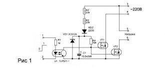
When creating ULF circuits, engineers need to underestimate the high-voltage current value to ensure normal operation of the transistor. A divider helps cope with this task. For example, such a resistor device is used to power the base terminal of a transistor. This creates a negative feedback loop for the electric current, which occurs due to the presence of resistor R3. The cascade amplifier circuit according to the OE circuit is shown in the figure below.
When designing stabilizers, a zener diode is used as part of a balanced divider. This circuit helps reduce the load on the device and significantly equalize the output current. A zener diode, like a diode, works for breakdown if the reverse current reaches a certain value.
The main difference is that when the threshold value increases, thermal and electrical breakdown does not occur in the zener diode due to a linear potential difference.
Examples of small potentiometers
Shown below are several small potentiometers that are commonly used in consumer electronic equipment and by hobbyists and students when building circuits:
Figure 17 – Examples of small potentiometers
The smaller devices on the left and right are designed to be connected to a solderless breadboard or soldered to a PCB. The devices in the middle are designed to be mounted on a flat panel with wires soldered to each of the three pins.
Below are three more potentiometers, more specialized than the set just shown:
Figure 18 – Examples of larger potentiometers
The large Helipot is a laboratory potentiometer designed for quick and easy connection to a circuit. The device in the lower left corner of the photo is the same type of potentiometer, but without the housing and rotary counting dial. Both of these potentiometers are precision devices that use multi-turn helical resistive bands and slider mechanisms for precise adjustment. The device in the lower right corner is a panel mount potentiometer designed for use in harsh industrial environments.
Definition
An electrical voltage divider is a circuit consisting of a combination of electronic components required to divide the effective incoming voltage into parts and then transfer these parts to different parts of the circuit. It is used very often in amplifiers for various purposes.
Voltage dividers can be built using various elements. They can be resistors, capacitors, and inductors. Regardless of what components the device is built from, it consists of 2 main parts:
- Upper shoulder. It includes a section with a positive value and a connection point to the next section of the circuit.
- Lower shoulder. It consists of a section with zero and is the midpoint of the chain.
Both arms have a strictly serial connection. The sum of their output voltages is equal to the total input value minus a small amount of dissipation.