Hello, dear readers of the site. Uninterrupted power supply to electricity consumers: industrial enterprises, banks, hospitals, television and radio centers, cellular operators, country houses, etc. has always been relevant. After all, a sudden power outage, especially for a long time, can lead to unpredictable consequences.
One of the ways to supply uninterrupted voltage is to separate the consumer's power supply from two independent sources of electricity, one of which is the main one
(working) and the second
as a reserve
. The working line of the substation is used as the main source, and the second (backup) line of the substation, an autonomous current generator or an uninterruptible power supply device can be used as a backup source.
In an emergency situation when voltage from the main source of electricity disappears, it is important to ensure that the backup source is quickly switched on. For these purposes, an automatic reserve input (abbreviated as AVR ) is used, which automatically switches the voltage supply between working and backup sources, ensuring a continuous supply of electricity to the consumer.
In fact, the process of switching between working and backup sources is very important and includes a whole range of functions and parameters that ensure reliable operation of the automatic transfer system. Therefore, at substations and distribution points of electrical networks, complex multi-level ATS circuits are used, including logical, measuring and power parts.
In this article, we will consider only simple electrical circuits for automatic transfer of a reserve , made on contactors, and also analyze the ATS circuit using a phase control relay . You can easily implement all these schemes in your home electrical network, and thereby ensure uninterrupted power supply to household equipment.
Simple ATS circuit for 2 inputs
The simplest ATS circuit for two single-phase inputs is assembled on just one magnetic starter. To do this you will need a contactor with two pairs of contacts:
- normally open
- normally closed
If your contactor does not have these, you can use a special attachment.
Just keep in mind that the contacts of most of them are not designed for high currents. And if you decide to connect the load of the entire house through the ATS, then you certainly shouldn’t do this using the block contacts located on the sides of standard starters.
For these purposes, it is better to choose equipment that initially has power closed and open contacts in its design. Suitable brands are VS 463-33 or ESB-63-22, MK-103 from DeKraft, KM IEK.
Here is the simplest AVR diagram:
How does the AVR work?
There are two types of system that differ in the type of input:
The ATS is a one-way type where there is one working input that is used until the problems with the main line go away. The system has a second - backup - input, which is connected in cases of emergency.
A double-sided ATS does not have a separation based on operating and backup principles, since both inputs are a priority.
The first type is characterized by the presence of a function that makes it possible to switch to the operating mode as soon as the main mode is restored. The two-way type of ATS has its own advantages, so such a function is not provided there. And in the second case, there is no fundamental difference from which source the load comes.
You can see examples of both one-way and two-way operation of the ATS system.
Description and principle of operation
The magnetic starter coil is connected to one of the inputs. In normal mode, voltage is supplied to the coil, it closes contact KM1-1, and contact KM1-2 opens.
SF1 and SF2 in the circuit are single-pole circuit breakers.
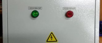
The voltage is supplied to the consumer through the contactor. Additionally, signal lamps can be connected to the circuit. They will visually show which of the inputs is currently connected. Slightly modified diagram with light bulbs:
If the voltage at the first input disappears, the contactor is removed. Its contacts KM1-1 open, and KM2-1 close. Voltage begins to flow to the consumer from input No. 2.
If you just need to check the functionality of the circuit in normal mode, then turn off the SF1 machine and watch how the assembly reacts. Is everything working properly?
The most important thing here is to initially check what current these normally closed and open contacts are designed for.
Please note that this simple circuit can be assembled in two ways:
- without zero break
- with a break in the neutral wire
Purpose of AVR
Long interruptions in power supply lead not only to discomfort and inconvenience. They can cause serious property damage and pose a threat to the life, health and safety of people.
Consumers of the 1st category can be simultaneously connected to two power sources. If one of them is turned off, electricity will still flow to the consumer. However, this scheme has significant drawbacks. When short circuit currents appear, their parameters will be significantly higher compared to separate power supply.
Electricity losses in the supply transformer will significantly exceed the norm. A more complex relay protection system will be required. Sometimes the simultaneous operation of two power supplies becomes impossible due to the equipment and relay protection that were installed previously.
Reserve input circuit with zero break
Without a break, it can be used if you have two independent power lines or cable inputs, from which you actually connect the entire house. But when the backup line is some kind of autonomous energy source - a UPS or a generator, then you will have to break both the phase and the neutral.
Since the main network in 90% of cases is made with a solidly grounded neutral, and from a generator or UPS it comes with an isolated one. Here it is impossible to combine the zero working conductor from the network with the zero from the generator.
Naturally, all contactors are connected after the kWh meter. QF are modular circuit breakers in a home panel.
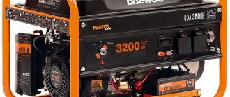
If you have a second power source that does not supply voltage automatically, for example, a gasoline generator without starting equipment. Which must first be manually started, warmed up and only then switched, then the circuit can be slightly changed by adding one single button.
Due to this, automatic switching will not occur. You choose the right moment for this by pressing it when needed. This button SB1 is mounted parallel to the contactor coil.
When the voltage at the main input does not disappear for a long time, but periodically disappears and appears (the reasons may be different), in this case it is not advisable to constantly switch the contactors back and forth. Here it is advisable to use a special attachment to a PVI-12 type contactor with a time delay.
On what basis does automatic reserve entry take place?
Regardless of the type of connection on a one-way or two-way basis, the system has a function for monitoring network parameters. For these purposes, a voltage control relay is used, as well as microprocessor control units, which does not affect the operation of the system as a whole. For example, you can consider the principle of operation of an ATS to ensure uninterrupted power supply for a single-phase consumer.
A simple circuit of a single-phase ATS
Designations:
- N – Zero.
- A – Working line.
- B – Backup power supply.
- L – Lamp acting as a voltage indicator.
- K1 – Relay coil.
- K1.1 – Contact group.
In normal mode, voltage is supplied to the indicator lamp with relay coil K1. Thus, the position of the normally closed (and normally open) contact changes. The load comes from the main source, line A. Voltage B disappears at input A, the lamp goes out, and the relay coil stops saturating, which, accordingly, leads to the contacts returning to their initial position. Thus, the load is switched on at input B.
When the voltage is restored at the main input, the relay is re-switched to source A, which corresponds to the principle of operation of a single-sided source.
This is a simplified diagram illustrating the processes occurring in the automatic transfer system, which is usually taken as an example for explanation.
ATS circuit for 2 starters
The second scheme is a little more complicated. It already uses two magnetic starters.
Let's say you have two three-phase inputs and one consumer. The circuit uses magnetic starters with 4 contacts:
- 3 normally open
- 1 normally closed KM1
The starter coil KM1 is connected through phase L3 from the first input and through the normally closed contact KM2. So when you apply power to input #1, the coil of the first starter is closed and the entire load is connected to voltage source #1.
The second contactor is turned off, since the normally closed connector KM1 will be open at this moment, and power will not be supplied to the coil of the second starter. When the voltage disappears at the first input, contactor-1 disappears and contactor-2 turns on. The consumer remains with the light.
The main advantage of these schemes is their simplicity. The downside is that such assemblies can be called automation schemes with a very big stretch.
As soon as the voltage disappears in the phase that powers the switching coil, you can easily get a counter short circuit.
You can, of course, improve the entire system by choosing a contactor coil not for 220V, but for 380V. In this case, control will be carried out in two phases.
But you still won’t protect yourself 100%. And if you take into account the moment of possible sticking of contacts, then even more so.
In addition, you will not be protected in any way from too low voltage. Starter No. 1 can turn off only if U at the input is below 110V. In all other cases, your equipment will continue to receive low-quality electricity, although it would seem that there is a second serviceable input nearby.
To increase reliability, you will have to complicate the circuit and include additional elements in it:
- voltage relay
- phase control relay, etc.
Therefore, recently, to assemble ATS circuits, special relays or controllers—the “brains” of the entire device—have increasingly begun to be used. They can be from different manufacturers and perform the function of not only turning on backup power from one source.
Suddenly you are faced with a more difficult task. For example, it is necessary for the circuit to control two inputs at once and, in addition, a generator. Moreover, the generator should start automatically.
The working algorithm here is as follows:
1.If input No. 1 is faulty, automatic switching to input No. 2 occurs. 2. If there is no voltage at both inputs, the generator starts and the entire load is switched to it.
Complete set of cabinet and panel
The configuration and operating rules of backup power input cabinets of types AVR-RN, AVRPA, AVRR are practically no different from each other. The device is a rectangular welded product with two doors.
There are two panels mounted inside on which power and control devices are installed. When operating in networks with currents up to 100 A, cabinets made on the basis of PM 12 starters with silver contacts are used.
For currents above 100 A, vacuum contactors are installed. All connections of input and output circuits are made with a tool that ensures stable contact. Clamps designed for connecting stranded copper and armored wires with lugs are installed in the cabinet.
Installed starters must be designed for 300 thousand operations, and the shutdown time of the machines during a short circuit does not exceed 0.05 seconds. All devices must have appropriate symbols, and additionally, explanatory tags must be installed under them.
Cabinets usually have two cable entries: for the supply and backup wires, which are connected to pin blocks . The power part includes:
- power input block;
- output blocks connected to the corresponding machines;
- two input contactors;
- two voltage transformers.
You may be interested in Electronic voltage converter from 12 V to 220 V
The light indicators are powered by a voltage of 36 V. The installed AVR time relays provide the transformers with an uninterrupted supply of electricity. The equipment control system includes circuit breakers, warning lamps and phase control relays. The assembled cabinet can be used in conditions that exclude precipitation and at temperatures from - 45 °C to + 45 °C.
ATS circuit for 3 inputs with a generator
How and on what basis can such a reserve input be implemented? Here you can use the AVR circuit based on AVR-02 from the FiF Euroavtomatika company.
Today, the cost of such devices is comparable to the price of a good electrical cabinet enclosure from ABB. But there you will get an empty iron box, and here are smart brains that will manage and protect your entire home electrical network.
In principle, it makes sense to spend money once and protect yourself and your equipment once and for all.
Purpose and what is an AVR
The ATS system - an electrical switchboard input and switching switchgear - quickly switches the load to a backup source if problems arise with the energy plan on the main line. Before automatically switching to emergency operation, the system detects voltage problems in the input circuit and problems with the loads.
What is hidden under the abbreviation?
There are many ways to improve the operation of the energy supply system of buildings and residential buildings. Among them, AVR is of particular importance. The name ATS - automatic transfer of reserve - explains the purpose of the system. Sometimes “input” is replaced with “turn on,” which is not entirely correct. Turning on a reserve means starting a backup generator in certain cases.
AVR classification
The principle of classifying the operation of the working system allows us to identify the most complex sections of the voltage supply circuit. ATS blocks or cabinets are usually classified according to certain parameters:
by the number of reserve sections (for example, ATS for two supplies to ensure greater reliability of power supply);
by type of network (usually single-phase ATS units are used, but there are devices for switching three-phase power, used to start a generator)
by response time;
by power of switched load;
by voltage class (for example, in circuits for switching high-voltage lines).
The classification serves as a clear example of the operation of an energy supply system with control of switching from the primary source to the backup one. ATS speeds up and protects automatic switching.
What are the requirements for AVR?
To restore power supply in emergency situations, an ATS system that meets certain requirements is used.
Ensuring uninterrupted power supply from the backup input in case of problems on the main line.
The ability to restore the operation of the power supply system in the shortest possible time.
One-time connection and disconnection of the load (for any reason).
The process of transferring from the main power source to the backup unit is controlled by the ATS system before connecting to the reserve.
The ATS system monitors the serviceability of the backup equipment control.
AVR-02 reserve input unit
This device is multifunctional and can be used to build 8 different ATS circuits. Three of them are most often used:
- input#1+input#2
- input#1+generator
- input#1+input#2+generator
Let's first consider the most complex one, which has two inputs and a generator. The second input can be either from a separate 0.4 kV overhead line or directly from a cable line from the nearest transformer substation, or assembled on a battery-powered UPS with hybrid inverters.
In this case, in the version with an uninterruptible power supply, it is necessary to provide for a situation when the batteries are discharged to the permissible maximum, and then a switch to the generator occurs. This is very convenient so as not to run the diesel generator during short-term interruptions in the power supply.
What functionality does the AVR-02 have?
- it controls power elements - contactors or starters. Motor drives can also be used.
- controls phase rotation
- controls input synchronization
- generates a generator start signal
- Can be powered by external 12V battery
- measures the voltage level and turns off the faulty line with low or high voltage, automatically transferring power to the one where everything is normal
- generates an emergency signal
On the front panel of the AVR-02 there are:
- two-line liquid crystal display
- navigation buttons
- LED indicators No. 1 and No. 2 – show the connected input
- K1, K2, K3, K4 – state of the executive relays
Operating principle of AVR 02
How does the circuit assembled on the AVR-02 base work? Here are its main elements:
- KM1.1, KM2.1, KM3.1 are the power contacts of the starters
- KV1 – three-phase network monitoring relay
- contacts No. 18,19,20 – are intended for monitoring emergency circuits in motor drives
If a malfunction occurs in the motor drive, voltage is supplied to them and the relay operation is blocked.
- S1 is something like a button with which you can send a signal and forcefully block the operation of the AVR-02
Suddenly you need to carry out some commissioning work. Here you can use the modular option from IEK KMU11.
- SB1 – Reset button
Needed for reset after receiving a signal at contacts No. 18,19,20. Press it and the relay's operation is restored.
- KM4 – intermediate relay
Thanks to its contacts, voltage can be supplied to the coils both from two inputs and from the generator. You can use the RK-1R type.
Let's consider three work algorithms and three situations for this ATS.
Input No. 1 and Input No. 2 are OK
The first input is the main one, the second one is the backup one. The device, through contacts A1, B1, C1, through the circuit breaker QF2, monitors the voltage at input-1. The same thing happens at input-2, through contacts A2, B2, C2.
Since all these contacts are normal, the AVR-02 should apply voltage to the KM coil. How does this happen?
Contacts 1 and 11 generate a control signal via relay K5. This relay K5, if the voltage level is normal on both inputs, should turn on input No. 1. That is, it is in the same position as in the original diagram. The voltage through it reaches pin 10 and goes to the KM4 coil. This is an intermediate relay. Its contacts are designated KM4.1 and KM4.2
The relay is triggered, closing its contacts and the voltage through them reaches the 22nd contact. Next, the AVR turns on relay K1. Through it and contact No. 24, the phase reaches the switching coil KM1. At the same time, other relays K2, K3, K4 remain open.
How microprocessor-based contactless systems work
ATS of this type have microprocessor control units. In operation of the device, the connection is made through semiconductor switches, which are more reliable.
Contactless automatic transfer switches have many advantages:
- There is no need for mechanical contact and there are no problems that can arise with it (burning or sticking, etc.).
- There is no need for mechanical locking.
- There is an extended range of control over all switching parameters.
The disadvantages include the difficulty of repairing an electronic type AVR. Implementing such a device scheme yourself will be problematic. You cannot do without special knowledge of electronics and programming knowledge.
With AVR water, the load on the operation of the entire system is significantly reduced, there will be fewer blockages, but it is easier to control the processes of switching electricity from the main source to the backup one and vice versa. Connection diagrams can always be found on the Internet or in the instructions.
Algorithm No. 2 - input No. 1 is faulty
The voltage at input No. 1 has disappeared. AVR-02 sees that there is no voltage on A1, B1, C1, but there is voltage on A2, B2, C2. Therefore, K5 switches to position No. 11.
Next, U from input-2 comes through 11 to 10 and then the whole circuit is repeated as discussed earlier.
Only in this case, it is not K1 that is shorted, but K2. And accordingly the coils of the KM2 contactor.
In this case, the device ensures that there is no voltage at No. 13,14,15. So that the opposite power supply does not turn on (if the contacts stick and the power supply is restored).
If there is voltage on at least one of the connectors 13-14-15, then the KM2 coil will never work. This is protection against counter voltage.
Connection diagram of a diesel generator set with an AVR to an ASU
Connecting a diesel generator set (diesel generator set) is a set of actions that should ensure that there is no emergency switching of an electrical substation, mainly due to the ATS (automatic transfer switch). These actions are integral to the startup of the power plant and its further uninterrupted operation.
Before proceeding to connecting the diesel generator set to a network device, you need to check that:
- The installation work is completely completed and the diesel generator is firmly attached to the foundation support;
- All switching devices are mechanically interlocked;
- Cables of appropriate flexibility and cross-sections have been prepared.
If there is an operating manual for the power plant, then accordingly there is a connection diagram for the diesel generator set, with the help of which it is enough to correctly connect certain cables and terminals (Fig. 1).
In the process of connecting the generator, you should connect the power, control and measuring cables, as well as the cable for your own needs. Sometimes there are cases when it is enough to connect only power cables, which are the main wires for supplying consumers with electric current. In a single-phase substation there are only two power cables, and in a three-phase substation there are four.
To connect all four wires to a three-phase substation, follow these steps:
- Each of the four cables is pulled to the ATS and connected to a specific bus. This connection method is applicable in the case of using a four-pole ATS, which consumers put into operation much less often than a three-pole ATS.
- When using a three-pole ATS, three power cables are connected to the buses of the transfer switch with the corresponding connectors, and the neutral cable is pulled inside the ATS to combine with a common zero. This method is used if the ATS has a special bus for zero.
- If there is no bus for combining the zero, three power wires are connected, and the zero is combined on a general-purpose bus located outside the transfer switch, in the main switchboard of the equipment (Fig. 2).
The use of control and measuring cables is carried out when the diesel generator set can start and operate automatically as soon as voltage is applied to it. When manually controlling the power plant, there is no need to use these cables. There are two ways to connect them for diesel generator sets with automatic transfer switch, which depend on the location of the network control unit:
- When a conventional ATS is installed, where there is no network control unit, the network is monitored through a special diesel generator test panel, which processes the mains voltage and is capable of making a decision about starting or stopping the generating set, and also controls the switching of contactors in the ATS. This connection option is used mainly for stationary substations. Here it is important to provide some nuances for connecting the control cables that extend from the control panel. Using these wires, the control panel receives information about the quality of the network power supply. You also need to connect the signal cable from the control panel to the transfer switch. Due to this wire, the control panel gives a command to switch the ATS contactors. Scheme of AVR with stationary type diesel generator set (Fig. 3).
- When an ATS with a simple control panel with an internal location of the network control unit is installed, control and measuring cables are not needed here. In this case, it is enough to just connect two control cables from the ATS to the generator set. After this, the network control unit will give a signal to start or stop the generator. This method is used mainly in all portable diesel generator sets. Diagram of an automatic transfer switch with a mobile type diesel generator set (Fig. 4).
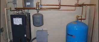
In order for the diesel generator set to work smoothly and correctly, it is necessary to use its own power supply, which contains a battery for constant recharging and heating of the coolant. The connection of the auxiliary wire is carried out from the consumer’s independent automatic main switchboard device to a separate generator block located under the control panel. Sometimes there are individual solutions where complementary devices may have their own needs:
- for heating the oil, as well as for heating the air inside a special casing that protects from different weather conditions, which covers the generator;
- separate panel for own needs.
According to clause 1.2.18 of the PUE, there is a special category of electrical receivers (EP) that operate uninterruptedly, are considered trouble-free and can prevent any threats to electricity consumers. This category includes a 3-input ATS, which is powered by three sources independent of each other. But the third source is most often used only if the voltage disappears on one of the two main sources. Although some consumers, to be on the safe side, keep it turned on at all times. This energy supply option is mainly used by oil refineries.
If there is no third independent source, then batteries, as well as diesel power plants or automatic power supply systems, are used. If the frequency in the power system decreases, then in order to ensure optimal flow of electrical supply, the independent power supply should not be disconnected by the automatic frequency load device. Electrical receivers belonging to a special group must be equipped with self-starting and a technological reserve connected to the automatic transfer switch.
The ATS diagram for three inputs, which is available in the operating instructions for the diesel generator set, clearly shows the connection points of these power supplies (Fig. 5).
While in normal operating condition, the first and second independent sources power the first section of the panel, and the third source powers the second section. If the voltage disappears at the first power source, then the armature of the starter 1KM1 returns, then the time relay 1KT1 and then 1KL2 are started. As soon as contact 1КL2 closes, the switching circuit of starter 1КМ2 immediately closes.
If the voltage disappears at the third power source, then the armature of the 2KM1 starter returns, then the 2KT1 relay is started, followed by 2KL2. As soon as the 2KL2 contact closes, the 2KM2 starter switching circuit immediately follows. After this, the second section switches to the second power source.
It happens that at the same time the voltage disappears on the first and third power sources. In this case, the first and second sections are connected to the second power source after 0.5 seconds. In this case, starter 1KM2 is triggered, and then 2KM2.
If the voltage disappears on the first or second power supply, as well as in the event of failure of the ATS inputs, the armatures of starters 1KM1 and 1KM2 return. Their contact wires, connected to each other in a certain sequence, close the circuit of the KT1 time relay. After one second, relay KL1 turns on. After contact KL1 has closed, the switching circuit of the KM1 starter follows. The first section is automatically connected to the third power source.
When the voltage disappears on two power sources at once (the first and the second), the electrical receivers are automatically turned off. But the power supply of a special group of electronic devices, which is connected to a third independent source, remains on.
When the optimal voltage supply is restored, the first section immediately switches on the 1KM1 starter, and one second later the 1KM2 or KM1 switches off. In the second section, immediately after restoration, the 2KM1 starter is turned on, and after a second, 2KM2 or KM1 is turned off.
Also, a more clear example is the ATS circuit with a diesel generator set, where a voltage of 380 V is supplied from three independent power sources. In this case, the third power source is a diesel generator set (Fig. 6).
An important nuance of this scheme is that if two inputs are disconnected manually or in an emergency, in any case the diesel generator set is automatically started along with the load being simultaneously connected. When the voltage is restored at at least one of the inputs, it also automatically switches to the original operating mode.
ATS with generator autostart
How will the generator start if the power from both inputs disappears? Contact No. 12 is used to connect an external +12V power supply to the ATS.
When you lose voltage on two inputs, all contacts K1, K2, K3 are in an open state. In this case, the internal contact of relay K4 automatically closes. Due to this, a start signal for the generator is generated.
Most generators with ATS capability control the damper with their own automation. To do this, they only need a start signal. You just serve it.
If you don’t have this, then you can make such a system yourself.
After the pulse is given, the diesel generator set starts and warms up. When it warms up, the voltage on relay KV1 reaches normal. KV1 is something like a three-phase motor protection relay.
It is necessary to control the voltage of a 3-phase network (correct phase rotation and their nominal value). For example, this would be suitable - CKF-317.
After operation, relay KV1 closes its contact KV1.1 and the voltage reaches connector No. 16. U also goes to pin No. 9 (it controls the internal circuits of the AVR) and No. 22.
AVR sees this and sends a signal to close relay K3 and coil KM3. After which the power contacts of the KM3.1 generator starter are turned on. The entire load is powered from the generator.
High-voltage circuits with ATS
The operation of automatic transfer switches in high-voltage networks of the 1 kV class has a more complex scheme, although with a similar operating principle, as stated above. All triggering mechanisms do not change here. But in this scheme there are no backup transformers and each bus (Sh1 and Sh2) is connected to its main supply transformer (T1 and T2). The latter can, in certain circumstances, become backup sources with additional load. In normal mode, the CB10 switch is open and the ATS controls the TP via TN1 Ш and TN2 Ш.
When the power is blocked at Sh1, B10T1 is turned off and SV10 is turned on. Both sections or blocks start working from the same transformer. As soon as the source restores its operation, the ATS will reconnect the system to its original position.
Simplified diagram of 110/10 kV transformer substation