The properties of the magnetic field have been studied by scientists for a long time. Electromagnetic induction was first described by Michael Faraday. Namely, how a strong electromagnetic relationship appears in the windings when alternating current is created in the first coil. In the secondary coil, the voltage increases, but the power and frequency remain the same. Of course, it is difficult for an ignorant person in electricity to understand the design, operating principle, and purpose of a transformer. However, this is an integral device with installation in many areas: radio engineering, electrical power engineering.
Voltage transformers: purpose and principle of operation
A transformer is an electrical device. Converts alternating current of one voltage into electric current of another voltage. The frequency, according to the phenomenon of electromagnetic induction, remains unchanged.
A static transformer consists of:
- primary and secondary windings;
- core.
The device is used in different power circuits and electrical appliances. Transmits electricity over long distances and:
- reduces energy losses;
- reduces the cross-sectional area of power transmission line wires.
Types of device:
- increasing;
- downward;
- power;
- rotating;
- pulse;
- dividing;
- coordinating
A step-down transformer is used in everyday life. It is through it that current passes and enters home sockets with a power of 220 W.
A power unit consisting of a core and several windings converts voltage into electrical circuits using the principle of electromagnetic induction. Also the value of AC voltage without changing its frequency. Used for distribution and transmission of electrical energy. The voltage in the windings is over 300 kV. Power – from 4 kV to 200,000 kVA.
Reference! The transformer is used to lower or increase alternating voltage. The basis is a ferromagnetic core. In addition, for uninterrupted operation - windings, insulation, magnetic circuit, cooling system.
The windings are made of insulated copper wires of rectangular cross-section. Between their layers there are voids for the circulation of cooling oil. The role of which is to take heat from the windings and transfer it through the radiator tubes to the environment.
The operating principle of the device is based on:
- change in magnetic flux;
- creating electromagnetic induction when passing through the winding;
- supplying voltage to the primary winding;
- reproduction of magnetism by an electric current that changes over time.
Alternating current flowing through the primary winding begins to create a magnetic current in the magnetic circuit. Gradually leads to flux in all windings, transforming the galvanic isolation (alternating voltage), but without changing the frequency.
Worth knowing! The operation of the device is based on electromagnetic induction. Due to alternating current, an alternating magnetic field is formed around the conductor and is modified into an electromotive force. The output voltage completely depends on the transformer used (step-down, step-up). The EMF coefficient in the windings is directly proportional to the number of turns.
Repair and maintenance
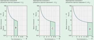
The reliability of power transformers directly depends on the quality and timeliness of their maintenance. Devices installed in premises where plant personnel work are subject to daily inspection with monitoring of oil level indicators, the condition of the absorber and regeneration devices. In addition, the integrity of the body and main elements is checked. Transformers in rooms without personnel are inspected once a month, and transformer points - twice a year.
An unscheduled inspection of a power transformer and its protection systems is carried out in case of a sharp change in ambient temperature, as well as in emergency conditions. Voltage regulation devices are also subject to periodic maintenance. The reason is the oxidation of contact groups, which leads to an increase in their contact resistance. Before seasonal load changes (usually twice a year), the device is disconnected from consumers and power, after which the voltage regulator is moved sequentially to all possible positions. The procedure helps to destroy the oxide film.
Laboratory oil analysis is performed every year during major repairs. If the oil does not meet the requirements during visual inspection (color) or according to inspection data, it is replaced or topped up.
Why do you need a voltage transformer?
A voltage transformer is a universal device. Transmits and distributes energy.
Used in:
What kind of lighting do you prefer?
Built-in Chandelier
- electrical installations;
- power supplies;
- power transmission units;
- signal processing devices;
- power supplies of devices.
A high voltage power transformer is used for:
- supplying energy to the electrical grid at power plants;
- increasing the voltage of the generator, power lines;
- reducing voltage to consumer level.
A three-phase device with a special cooling system is used in electrical networks. The core in the composition is common to all 3 phases.
The scope of application of the network transformer is power supplies, components of electrical appliances with different voltages. Pulse units are indispensable for radio engineering and electronic devices. First, the alternating voltage in the power supplies is rectified. Next, due to the inverter, high-frequency pulses are converted, stabilizing the constant voltage.
Transformers are included in many power circuits to ensure minimal levels of high-frequency interference. For example, separation devices prevent the risk of electric shock to humans. After all, connecting household appliances to the network through a transformer becomes safe.
The second circuit of the device will be isolated from contacts with the ground, unless, of course, we are talking about grounding electrical equipment. Power measuring instruments are used in alternating current generator circuits. The number of phases of the generator from the transformer must match to achieve a stable output voltage.
Matching transformers are indispensable for electronic devices with high input impedance and high-frequency lines, but with different load impedances.
What is a magnetic core in a transformer? Why is there a gap needed and more?
Mains and pulse transformers have a core or magnetic circuit made of different materials; this article will talk about this detail.
A magnetic core is a part of a transformer designed to pass a magnetic flux. This flux in a network transformer appears when the primary network winding is connected to a 220V network, which has a sinusoidal voltage waveform. An electromagnetic field is formed near this coil, the magnetic component of which is transmitted by the magnetic core and it becomes a magnet whose poles change 50 times north and 50 times south in one second. If you insert another step-down coil onto the magnetic circuit, then when a load is connected to it, an emf is induced in it.
If you measure the resistance of the TS-180 network winding, the readings will be about 6.4 Ohms, and if you take a 6.4 Ohm resistor and plug it into a 220V network, it will break or blow out the plugs. The fact is that the resistance of the resistor is active, this will be shown by the ohmmeter, and the resistance of the network winding at an alternating voltage of 220V is reactive, and it is precisely this that provides the resistance of 220V. The core in the coil increases the reactance and inductance of the winding.
The magnetic core is made of special transformer steel-iron with silicon (soft magnetic material), with high resistivity and minimal residual magnetization, a narrow hysteresis loop, and high magnetic permeability. The magnetic core is affected by Foucault currents, to reduce them the core is overlapped and laminated, and the plates are insulated from each other with varnish or a layer of oxide. The high resistivity of the core is also due to Foucault currents.
You cannot use another steel in the core, it will start to heat up and the transformer will not work well. The core may go into saturation, this is when the magnetic circuit becomes a magnet as much as possible. In this mode, the transformer will begin to emit impulse noise, which can affect the operation of radio components.
To operate in switching power supplies, a ferrite core is used, which can operate at frequencies of tens of kHz with pulses. This is also a ferromagnet, but is made of iron oxide and other additives and materials. It is not overlapped, since the Foucault currents in the core are extinguished due to due to the high resistivity of the material. The gap is made so that the core does not become saturated from magnetization, which can be caused by the constant component of the signal (non-magnetic gap).
Network and pulse transformers can be wound on a toroidal core to reduce stray fields. They are more efficient compared to conventional cores and have smaller dimensions, but winding on rings is labor-intensive, and on a ferrite ring it is also more difficult to create a gap, although it is commercially available rings with clearance.
The magnetic antenna has a ferrite core. Marking 400NN. 400 is the magnetic permeability, the higher it is, the lower the operating frequency of the ferrite. In microwaves, the core in the circuits is brass or aluminum.
How does a voltage transformer work?
The devices convert the source energy into the required voltage coefficient. They operate exclusively at alternating voltage with a constant frequency. The work is based on electromagnetic induction as a phenomenon triggered by a change in magnetic flux over time, generating an EMF in the windings.
The operation of a transformer begins in the primary winding, where the core creates magnetic flux. Next, alternating current is activated, magnetizes the core, increases the inductance of the primary winding, and prevents the increase in current at the terminals of the voltage winding. If the primary winding gives off magnetic flux, then the secondary winding receives it, changes at a certain speed, penetrating all branches and creating an EMF.
The voltage on the branches depends entirely on the rate of change of the magnetic flux in the core. Although it turns out the same on the branches of the primary and secondary windings due to the passage of the same magnetic flux through them.
It, in turn, creates an electric field around itself in the core, a kind of vortex with an effect on the electrons, starting to push them in a certain direction.
Reference! To put it simply, the principle of operation of a voltage transformer is based on excitation of voltage in the second winding due to the alternating current generated in the magnetic circuit.
Main parts of the transformer design
The main parts of the transformer design are:
- magnetic circuit
- windings
- frame for windings
- insulation
- cooling system
- other elements (for installation, access to winding terminals, transformer protection, etc.)
In practical transformer design, the manufacturer chooses between three different basic concepts:
- Rod
- Armored
- Toroidal
Neither of these concepts affects the performance or operational reliability of the transformer, but there are significant differences in their manufacturing process. Each manufacturer chooses the concept that it considers most convenient from a manufacturing point of view, and strives to apply this concept throughout the entire production volume.
While bar-type windings enclose a core, armor-type core encloses the windings. If you look at the active component (i.e. the core with windings) of the rod type, the windings are clearly visible, but they hide the rods of the core magnetic system behind them. Only the upper and lower yoke of the core are visible. In an armor-type design, the core hides the main part of the windings.
Another difference is that the axis of the rod-type windings, as a rule, has a vertical position, while in an armored structure it can be horizontal or vertical.
Voltage and current instrument transformers
Devices operating under high voltage require periodic measurements.
For these purposes, measuring devices that:
- reduce the voltage to the desired level;
- provide galvanic isolation of measuring equipment from circuits with increased danger.
Classifications
Transformers are classified according to a number of parameters, such as:
- Purpose. Used: for changing voltage, measuring current, protecting electrical circuits, as laboratory and intermediate devices.
- Installation method. Depending on the location and mobility, the transformer can be: stationary, portable, internal, external, support, busbar.
- Number of steps. The devices are divided into single-stage and cascade.
- Rated voltage. There are low and high voltage.
- Winding insulation. The most commonly used are oil-paper, dry, and compound.
In addition, converter devices come in different types, each of which has its own classification system.
Power
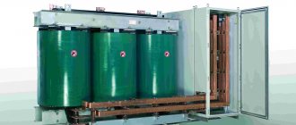
The most widely used the power transformer . Devices with direct conversion of alternating voltage, designed for high power, are in demand in various areas of the electric power industry. They are used on power lines with voltages of 35–1150 kV, in city power networks operating with voltages of 6 and 10 kV, and in providing end consumers with voltages of 220/380V. The devices provide power to all kinds of electrical installations and devices in the range from fractions to hundreds of thousands of volts.
Power transformer
Measuring
Current transformers (CTs) reduce the current to the required levels. The scheme of their operation is distinguished by the sequential connection of the primary winding and load. At the same time, the secondary winding, which is in a state close to a short circuit, is used to connect measuring instruments, actuators and indicator devices. With the help of TA, galvanic isolation is carried out, which makes it possible to avoid using shunts during measurements.
High voltage CT(left) and low voltage CT(right)
With the help of voltage transformers (VT) , the same as TA only in voltage. In addition to converting input parameters, electrical equipment and its individual elements are protected from high voltage.
High voltage transformer (left) and low voltage transformer (right)
Pulse
If it is necessary to convert pulsed signals, pulse transformers (IT) are used. By changing the amplitude and polarity of the pulses, the devices maintain their duration and practically do not affect the shape.
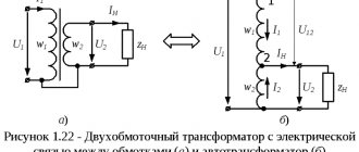
Autotransformer
In autotransformers, the windings form one circuit and interact through electromagnetic and electrical communication. Unlike other types of converters, devices can contain only 3 outputs, allowing you to operate with different voltages. The devices are distinguished by their high efficiency, which is especially noticeable with a slight difference in input and output voltage.
Single-phase (left) and three-phase (right)
Without galvanic isolation, representatives of this type increase the risk of high-voltage shock to the load. A prerequisite for the operation of devices is reliable grounding and a low transformation ratio. The disadvantage is compensated by lower consumption of materials during manufacturing, compactness and weight, and cost.
Dividing
For isolation transformers, interaction between the windings is eliminated. The devices increase the safety of electrical equipment in the event of damaged insulation.
Isolation transformer
Coordinator
Matching transformers are used to equalize resistance between stages of electronic circuits. While maintaining the signal shape, they play the role of galvanic isolation.
Peak transformer
Using a peak transformer, sinusoidal voltage is converted into pulse voltage. In this case, the pulses change polarity with each half-cycle.
Twin throttle
A feature of a dual inductor is the identity of the windings. The mutual induction of the coils makes it more efficient than standard chokes. The devices are used as input filters in power supplies, audio and digital equipment.
Twin throttle
Welding
In addition to the above, there is the concept of welding transformers. Specialized devices for welding work lower the voltage of the household network while simultaneously increasing the current, measured in thousands of amperes. The latter is adjusted by dividing the windings into sectors, which affects the inductive reactance.
Welding transformer
Rated power, voltage and current
Rated - the power with which the transformer operates in a certain accuracy class and in accordance with GOST. Expressed in volts, amperes. Minor power deviations are allowed, but not higher than the normalized values.
Important! To avoid increasing the secondary load error, the total consumption of the windings of measuring instruments and relays should not be more than the rated power of the transformer. You can find out the rated power in the passport for the unit or on the dashboard.
The rated voltage threshold of the transformer is 10 kV.
The difference depending on the power of electrical appliances is for:
- power supply for electrical receivers – 3-6.3 kV;
- large-sized electric motors – up to 1000V.
The power of a three-phase transformer is subtracted by the formula: – S=square root of the number 3 UIU—nominal phase-to-phase voltage, V; / - current in phase, A. The coefficients of operating currents in the windings in the operating state of the transformer should not be higher than the rated ones. Although short-term overloads in oil and dry units up to certain limits (2.5 -3%) are acceptable.
Converter power calculation
Each transformer has technical characteristics specified in the passport. It may be necessary to carry out independent winding and power calculations if the data is lost. The power value is important to determine whether a particular inverter can be used.
Before determining the power of the transformer based on the cross-section of the core, the type of magnetic circuit is studied. If the core has a W shape, perform the following calculations:
- measure the thickness of the set of plates;
- measure the central part;
- the results obtained are multiplied.
Faraday's law
According to the law of electromagnetic induction, an EMF voltage is created in the secondary winding. Calculated using the formula – U2 = −N2*dΦ/dt.
Reference! Faraday is the fundamental law of electrodynamics. It states that the generated electromotive force is equal to the rate of change of magnetic flux, but taken with a minus sign. It was Michael Faraday who made the discovery when, during experiments, he announced that electromotive force begins to appear in a conductor only when the magnetic field changes. The magnitude of this force is directly proportional to the rate of change of the magnetic field.
All the facts are contained in one equation. However, the minus sign in the law is Lenz’s rule, indicating the occurrence of an inductive electric current when the magnetic field in the conductor changes. The action of the current is directed towards the magnetic field, which begins to counteract the change in magnetic flux.
Lenz's rule does not obey the laws of electrodynamics, because induction current appears both in windings and in solid metal blocks.
Operating modes
The characteristics of transformers are determined by operating conditions, where the load resistance plays a key role. The following modes are used as a basis:
- Idle move. The outputs of the secondary circuit are in an open state, the load resistance is equal to infinity. Measuring the magnetizing current flowing in the primary winding makes it possible to calculate the efficiency of the transformer. Using this mode, the transformation ratio is calculated, as well as losses in the core;
- Under load (working). The secondary circuit is loaded with a certain resistance. The parameters of the current flowing through it are directly related to the ratio of the turns of the coils.
- Short circuit. The ends of the secondary winding are short-circuited, the load resistance is zero. The mode informs about losses that are caused by heating of the windings, which in professional language is referred to as “copper losses”.
Short circuit mode
Information about the behavior of the transformer in various modes is obtained experimentally using equivalent circuits.
Ideal Transformer Equations
In such a transformer, power lines pass through all branches of the primary and secondary windings. This means that there are no vortex flows and energy losses. The magnetic field changes, but generates an identical EMF in all turns, and therefore becomes directly proportional to their total number.
When energy comes from the primary circuit, it is transformed into a magnetic field and then enters the secondary circuit.
The formula for the ideal transformer equation is P1 = I1 • U1 = P2 = I2 • U2:
- R1 – coefficient of incoming power from the first circuit to the transformer;
- R2 is the coefficient of converted power entering the secondary circuit.
If you increase the voltage at the ends of the secondary winding, the current level of the primary circuit will decrease. According to the equation - U2/U1 = N2/N1 = I1/I2, converting the resistance of one circuit to the resistance of another is possible only by multiplying the value by the square of the ratio.
How to reduce losses
The magnitude of magnetization reversal losses depends on several factors:
- properties of the substance from which the core is made. Materials that are difficult to magnetize are also difficult to remagnetize. And the more energy is consumed, which is expressed in heating;
- magnetization reversal frequencies;
- the highest value of magnetic induction.
Losses are reduced through the use of special transformer steel. It requires less energy for magnetization reversal compared to other substances.
Eddy currents reach their greatest values in massive conductors due to their low resistance. To reduce them, it is necessary to increase the electrical resistance. This is achieved by assembling a core from separate sheets. The thickness of the steel plates is selected to be no more than 0.5 mm.
To prevent the sheets from melting together when heated, the plates are isolated from each other to reduce eddy current losses. Varnish and scale are used as a separator. There are chemical methods for insulating steel sheets. The interlayers provide strong resistance to eddy currents and stop their effect, which significantly reduces energy losses.
Three-phase power transformer design
The main parts of the transformer are the magnetic core and winding. The magnetic core is assembled from sheets of electrical steel 0.3-0.5 mm thick. Sheet insulation consists of coating a steel sheet with a varnish film on both sides. The magnetic core is divided into rods and a yoke. The rod is the vertical part of the magnetic circuit onto which the winding is mounted. The yoke is the horizontal part that closes the magnetic flux.
Three-phase transformers are most often made with three rods (rod type), on which three windings are located. There are two types of connection between rods and yoke - butt and laminated. Butt joint - the yoke and rods are secured with connecting parts, making it convenient to remove the windings. With a laminated connection, the yoke and rods are assembled with overlapping sheets of steel, in this case the magnetic resistance of the magnetic circuit is reduced by reducing the air gap. Also, the mechanical strength of a laminated joint is higher than that of a butt joint.
The transformer windings are made of round or square copper conductor. The insulation is cable paper or cotton yarn.
The magnetic core with the tank is grounded for safety in case of a winding break.
In oil transformers, the magnetic core with winding is lowered into a tank filled with transformer oil. The oil removes heat from the windings. The characteristics of oil are higher than those of air, therefore, the dimensions of an oil transformer and a dry transformer of the same power are more advantageous than an oil transformer.
As climate conditions change, the oil level may change. This happens not in the transformer tank, but in a special expander, which is a vessel on the tank lid that communicates with it.
Under abnormal conditions, such as short circuits, the oil pressure may change due to the release of gases in the oil. To relieve this pressure, transformers use an exhaust pipe. There is a glass plate on the top of the pipe. As the pressure increases, the plate shatters and pressure escapes from the transformer.
Powerful transformers are equipped with a gas relay. When the pressure increases due to the release of gases (for example, during short circuits inside the transformer), the relay is activated and a signal is sent to turn off the switch. After which the transformer is disconnected from the network.
The windings are connected to the network through the transformer inputs. They come in various designs: with main insulation of porcelain cover, capacitor bushings, with paper-oil, polymer, SF6, oil barrier insulation.
In transformers, it is possible to change the number of winding turns (winding connection groups). For these purposes, PBB (switch the number of turns without excitation) and RPN (regulating the number of turns under load) are used.