Purpose and types
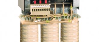
Three-phase transformer
The classic station three-phase power transformer is used to convert high-voltage energy into a form convenient for the consumer. A high voltage (6.3-10 kilovolts) is supplied to its primary windings, and the output is 220 Volts, which are more convenient for everyday use. This value is measured between the phases and the neutral conductor of the transformer, called the neutral. It is usually designated as phase voltage, in contrast to linear 380 Volts, counted between each phase.
Three-phase step-down transformers of this class provide current transmission from the local substation through an underground cable or power line directly to the end consumer. For these purposes, a special 4-core cable in an armored core or an overhead wire of the SIP brand is used. Through them, electrical energy is delivered directly to its destination - to the input and distribution devices of the serviced territories and facilities.
According to their functional purpose, 3-phase transformers are divided into the following classes:
- linear (station) devices;
- special converting units.
Particularly noteworthy are three-phase isolation transformers used for decoupling electrical circuits and power circuits.
Test transformer
Special devices are divided into the following types:
- Test transformers. These include three-phase autotransformer systems.
- Devices used to power special equipment: welding units, in particular.
- Balancing transformer units.
The first two types are used for research purposes. Three-phase balancing transformers are used to eliminate phase imbalance that occurs in electrical networks due to uneven load distribution.
In electrical engineering there are also variants of two-phase transformers, often used in electronic circuits and automation devices. They are designed so that the two output voltages are shifted relative to each other by 90 electrical degrees. Most often, such electrical solutions are used in welding equipment.
How to choose a step-down transformer?
If you have little knowledge of electrical engineering, choosing a step-down transformer will be difficult, and you will have to entrust this to specialists. But when deciding to choose the right device yourself, pay attention to the following indicators:
- The indicated power of household or industrial appliances must be less than that indicated on the transformer;
- The input voltage into which the device will be installed must be suitable;
- The output voltage must match the transformer.
Try not to choose cheap models, because a high-quality modern converter must withstand emergency situations and operate stably after they are detected. For example, short circuits, network overvoltage, and network overload often occur.
The device is selected specifically for your requirements; the main parameter is the input voltage. During visual inspection, the input voltage is written on the product. For example, a step-down transformer with 220 V or 380 V. The output voltage marking should also be indicated on the case, for example 12 or 36 Volts.
Be sure to pay attention to the power of the device, because when selecting a voltage stabilizer, you will have to add the power of all future devices used and add another 20% of the obtained figure.
Transformer device
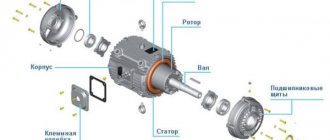
Design of a three-phase power transformer
According to their design, three-phase transformers represent a prefabricated structure consisting of the following components:
- base, made in the form of a durable plastic frame;
- magnetic circuits placed in frame sections;
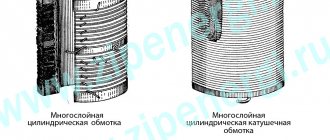
- a set of primary and secondary coils with wire windings;
- distribution (soldering) panel with contact blocks;
- cooling system necessary to remove heat from the work area.
Each of the known versions of such devices in one form or another contains all the designated nodes.
However, they differ in the way the windings are connected, as well as the type of magnetic circuit used in them. The design features of individual models are reflected in their performance characteristics, in particular the magnitude of losses in the magnetic circuit and efficiency. The exception is the panel for wiring taps of transformer windings, thanks to which it is possible to combine groups of connections to obtain the desired configuration.
Winding connection methods
Connection diagrams for windings of three-phase transformers
The main difference between various transformer diagrams is the configurations used when they are turned on (methods of connecting the windings). When organizing centralized energy supply, two classical schemes are traditionally used, called “triangle” and “star”. The first option involves sequential connection of the primary and secondary phase windings: the end of one coil is connected to the beginning of the next).
When using a star circuit, the beginnings of all the phase conductors of the primary and secondary windings are combined at one point, called the neutral, and their ends are connected to a 3-wire load line. In this case, a cable containing four cores will be required to transmit electricity. When connecting secondary transformer windings connected in a “triangle” to the line, only three cores are used. Another option for their inclusion is possible, which is called “interconnected star”. However, due to the rarity of its use, it is not considered.
Configuration options
Winding options
When organizing power supply systems, several combinations of connecting the primary and secondary windings of a three-phase transformer are possible. The set of switching actions performed in this case:
- The primary winding is made as a “star”, and the secondary winding is made as a “triangle”.
- The second approach uses the reverse order of inclusion.
- In the third case, the already discussed combination of the “star”-“star” type or the option with two triangles (another name is delta-delta) is used.
To take into account all methods of connecting primary and secondary windings and subsequent calculation of transformer parameters in electrical engineering, special identification tables are used. They provide possible combinations and combinations used if you want to connect a transformer to a line and get the most out of it. The efficiency of the entire energy supply system depends on the correct choice of this combination in each specific case.
Detailed working principle of 3 phase transformer
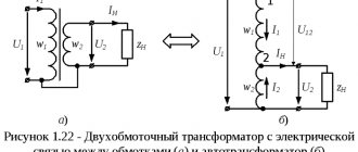
Three-phase current can be transformed by three completely separate single-phase transformers. In this case, the windings of all three phases are not magnetically connected to each other: each phase has its own magnetic circuit. But the same three-phase current can be transformed by one three-phase transformer, in which the windings of all three phases are magnetically connected to each other, since they have a common magnetic circuit.
To understand the principle of operation and structure of a three-phase transformer, let’s imagine three single-phase transformers placed one next to the other so that their three rods form one common central rod (Fig. 1). On each of the other three rods, primary and secondary windings are superimposed (the secondary windings are not shown in Fig. 1).
Let us assume that the primary coils of all transformer bars are exactly the same and wound in the same direction (in Fig. 1 the primary coils are wound clockwise when viewed from above). We connect all the upper ends of the coils to neutral O, and connect the lower ends of the coils to the three terminals of the three-phase network.
pic 1
The currents in the transformer coils will create time-varying magnetic fluxes, which will each be closed in its own magnetic circuit. In the central composite rod, the magnetic fluxes will add up and give a total of zero, because these fluxes are created by symmetrical three-phase currents, regarding which we know that the sum of their instantaneous values is equal to zero at any moment of time.
For example, if the current I in the AX coil was greatest and passed in the direction indicated in Fig. 1 direction, then the magnetic flux would be equal to its greatest value Ф and would be directed in the central composite rod from top to bottom. In the other two coils BY and CZ, the currents I2 and I3 at the same moment in time are equal to half the highest current and have the opposite direction with respect to the current in the AX coil (this is the property of three-phase currents). For this reason, in the rods of the BY and CZ coils, the magnetic currents will be equal to half the highest flux and in the central composite rod will have the opposite direction with respect to the flux of the AX coil. The sum of the flows at the moment under consideration is zero. The same is true for any other moment.
The absence of flow in the central rod does not mean the absence of flows in the remaining rods. If we destroyed the central rod, and the upper and lower yokes were connected into common yokes (see Fig. 2), then the flux of the AX coil would find its way through the cores of the BY and CZ coils, and the magnetomotive forces of these coils would add up to the magnetomotive force of the coil OH. In this case, we would get a three-phase transformer with a common magnetic circuit of all three phases.
Figure 2.
Since the currents in the coils are shifted in phase by 1/3 of a period, the magnetic fluxes they create are also shifted in time by 1/3 of a period, i.e., the highest values of magnetic fluxes in the coil rods follow each other after 1/3 of a period .
A consequence of the phase shift of the magnetic fluxes in the cores by 1/3 of the period is the same phase shift of the electromotive forces induced in both the primary and secondary coils superimposed on the rods. The electromotive forces of the primary coils almost balance the applied three-phase voltage. The electromotive forces of the secondary coils, when the ends of the coils are correctly connected, produce a three-phase secondary voltage, which is supplied to the secondary circuit.
How are the beginnings of the primary winding of a three-phase transformer designated?
All the beginnings of the primary windings of a three-phase transformer are designated in capital letters: A, B, C; the beginning of the secondary windings - in small letters: a, b, c. The ends of the windings are designated respectively: X, Y, Z and x, y, z. The terminal of the output zero point when connected by a star is designated by the letter O.
A, B, C - indicate the beginning of the higher voltage windings, and the letters X, Y and Z indicate the end of these windings.
Transformers with a “zero point” have a lead-out terminal marked with a large letter O.
The ends of the low voltage windings are designated in the same way, but lowercase letters x, y, z are used for this - this is the end of the phase windings, and a, b, c are their beginning.
Star and delta are the main ways to connect the windings of a 3-phase transformer.
By connecting the free terminals of the three windings to each other, their beginnings or ends form a neutral point. The remaining free terminals are connected to the three-phase load or the input voltage going to the transformer from the power line.
Star connection of transformer windings
The connection of windings in a triangle occurs according to the principle of serial connection, when the end of one winding is connected to the beginning of another, and the end of the second winding is connected to the beginning of the third winding.
triangle connection
Winding connection points connect external devices. Designation of the terminals of a three-phase transformer and their connection diagram.
∆ - connection of the transformer windings with a triangle.
Y – star connection of the transformer windings.
designation of three-phase transformers
The connection of windings below the line indicates windings of low voltage, and above the line of higher voltage.
The number indicates the angle between the EMF vectors with 30° degrees of angular units.
The decoding of the designation indicates that the windings of the higher voltage in the first case are connected by a star, and the windings of the lower voltage are also connected by a star. In this case, the low voltage windings have a connected “0” point.
3-phase transformer power supply circuits
The permissible current density in the wires of the transformer windings largely determines the weight and cost of the latter. The higher the current density in the windings, the lower their copper weight and, accordingly, the cost of the transformer. On the other hand, with increasing current density, losses in the copper of the windings and heating of the transformer increase.
Power supply diagram for a traction network of a 2×25 kV system using a three-phase transformer with step-up autotransformers.
Power supply diagram for a traction network of a 2×25 kV system using a three-phase transformer with step-up autotransformers.
The simplest is the power supply circuit for the traction network of a 2×25 kV system using a three-phase transformer and step-up autotransformers. A special feature of the circuit is that to increase the voltage to 55 kV, a conventional linear autotransformer AT is used, which is connected to the contact network and the supply wire, and transformer T is connected between the contact network and the rails.
Autotransformers are installed on the terminals of a 27.5 kV transformer or on the feeders of the contact network. The latter option is preferable, since it allows you to have only contact network buses at the substation, and autotransformers can be installed outside the territory of the traction substation.
In the scheme, a significantly larger part of the electricity is supplied to electric locomotives directly along the contact network - rails circuit, bypassing the step-up autotransformer.
This circumstance makes it possible to install step-up autotransformers at a substation of the same power as in the feeder zone, and not reserve them at the substation. When the autotransformer is disconnected at the substation, the role of the step-up one is taken over by the autotransformer closest to the substation on the feeder
How to increase energy transfer
It is possible to increase the transmission of electricity along the supply wire-rail circuit by installing special step-up autotransformers at substations, the power of which corresponds to the load of the substation power arm, or by specially connecting two standard three-phase transformers at the substation.
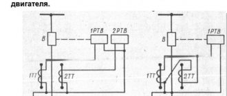
The U/D-1 connection group of the second transformer is obtained by the same double relabeling of the terminals of the two phases of the primary and traction windings of the standard transformer. The designation of the secondary winding terminals according to the factory markings is shown in the figure with the index “T”.
The same terminal of the traction winding of both transformers is connected to the rails, as in the 25 kV system (terminal st according to the factory marking). The connection with the st output rails determines that the windings on the middle rod will be the least loaded for both transformers.
By analogy with three-phase transformers in a 25 kV system, if a wire is connected to terminal at, we have a positive voltage of this wire relative to the rails, and to terminal bm, we have a negative voltage of the wire relative to the rails.
Power supply diagram for the traction network of a 2×25 kV system with a series connection of two phases of three-phase transformers (a), vector diagrams of the voltages of the primary and secondary windings (b).
The first transformer is connected by its terminal am to the contact network of the first feeder zone, and by its terminal bm to the contact network of the second feeder zone.
The second transformer has a reverse connection: with its terminal yat it is connected to the supply wire of the second feeder zone, and with its terminal bm - to the supply wire of the first feeder zone.
The sequential connection of two secondary windings of transformers with winding connection groups U/D-11 and U/D-1 makes it possible to obtain double the voltage of the two phases supplying the traction network on opposite sides of the substation.
It will be interesting➡ What is a transformer?
As above, at the contact network and the supply wire, and the voltages of the supply line are indicated, with which the voltage of the contact network and the supply wire coincide in phase. The latter are shifted by 180°. Therefore, the figure shows the position of only the contact line-rail voltages. It does not differ from the position of these vectors in a 25 kV system, if in a 2x25 kV system the transformer connected to the contact network is connected to the same phases of the supply line as in the 25 kV system.
How many rods should a three-phase transformer have?
Three-phase transformers are used to power three-phase or two-phase networks that have either a common three-phase magnetic core or two or three separate core-type magnetic cores.
According to the assembly method in modern designs for both single-phase and three-phase magnetic cores, laminated types have become predominant, as they are more reliable in operation, convenient to manufacture, and require less complex equipment and devices for assembly.
Where is a three-phase transformer used?
A three-phase transformer is used to convert voltage and is used as a device in the field of electrification of industrial enterprises and residential premises. In addition, 3-phase transformers are indispensable on ships, since they are used to power devices of various ratings.
Video: Operating principle of a transformer
Transformers can receive alternating current at one voltage and output it at another. Thus, they serve to increase the efficiency of transmitting electricity over long distances. In this video we will look at the operating principle and design of the simplest three-phase transformer device.
Video: What are star and triangle in a transformer
Three phase transformer
Parallel connection
Connecting secondary windings
Parallel connection of identical secondary windings allows you to increase the power (current) at the output of the device. This way it is possible to increase the efficiency and load capacity of the serviced line.
When using this approach, you will need to take into account one important detail related to the order of connection of the secondary windings. To obtain the expected results, the windings must be turned on in phase, which means connecting the same type of ends of all three coils at one point. If this rule is violated, the voltage at the output of two windings connected out of phase will be close to zero (the substitution principle applies). When this error is made when turning on a transformer, its power and efficiency are significantly reduced. If, during a secondary check, it is discovered that the voltage has not changed compared to a single connection, then the coils are connected in phase.
A converter device, defined as a 220 to 380 Volt 3 phase transformer, can be obtained if a special circuit is used to increase the output voltage. Its peculiarity is the presence of one primary and three secondary windings connected in a star or delta circuit.