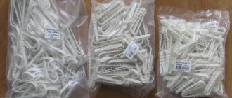
Scope of application of piercing clamps and their characteristics
These devices allow you to quickly connect to the main line, while ensuring the necessary connection conditions. A characteristic feature of such clamps is that during the installation process there is no need to remove the insulation from the SIP, which significantly speeds up the process and makes it as safe as possible.
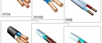
Connection using a waterproof clamp of SIP wires
The main area of application of these devices is supplying power to the consumer's distribution panel, for example, connecting a house or garage to the main trunk line. The clamp body is made of durable plastic that is resistant to ultraviolet radiation and other harmful environmental influences. The contact point itself is reliably protected from moisture. Relatively low cost, easy installation and dismantling and full compliance with regulatory requirements have made this connection method almost standard. The barbaric option for connecting to the main line - “twisting” – is now almost never seen.
Twisting is not only an unreliable, but also an unsafe connection method
Manufacturers
Leading companies producing valves are Ensto, Niled and others.
Ensto
The Finnish company Ensto produces fittings for all types of SIP. Lightweight models are available, made of plastic, as well as those made of durable alloys for harsh working conditions. A feature of the piercing clamps produced by the company is the pyramidal design of the teeth, which increases the contact area and reduces the penetration of teeth into the wire, which reduces its damage. This contact part is similar in characteristics to clamps in the form of dies.
Niled
The French company Niled is the main supplier of fittings for SIPs in Russia. A characteristic feature of the products is adaptation to local conditions. Insulation piercing devices for domestic small-section wires have been developed for the Russian market. The range of supplies meets the technical requirements of RAO UES divisions.
List of main characteristics
The characteristics of clamps of this type are determined by the following parameters:
- The number of branch SIPs that connect to the main core (usually from one to four).
- Cross-section of the main core (mm2).
- SIP cross-section (mm2).
- Maximum current load (A).
- Product weight (g).
As an example, we give a table of characteristics of NILED connecting fittings.
Characteristics of NILED connection clamps
Piercing clamps for Vulture wires: operating principle
To describe how this device works, we give an example of its design.
Design of a piercing clamp for SIP
Designations:
- A – tightening bolt.
- B – sealed housing.
- C – eye for SIP.
- D – eyelet for the main conductor.
- E – cap, placed on the end of the SIP to ensure insulation.
- F – contact pad for the main core.
- G – gear-shaped contacts for SIP.
During the connection process, the bolt is tightened; under its pressure, the gear contact knives (G) cut through the SIP insulation and ensure reliable contact. At the same time, the contact pad (F) ensures adhesion to the main core. Please note that the design of the tightening mechanism is designed in such a way as to prevent bursting. That is, the bolt “breaks” when the threshold force is reached.
Design and principle of operation
The clamps presented in stores are designed to do their job as quickly as possible; in addition, the technology of their use ensures the safety of further operation. These positive properties of SIP piercing clamps are associated with the use of high-quality materials in their design, which is associated with strict compliance with Russian and international electrical standards and constant production control.
There are several fundamental factors that you need to understand regarding the operation of a piercing clamp for SIP wire:
- It is necessary to ensure contact between the two wires. The puncture must be made between the main conductor and the counter conductor. This ensures proper operation of the entire system.
- The cores must be passed through special holes on the body of the clamping product. To do this, you need to pull back the upper bolt for connection. This operation is performed until the bolt head breaks off.
The outer part of a modern clamp for puncturing SIP wires is covered with a layer of high-quality fiberglass. The working part of the piercing device is made of durable polymer materials. This ensures that the clamping mechanism itself will be resistant to destruction under the influence of sunlight, and the housing will not allow moisture to enter, regardless of pressure and the general severity of weather conditions.
Uninterrupted quality when using clamps for SIP wires is due to their production according to modern technologies and integral quality control of the finished product at all stages of production. Based on the use of high-quality materials, the service life of a SIP puncture is about 30-40 years.
When installing branch clamps for SIP wires, you need to make punctures right through the insulation located on the conductors. Assumptions that this will serve as a negative criterion for the entire strength of the electrical installation are erroneous. Before work, you need to make sure that the place where the puncture is attached is sealed.
You should remember and take seriously the fact that the installation of the piercing clamp must be done correctly and the first time. It will no longer be possible to remove it after installation. Operating the device twice is also prohibited.
You can learn how to install the product by watching the video:
Execution options
Piercing connecting fittings are produced in two versions, depending on the functional purpose. Let's talk briefly about each of them.
A device for connecting bare and insulated wires. The design (see Fig. 4) and operating principle were described above. The main purpose is to connect SIP to power conductors or the main grounding line.
Clamps for connecting SIPs to each other. The design feature of such devices is that the contacts on both eyes have teeth that pierce the insulation. Accordingly, two bolts are used for tightening. The operating principle of the clamp is the same as the previous version. The appearance of the device is shown below.
Piercing clamp for SIP-SIP connection
Design features of clamps
The design of the piercing clamp is based on two contact plates connected to each other. There are teeth attached to them, with the help of which the insulation of the SIP cable is punctured. In this case, teeth with aluminum or copper wires create reliable contact.
The entire structure is encased in a fiberglass-reinforced polymer body. It has two recesses, precisely adjusted to the diameter of the SIP cable itself. Each recess contains contact plates. Insulation punctures are made under the influence of pressure on the housing using a bolted connection, the second function of which is to fasten the SIP cable itself in the clamp.
The connection and fastening of two self-supporting insulated wires is ensured by clamping bolts, which are used with the so-called breaking head. It provides a guarantee that the contacts will not be pinched, the housing will not crack, and the threads will not break.
Since self-supporting insulated wire is often used for laying overhead electrical lines, the clamps for them are a sealed device that provides resistance to all types of precipitation. To create complete tightness, rubber caps are additionally supplied to the device, which cover the free ends of the SIP cable protruding from the clamp
Installation of piercing clamps
The algorithm for organizing a tap using a piercing clamp is quite simple, but there are several nuances that need to be paid attention to:
- As a rule, devices of this type are designed in such a way that installation work can be carried out without turning off the power supply. That is, the tightening mechanism is isolated from the contact area. But, nevertheless, the electrician performing the connection must have the appropriate clearance group.
- To separate the core, special devices (separating wedges) should be used.
Separating wedges
You cannot use other available tools for this purpose, for example, a screwdriver, since there is a high probability of damaging the insulation. Two wedges should be installed with an interval of 20.0-25.0 cm, which allows you to separate the core from the bundle at a distance of 4-6 cm, this is quite enough for work. If possible, you can loosen the support clamp.
- The fittings are suitable for aluminum and copper conductors. It is also an ideal adapter, preventing the formation of a galvanic couple.
- It is prohibited to connect two or more self-supporting insulation insulation systems to one fitting, unless the design requires this. This prohibition is due to the fact that proper reliability and tightness of the contact will not be ensured.
- Clamps must not be reused. There are several reasons for this:
- It is impossible to determine the required clamping force, since the mechanism is “broken,” which threatens to compress the SIP above the breaking force threshold.
- the contact teeth are deformed during crimping. Consequently, when reused, they may no longer pierce the insulating coating or provide the required contact area.
- The teeth of the new clamp have a special coating in the form of silicone grease, which ensures sealing of the cut insulation. A previously used device will no longer have such lubrication; therefore, moisture will get under the insulation.
- It is imperative to put on the cut of the connected SIP the sealed cap that comes with the clamp. There are models with built-in cut sealing. Such devices are preferable, since individual parts tend to get lost; in addition, when working at height, it is inconvenient to reach into a bag every time for a sealed tip.
- To tighten the connecting fittings, use spanners (13 or 17, depending on the design of the clamp) with an insulating coating.
Dielectric spanners
Having dealt with the nuances, let's move on to the procedure:
- Lightly “release” the tightening bolt. This must be done in order not to damage the insulating coating.
- The core and SIP are inserted into the eyes intended for them. In this case, it is necessary to ensure that the cables are clearly in the middle of the clamping contacts. After this, the bolt must be tightened by hand, thereby securing the electrical wires.
- Holding the clamp from the bottom, the bolt is tightened using a spanner wrench (usually 13).
- You need to tighten it until the bolt “breaks”. This indicates that the required clamping force has been achieved.
Installation errors
Installation of SIP: requirements and stages
When installing SIP using piercing clamps, the following is not allowed:
- Re-install and tighten the piercing clamps, since the head is disposable and the next time a reliable fastening will not work.
- Connecting the branch cores to each other using piercing clamps.
- Installation of more than one core into one terminal (unreliable contact).