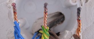
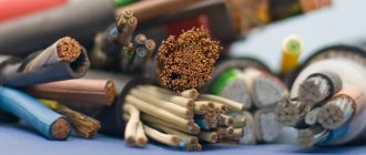
One of the common causes of fires is faulty electrical wiring. Fires occur due to insulation failure or heating of cable cores at connection points (sockets, switches or junction boxes).
Poor contact leads to the appearance of a large contact resistance, which generates heat. This destroys the insulation, causing a short circuit and fire.
Therefore, obtaining a reliable, high-quality connection of copper conductors is a prerequisite for the safe operation of any household electrical appliances.
Using an inverter
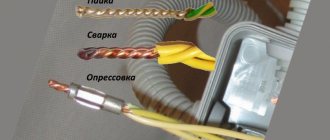
Copper wires, most common in residential buildings, are connected in several ways, but welding is considered the most reliable.
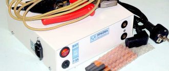
As a result of this connection, a homogeneous conductor is obtained, which ensures complete fire safety. Welding is carried out with direct or alternating current voltage from 12 to 36 V, and the welding current must be adjusted. Most welding inverters meet these requirements. They produce a special apparatus for welding copper wires, which is used by electricians. It has a power range of 1-1.5 kW and welding current adjustment in the range from 30 to 120 A.
Unlike conventional inverters, the equipment has less weight and dimensions; in addition, the ends of the welding cables are equipped with a special holder for carbon electrodes and a clamp with a large clamping surface for the conductors. If the farm already has an inverter welding machine, then you don’t need to buy a special device for welding copper wire.
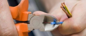
For convenience, pliers and an electrode holder are welded to the welding cables or attached through a bolted connection. Any powerful clamp can play the role of a carbon electrode holder. Its handles must first be insulated.
The pliers are attached to the ground wire. They will hold onto the twist of the copper conductors being welded, while they will perform the important function of heat removal. This is necessary to protect the insulation from exposure to high temperatures.
Connecting wires by crimping
The crimping method is widely used to make reliable connections in junction boxes. In this case, the ends of the wires are stripped, combined into appropriate bundles and pressed. The connection after crimping is protected with electrical tape or heat shrink tubing. It is one-piece and does not require maintenance.
Crimping is considered one of the most reliable methods of connecting wires. Such connections are made using sleeves by continuous compression or local pressing with special tools (press jaws), into which replaceable dies and punches are inserted. In this case, the wall of the sleeve is pressed (or compressed) into the cable cores to form a reliable electrical contact. Crimping can be done by local pressing or continuous compression. Continuous crimping is usually done in the shape of a hexagon.
Before crimping, it is recommended to treat copper wires with a thick lubricant containing technical petroleum jelly. This lubrication reduces friction and reduces the risk of damage to the core. Non-conducting lubricant does not increase the contact resistance of the connection, since if the technology is followed, the lubricant is completely displaced from the contact point, remaining only in the voids.
For crimping, manual press pliers are most often used. In the most common case, the working parts of these tools are dies and punches. In general, the punch is a movable element that produces local indentation on the sleeve, and the matrix is a shaped fixed bracket that perceives the pressure of the sleeve. Dies and punches can be replaceable or adjustable (designed for different cross-sections).
When installing ordinary home wiring, small crimping pliers with shaped jaws are usually used.
You can, of course, use any copper tube as a sleeve for crimping, but it is better to use special sleeves made of electrical copper, the length of which corresponds to the conditions for reliable connection.
When crimping, the wires can be inserted into the sleeve either from opposite sides until mutual contact is strictly in the middle, or from one side. But in any case, the total cross-section of the wires must correspond to the inner diameter of the sleeve.
Process modes and features
Due to the limited welding currents, devices for fusing electrical wires can have very small sizes. Thermite welding of wires, which is widely used among specialists and is organized using a special powder mixture, makes it possible to further simplify the welding procedure. In this case, it is possible to significantly reduce the dimensions of the portable equipment used.
When carrying out ordinary electrical operations (including welding copper and aluminum wires), special equipment is used, which uses direct current of direct polarity to form an arc. The plus of the supply circuit is connected to the electrode holder in such a device, and its minus is connected to the grounding wire, which is usually called “ground”.
When welding with certain types of copper-coated electrodes, reverse polarity is used.
The magnitude of the welding current in any case is determined by the dimensions of the electrical wire harness being installed and the cross-section of the individual cores collected in it. During the welding process, the required value of this parameter is set using a regulator located on the control panel.
Various models of small-sized welded units provide adjustment of the output voltage. Some manufacturers and even home craftsmen further improve the design of their models by installing special current limiters in them. Data on the output parameters of such devices can be found in the tables of the dependence of the operating voltage and current on the cross-section of the wires being welded and their number in the twist.
Pros and cons of welding, its varieties
The advantages of connecting wires by welding are the absence of transition resistance, which is always present in twisted or bolted connections. This is especially true when laying wiring for powerful devices. The disadvantages are the need to buy or make your own welding machine designed for twisting.
Welding work requires some skills, so the electrician who will weld the strands needs to learn at least the basics of this craft.
When performing electrical installation work in production, various types of welding are used: standard, arc spot, plasma, torsion, electron beam, ultrasonic, or various combinations thereof. For domestic use, electricians most often use a device for spot and arc welding, which operates on carbon or graphite electrodes.
This solution allows you to obtain good quality connections at a minimum cost of the necessary devices and components. When making a wire welding machine, most attention should be paid to the following characteristics of the device:
- The current strength that the device can produce. Ideally this is a variable value.
- The voltage produced by the device is sufficient to cause an electric arc - usually 12-32 Volts.
- What kind of current does the welder use - alternating or direct? If you have experience in such work, you can use variable, but for beginners it is strongly recommended to start with constant.
Since welding different metals requires different currents and voltages, universal welding machines can necessarily adjust these values. In addition, when joining different materials, you may need special fluxes that will protect the metal from oxidation or the penetration of gases from the air into it. Most universal-purpose welding machines are quite bulky and heavy, but for small welding jobs you can find inverter welders for a relatively low price that are ideal for welding wires.
If you are welding copper wires that are used in home wiring, there is no need to use very high current and voltage, so it is possible to use small-sized welding machines that fit into a standard tool case.
About the designs of welding transformers
For welding with twisted electrical wiring, you can use various industrial equipment or make it yourself.
Inverter devices
These modern industrial devices allow you to perform high-quality work, creating good seams even for novice welders.
It’s not at all difficult to buy an inverter for welding in a store. They can also do other chores around the house. But we do not pursue this goal, but are interested in equipment that can be made with our own hands.
Homemade designs
Among the many developments, we will consider two: the simplest and the most powerful, which are not so difficult to implement.
The simplest welding machine
It can be made to replace electrical wiring in a private house or apartment: you just need to select or make a transformer with a power of about 600 watts with a voltage of 220/12÷36 volts.
Strand welding may require a current of about 100 amperes. Considering that the operating mode lasts no more than two seconds, and the arc for each circuit is created with a time delay, the thickness of the wire for the secondary winding and the electrode connection circuit can be selected for smaller loads. Overheating of their insulation will have to be prevented by blowing or interruptions in work.
Where to get a voltage transformer
From ready-made samples, we can recommend a model of the TBS type (armored machine-tool transformer).
An alternative method is to make it yourself. This technology is described in detail in an article about the Moment electric soldering iron.
The only difference is that there is no short-circuited secondary winding. It can be wound not with a solid bar, but with a parallel set of available wires with a cross-section of 2.5÷3 mm square. A minimum voltage of about 12 volts will be sufficient for welding copper, but it is advisable to increase it by 2–3 times.
Design of a device for welding twists
Such a device is not difficult to make with your own hands. It greatly simplifies the work and makes it safer.
The carbon electrode is mounted on a fixed metal base.
The twisted wire is simply inserted into the thumb clamp of a movable metal arm and pressed against a graphite flux electrode (borax). Voltage is briefly applied to the transformer to carry out welding. The wires are allowed to cool right inside the electrode recess.
You will need to experiment to determine the welding time by trial and error, using scrap pieces of wire to create additional twist.
Powerful DC Regulator
It is manufactured in a separate body, consisting of two blocks:
- electronic;
- power
They are connected by wires to each other and leads from the secondary winding of a separate power voltage transformer, as well as welding electrodes.
This regulator produces rectified current, which can be used for welding and other purposes, for example, charging batteries, parallel powering the starter when starting a car engine, or performing other work.
The structure is easy to assemble using the hinged method. Even in this case, you can achieve its small size.
The regulator receives power from the secondary winding of the power transformer. The input voltage can be within 50÷90 volts.
The electronic unit
The work is based on the circuit of a phase-pulse signal generator made of two bipolar transistors of direct and reverse conduction (pnp and npn type).
The position of the potentiometer R2 slider affects the charging rate of capacitor C1 to a voltage of 6.9 volts. When it increases, transistors VT1 and VT2 open. Through them, the discharge of the capacitor begins on winding I of transformer T1 (pulse type).
This discharge pulse, through the secondary windings II and III, enters the control electrode of the power thyristor VS-3 or VS-4, opens it with the corresponding direction of the half-wave of the sinusoidal voltage harmonic.
Thyristors VS-1 and VS-2 operate as intermediate control current amplifiers for the power circuit. The fact is that three-winding transformers of the TI-3÷TI-5 series are used as pulse ones. In all three windings they have the same transformation ratio (1:1:1). The pulse current they create is small; it needs to be increased.
The same issue can be solved differently: assemble a pulse voltage transformer on ferrites with an increased transformation ratio in the secondary windings, achieving a current value sufficient to control the output stage of the main thyristors.
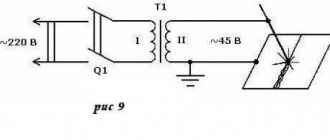
The principle of operation of arc welding - device diagram
Since welding requires a large current, the basis of any welding machine is a step-down transformer - a loss in voltage is always accompanied by a gain in current and vice versa. A standard diode bridge is used to convert alternating current into direct current, and a capacitor is used to smooth out ripples.
A noticeable disadvantage of using a direct current device is that the diodes and capacitor used are rather large and they significantly increase the weight of the welding machine, which is initially made portable.
Experts also recommend installing additional resistance at the input or output of the diode bridge, since diodes “do not like” a short circuit in its pure form.
Many craftsmen manually assemble a welding machine for welding copper wires, which produces an arc from alternating current and use them successfully. Therefore, it is impossible to say unequivocally that it is necessary to use a direct current device - everyone chooses the necessary model according to their skills. If an AC welding machine is manually assembled, then the diode bridge and capacitor are simply thrown out of the circuit.
A necessary skill that you will have to master to use an AC welding machine is to learn “by eye” to determine how long you should hold the ignited arc of the electric discharge so that the end of the twist heats up and fusions.
The most common way to make a negative contact for welding is with old pliers that hold the wires.
For the phase, take a clamp that can hold the graphite rod. The design of the clamp can be very diverse - from a screw connection to the so-called “crocodiles”, both home-made and factory-made. To connect to the welding machine itself, cables with a cross-section of about 10 mm² are used.
Despite the fact that a device assembled in an industrial environment is an order of magnitude more expensive than a homemade one, its price is not exorbitant and allows you to purchase such a welding machine even on a limited budget. The advantages of its use are obvious - it is a precisely calculated design with a current regulator, which allows you to work with different types of metals and the number of wires being welded.
Features of wire welding
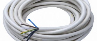
First you need to make the correct installation of the wiring - choose its optimal diameter, correctly position it in the walls of the room. To distribute lines, special boxes are installed. There it becomes possible to redirect the supply of electricity from the central wire to the auxiliary one.
Welding wires in a box has the following nuances:
- Use of inverter welding machines with power up to 1 kW. These can be factory models or homemade ones.
- Electrodes - graphite or carbon. It is not recommended to use copper-plated rods, as this may affect the quality of the connection.
- Unlike soldering, no flux or other types of additives are required during welding.
- Wire heating temperature control. Otherwise, there is a high probability of partial destruction or change in the properties of the insulation.
Work is carried out only when the network is completely de-energized; a protective mask and special work clothing are used during welding. The diameter of the electrodes depends on the calculated current strength, which, in turn, is calculated depending on the diameter of the cores and their number.
Twisting. Twisted connection of wires.
Twisting of bare wires as a connection method is not included in the Electrical Installation Rules (PUE). But despite this, many experienced electricians consider a correctly performed twist as a completely reliable and high-quality connection, arguing that the transition resistance in it is practically no different from the resistance in the whole conductor. Be that as it may, good twisting can be considered one of the stages of connecting wires by soldering, welding or PPE caps. Therefore, high-quality twisting is the key to the reliability of all electrical wiring.
If the wires are connected according to the “as it happens” principle, a large transition resistance may arise at the point of their contact with all the negative consequences.
Depending on the type of connection, twisting can be performed in several ways, which, with a small transition resistance, can provide a completely reliable connection.
First, the insulation is carefully removed without damaging the wire core. Sections of cores exposed to a length of at least 3-4 cm are treated with acetone or white spirit, sanded with sandpaper to a metallic shine and tightly twisted with pliers.
Features of welding aluminum wires
The use of aluminum cores is prohibited by the current PUE. But in some older homes you can still find this type of wiring. A complete replacement entails financial costs and can take a long time. But for welding aluminum wires it is necessary to take into account a number of specific points.
They are as follows:
- cleaning contact parts from oxide film;
- use of special flux for aluminum welding;
- treating the welding area after cooling with quick-drying varnish.
The use of mechanical types of connections for aluminum wires is not recommended. Also, you cannot twist wires made of this material with copper ones. To do this, use special adapters.
Selecting Electrodes
In addition to the welding unit, for electrical work you will need special electrodes suitable for the selected wire processing mode. Most often, copper rods of a special design with graphite or coal additives are used for these purposes.
To obtain a high-quality and reliable connection during its formation by electric welding, special filler and activating additives (fluxes, in particular) are necessarily used. In addition, this will require the following auxiliary and consumable materials:
- insulating tape;
- well-sharpened mounting knife;
- side cutters or pliers.
After preparing a complete set of tools, you can safely begin welding activities.
Alternative connection methods
It is not always possible to weld current-carrying conductors. Difficulties are caused by the lack of an inverter (welding machine) or insufficient experience in performing this type of work. In this case, it is recommended to consider alternative wire connection options.
Methods for forming reliable contact between several cores:
- Twisting (crimping). It differs from the process described above in the absence of a welded joint. It is not recommended to do this, since there is a high probability of lack of direct contact between several wires, which can lead to a resistive effect - heating.
- Soldering. Unlike welding, solder and flux are used. They should fill the space between the twisted wires. Convenient for connecting small cross-section cores.
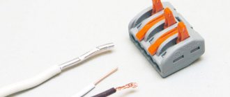
- Contact clamps. They can be screw or mechanically fixed. The former are used for switching a large number of wires. Mechanical fixation is recommended for connecting large diameter cores for networks with a high load rating.
For each technique, an individual procedure for performing work is adopted. But in any case, generally accepted safety rules are followed.
Preparing the connection
Unlike traditional methods of welding workpieces, which involve the formation of a seam joint, welding of conductors inside a junction box is possible only after they are twisted.
Before welding the twist, the ends of each wire must be thoroughly stripped. The outer insulation from the wires should be removed by 7-10 cm, which ensures a convenient length for the twist being formed. .
The length of the bare parts obtained after stripping, according to the requirements of the PUE, should be about 5 cm, which eliminates excessive heating and melting of the wires during the welding process.
To better understand the features of welding wires with your own hands, it is advisable to familiarize yourself with the rules for choosing the equipment used. To do this, two important questions need to be considered: what types of welding equipment are applicable in the given conditions, as well as which welding electrodes are optimally suited for the stated purposes.
Types of electrodes
Round
The simple “round” type can be used indefinitely. The cross-section of the rod ranges from 3.2 to 19 mm. There are also so-called “round endless” electrodes. Of course, they have strictly limited sizes. However, the efficiency fully justifies the main name.
The diameter of the “endless” elements varies from 8 to 25 mm. Most often they are used when welding using a special machine. Both options are acceptable for “simple” welding work. However, any types of coal models, due to their infusibility, consume little.
There are also several types of such electrodes that deserve separate analysis.
Semicircular
The semicircular electrode usually has a diameter of 10 to 19 mm. Such products are often recommended for cutting metal workpieces. It is semicircular electrodes that are used by most amateur and professional welders. The seam has an optimal shape. Creating an edge with a semicircular electrode is easy.
Rectangular
They are also sometimes called flat - but not everything is so simple. When traders say the word “flat”, they may also mean square. The section size ranges from 8 to 25 mm. Most often, such tools are used when it is necessary to repair a defect in a steel casting. They are rarely used for other purposes.
Hollow
It is not often possible to find this type of electrodes. Their typical size ranges from 5 to 13 mm. It is this solution that is suitable for forming U-shaped outline lines. Hollow structures are also excellently used for vacuum welding. The pressure in the working chamber should not exceed 665 Pa.
Graphite electrode for welding
Due to its technical characteristics, the graphite electrode is easy to cut, consumes more slowly, and does not crack during welding. As practice shows, welding of wire cores is carried out in distribution boxes. The boxes are located quite high, so you will need to use portable welding equipment for welding.
Industrial devices are used for these purposes, the use of which is advisable in a professional sense. If possible, you can assemble the welding machine yourself. However, for most people, inverter-type devices, which are presented in a large assortment in stores, are perfect. They are compact, mobile, lightweight and also have the ability to adjust the welding current you need.
Types of electrodes for welding copper wire cores
When welding copper conductors, appropriate electrodes must be used. We have already mentioned carbon electrodes. There is also a graphite type of electrodes. Battery rods, brushes of commutator motors and similar products made of graphite can be used as an electrode in household use.
Graphite rods are a good replacement for purchased electrodes, with the only exception that they do not have copper plating, but this can be solved by improving the holder. To do this, it will be necessary to use an alligator clip, both for the electrode and for the ground connection. They will not be as bulky as standard ones, so it will be more convenient for you to work in switchboards. Of course, you will need to take care of additional insulation of the handles.
Graphite and carbon electrodes have a general similarity: both have a melting point 4 times higher than the melting threshold of copper itself. Because of this property, the consumption of electrodes when connecting electrical wiring is very low.
Please note that the electrode heats up to a high temperature instantly, so there is a risk of overheating the material being welded, which, in turn, can damage the insulation in the cable. The welder needs to know these factors in order to be careful when installing electrical wiring.
Differences between graphite and carbon electrodes
Despite the similarity of graphite and carbon rods when installing wiring, their characteristics differ:
- The first difference is the price. Graphite products are more affordable;
- if the carbon rod is completely black, then the graphite electrode has a gray-dark color with a metallic tint;
- welding using a carbon electrode requires a certain skill from the welder, since the carbon rod creates an arc of enormous temperature, which can lead to the destruction of the welded twist. At the same time, huge temperature indicators occur at low current. Based on this, carbon electrodes will be useful to a welder with a weak welding machine;
- for those who own an inverter device that is equipped with a current regulator, it is better to use graphite rods. When working with them, less skilled craftsman is required. In addition, the connection of wire cores after their use is characterized by greater strength, better quality, and increased resistance to oxidation than after the carbon welding process.
What equipment is needed for welding copper wires?
To weld prepared copper cables you will need an inverter and electrodes.
Features of copper: fluidity, high thermal conductivity, ability to absorb gases - require experience and skill from the performer.
Electrodes used
For welding copper wires, two types of electrodes are used: carbon or graphite with a copper coating:
- the destruction temperature of the electrode material is more than 3800ºС, and copper melts at 1080ºС, which allows their repeated use;
- rapid heating of the rod material to the copper liquefaction temperature;
- During welding, the carbon rod does not stick to the wires;
- 5-10 A is a sufficient, although small, current for a stable arc discharge.
Features of using carbon electrodes
The electrodes are made from black electrical carbon pressed into a rod shape. Its ends are beveled. Even with a very low welding current, a high temperature occurs at the tip of the electrode.
A carbon electrode is used when it is not possible to weld with a graphite element. You need to work very carefully to prevent the insulation from overheating. Carbon electrodes are commonly used in low power welders.
When working with carbon electrodes, the following features must be taken into account:
- the welding site is fragile , can oxidize and have a porous structure;
- Due to the high arc temperature, the electrode is consumed faster;
- It is more difficult to work with a carbon rod electrode than with a graphite electrode ; practical skills are required.
Approximate cost of carbon electrodes on Yandex.market
Graphite welding electrodes
Graphite electrode rods are gray in color with a slight metallic tint. The crystalline structure of carbon is not subject to oxidation. When welded, crystalline graphite forms a corrosion- and temperature-resistant compound. These electrodes are advantageous to use and are cheaper than carbon electrodes. The rods do not crack and last a long time.
If necessary, it is possible to replace it with improvised graphite products - brushes from commutator motors, rods of disassembled batteries. In the case of using a readily available graphite replacement without copper plating, an alligator clip is used instead of a conventional holder.
Approximate cost of graphite electrodes on Yandex.market
Graphite electrodes are more often used with inverters that regulate the welding current.
Inverters
For welding, a DC or AC device with a voltage in the range of 12-36 V is suitable; current adjustment is required.
The choice of model is based on the intended modes of use of the device: from half-hour work without a break to many hours of intensive work.
If the device will be used infrequently, then a model that provides a maximum welding current of 150 A and a power of about 500 W is suitable. This is enough for welding strands with a cross-section of 20-25 mm².
Approximate cost of inverters for welding on Yandex.market
Assembly instructions
Assembling the device with your own hands will require minimal skills in working with hand tools. For convenience, the manufacturing process should be divided into 5 stages:
- Preparing the body. It is selected based on the dimensions of the transformer.
- Search and installation of a transformer. Checking its performance.
- Selection of power cable. Protection of the device from overload.
- Installation of output terminals. Other connection methods.
- Selection and installation of holder and electrode. DIY alternatives.
Welder body
The easiest way is to use a ready-made housing from any electrical device. For example, from a car charger or a suitable uninterruptible power supply from a computer. It is desirable that the housing be made of dielectric material (plastic, carbolite). This will be a plus in favor of the security of the future device. If none of the above options is suitable, then the easiest way is to make a body from thin sheet iron 1-3 mm thick.
Transformer selection
The required transformer can sometimes be found in stores. Another option is to look for it from friends or wind it yourself.
The primary winding of the transformer is designed for 220 V. The iron is selected based on the overall power of 200-1000 W. Low-power transformers are suitable for welding thin wires, and high-power transformers are suitable for thick ones.
The secondary winding of the transformer is wound with wire from 35 kW. mm, because she will have to experience short circuit currents. It is better to use copper as the material for the output winding. This will reduce heating losses.
Power cables
The 220 V power supply cable is selected based on the power of the transformer. For devices with a consumption of 1 kW, its cross-section is taken to be at least 4 square meters. mm. A thick cable is also better because it is more difficult to break or break during repairs and wiring.
To protect the device, it would be useful to install a fuse or circuit breaker in the primary winding circuit. This way the transformer will be protected from overcurrent.
Terminal Applications
If possible, the use of terminals should be avoided. They tend to become loose and burn over time, especially at high currents in the secondary winding of the transformer. The most reliable connections are made by welding, soldering or crimping.
In some cases, terminals are convenient. For example, at the output of a welding transformer. Using terminals, you can move the device separately from its wires. The main thing is to ensure that during operation the terminals do not oxidize, dangle or overheat. It is permissible to periodically remove dirt using a file.
Electrode holder
Welding is carried out with a graphite electrode coated with a thin layer of copper. This combination provides the good conductivity of copper combined with the heat resistance of graphite. Similar electrodes are commercially available. If you couldn’t find them, you can make them yourself from a graphite brush of an electric motor. It should be taken larger and cut with a hacksaw to the desired size.
Homemade holders for welding. The holder is made of a pair of copper bars and bolts for tightening. The device must securely clamp the graphite electrode.
Recommended welding current modes for different conductors
The magnitude of the welding current depends on the cross-section size and the number of strands in the twist: the thicker the twisted bundle, the greater the current value must be set on the welding machine:
- 2 cores, cross section of each 1.5 mm² - 70 A;
- 3 cores, cross section of each 1.5 mm² - 80-90 A;
- 2-3 cores, cross section of each 2.5 mm² - 80-100 A;
- 3-4 cores, cross section of each 2.5 mm² - 100-120 A.
The specified welding current modes are indicative. Wires from different manufacturers differ in chemical composition and declared cross-section, and welding devices also differ in their characteristics. Therefore, it is better to select the value of the welding current practically on a small section of the same wire. When choosing a mode experimentally, the optimal one will be when the arc is stable and the tip of the electrode does not stick to the welding site.
For modern inverter-type devices:
- stable welding discharge, ensuring high-quality welding work;
- When welding, liquid metal does not splash;
- the arc does not blind the welder due to the low melting point of copper;
- inverters are not heavy, their dimensions are small, which allows them to be carried to the installation site on a belt.