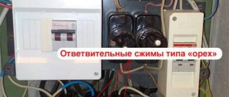
Types of wire connections.
Connections of wires and cables in spans of power lines may only be made using special clamps, and in each span when installing the line there should be no more than one connection for each wire or cable. Connections of overhead line wires are made either using oval connectors - by crimping or twisting methods, or with shaped connectors - by crimping method. Connections of wires and cables using bolted clamps in line spans are not used. Single-wire steel wires may be joined by lap welding, and the length of the weld must be at least 10 wire diameters. After completion of the weld, the welding site must be reliably protected from corrosion by thorough cleaning and coating with moisture-resistant paint or ZES lubricant.
Experience in using spiral reinforcement on overhead lines
Ryzhov S.V., JSC Elektrosetstroyproekt Introduction
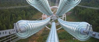
Spiral reinforcement, as a new type of reinforcement for hanging wires of overhead power lines, appeared relatively recently, in the 50s of the 20th century. It is based on the principle of transferring force from a flexible thread to a cylinder, known since the time of Euler, applied to a wire spiral enveloping a wire.
Strengthening and protecting the wire with spiral wire winding began to be practiced when the first damage to the wires began to be detected on overhead lines (which, as it later turned out, arose due to vibration caused by the wind), Fig. IN 1. Thus, spiral reinforcement was actually a combination of the idea of protecting wires with preformed spiral strands with the Euler principle of transferring tension from the wire to the clamp through a spiral, or more precisely, through a spiral pinching.
Since the late 50s of the last century, spiral reinforcement as a new method of terminating wires (as well as cables, communication cables, antennas, etc.) has become increasingly used in developed countries of the world.
In Russia, an urgent need for spiral-type fittings arose with the beginning of mass construction of communication lines with fiber-optic cables in the 90s of the 20th century. Although spiral reinforcement was already widely used abroad for hanging wires of overhead power lines, it was not produced in Russia and was practically unknown.
It should be especially emphasized that there is practically no information about the operating principles of spiral reinforcement, since it is the internal “know-how” of the companies producing it. There are only indirect indications in patents. And even more so, one can only guess about production technologies, standards, raw materials, etc.
The main differences and advantages of spiral-type fittings compared to well-known structures traditionally used in communications and energy are the following:
- it allows you to secure fiber-optic communication cables that cannot be secured by any other technical means;
- reliably protects wires (cables and optical cables) from the effects of crushing loads in places where clamps are installed (tensioning, supporting, repair and connecting) due to the uniform distribution of compressive force along the length of the spiral clamp;
- provides reliable fastening and protection of wires (cables and optical cables) from dangerous bends, abrasion, vibration and other mechanical influences, increases their service life;
- combines very well with wires, cables, ropes, since it itself is flexible and, after installation, actually integrates with them into a single whole;
- allows for prompt repair of wires (cables) with almost any type of damage, until their mechanical and electrical characteristics are completely restored;
- in many cases, there is no need to lower the wire to the ground, to deliver press equipment to the work site, etc., which can significantly reduce the time and cost of repair work; installation is carried out without the use of special equipment and accessories and does not require highly qualified line personnel;
- the use of spiral reinforcement significantly simplifies and speeds up both repair and restoration work on existing lines and the construction of new lines.
In the early 90s, massive construction of overhead optical communication lines began in Russia.
This fundamentally new market segment required the creation of domestic production of spiral reinforcement in Russia. The primary urgent task for Russia has become the issue of developing a set of problems associated with the production of spiral reinforcement, and work on creating new designs of spiral-type reinforcement. In 1991, it was created, and already the first developments carried out in 1992-1996 made it possible to ensure the rapidly expanding mass construction of overhead optical communication lines in Russia, relying on the domestic manufacturer of spiral fittings, at prices significantly lower than foreign supplies at comparable quality.
In subsequent years, scientific research aimed at improving the designs of spiral fittings, improving the technology of its production, and expanding the range of products and components made it possible to increase production volumes hundreds of times and almost completely meet the need for this fittings at Russian enterprises for the installation and operation of optical communication lines. At the same time, work was carried out to introduce spiral reinforcement into traditional energy, both during the construction of new lines and during work related to operation and repairs.
Currently, JSC Elektrosetstroyproekt is the only enterprise in Russia and the CIS countries specializing in the development and production of spiral fittings for optical cables of overhead communication lines and wires of overhead power lines. The fittings are widely used for hanging and repairing both bare and insulated wires, self-supporting optical cables and lightning protection cables, including those with built-in optical cables, on the supports of overhead power lines, railway contact networks, urban surface electric transport and street lighting.
Below are examples of the use of CA for suspension and repair of both fiber-optic communication lines and overhead power lines.
Repair of AC 300/39 wire on the 500 kV overhead line “Yuzhnaya – Cherny Yar” (MES CENTER).
On the 500
kV
Yuzhnaya – Cherny Yar overhead line in 1999, significant damage to the AC 300/39 wire was discovered in a number of spans in the places where paired spacers were installed.
In some places, the outer and inner conductive layers were completely destroyed and deformed over a length of up to 2.0-2.5 m
;
the steel core is exposed over a length of up to 0.5 m
. In Fig. 5.1. a fragment of the damage is shown.
Rice. 5.1. Fragment of damage to the 500 kV power line “Yuzhnaya – Cherny Yar”
According to existing standards, if the aluminum cross-section of the wire is damaged by more than 34%, it is necessary to cut out the damaged area and make an insert using two connecting clamps.
Obviously, the most acceptable in all respects would be repairs carried out without lowering the wires and without disturbing the sag, which also does not require the delivery of bulky and heavy press equipment to the wire. It is precisely these requirements that the repair of wires with the use of repair connecting spiral clamps of the SS type meets. Spiral clamps SS-24.0-21 were used for repairs. In October 1999, supervision of installation of clamps in the span between supports No. 59 and No. 60 was carried out. Damage in the indicated area was located in three places on the mid-phase wires: in the middle of the span and at a distance of 5060 m
from the supports at the ends of the span.
The design of the SS-24.0-21 clamp includes 2 sets of conductive spirals made of ABE aluminum alloy wire, and a set of strands of protector-clamp spirals made of galvanized steel wire. Sets of conductive spirals are wound over the aluminum layers of the wire being repaired and restore its electrical conductivity. The retaining protector is mounted on top of the conductive spirals and ensures both the reliability of the electrical contact of the conductive layers and the mechanical strength of the wire. The last circumstance is very important, since during the operation of a wire repaired using CC type clamps, a gradual redistribution of the load occurs between the steel core and the aluminum layers.
The repair was carried out from a mobile telescopic tower using standard installer hand tools: side cutters and a screwdriver.
The installation of the clamps was carried out in the following sequence: the wires of the upper layer of the wire were unraveled and bitten out at a length of 0.5 m
in one direction and the other from the middle of the repaired area (that is, at a length of 1.0
m
, which corresponds to the length of the spirals of the lower conductive layer of the clamp). The torn wires of the lower layer were straightened and, as far as possible, placed into the wire layer. The laid layer was cleaned with a metal brush and then a generous layer of protective conductive lubricant was applied. Spirals of the lower conductive layer of the clamp were mounted on top of the lower layer of the wire. The spirals of the upper conductive layer and the protector-fixator were mounted in the same way.
The main factors complicating the installation were the large length of the damaged sections and significant deformation of the surviving wires of the external and internal conductive layers of the wire. In this regard, the installation time also increased significantly, since up to 50% of the time was spent on straightening the wire layers and laying them. Due to the large length of the damaged sections, in two cases it was necessary to use two sets of clamps simultaneously, installing them with partial overlap (shift). The repair time for each of the damaged areas, depending on their complexity, ranged from 40 to 70 minutes. The appearance of the repaired sections of phase wires is shown in Fig. 5.2.
Rice.
5.2. Restored section of the line Repair of the optical lightning protection cable on the 110 kV Kaluga-Balabanovo overhead line.
In Figure 5.3. a fragment of damage to an optical lightning protection wire with a built-in optical cable (OPGW) is presented.
a) b)
Rice. 7.3. Fragment of damage to OPGW from a lightning strike As a result of a lightning strike in the summer of 1999, the upper aluminum layer of OPGW was burned down to the steel inner layer, which protects the plastic tube with the optical module.
In Figures 5.4. and 5.5. the stages of restoration of the conductive layer OPGW using spiral repair clamps RS-15.4-01 are shown.
The clamp kit includes two layers of spirals. The bottom layer is made of aluminum alloy ABE and is designed to restore conductive properties. The upper layer of the spirals is made of galvanized steel wire; it gives tight contact to the spirals of the lower layer.
a) b)
Rice. 5.4. Installation of spirals of conductive layer of repair clamp RS-15.4-01
a) b)
Rice.
5.5. Installation of a protector-retainer (a) and repaired section of OPGW (b) Repair of the river crossing. Ob 500 kV overhead line "GRES-2 - Pyt-Yakh" (JSC Tyumenenergo).
On the 500 kV overhead line "GRES-2 - Pyt-Yakh" at the crossing of the river. Ob near Surgut (span length 963 m
) for a number of years there have been problems with damage to the TK 141 lightning protection cable in the supporting clamps. The applied vibration protection schemes using standard Stockbridge vibration dampers did not give the desired result: within a year the dampers were completely destroyed, and in the second year of operation the cable was damaged. After replacing the cable everything happened again.
In March 1998, the crossing was equipped with protective protectors and vibration protection circuits using multi-frequency vibration dampers of the GV type (manufactured by JSC ESSP) and loop vibration dampers. The vibration protection diagram for the TK 141 cable is shown in Figure 5.6. To reduce bending stresses, a protective protector PZS-15.4-01 was installed at the area where the cable exits the boat. The proposed scheme works efficiently and reliably. To date, no damage to the cable or vibration dampers has been detected.
Connecting wires with oval connectors.
The most common method of connecting wires in spans of lines is using oval connectors. When connecting wires with oval connectors, electrical contact is obtained both as a result of direct contact of the surface of individual wires of the outer layers of the ends of the connected wires inserted into the connector with an overlap, and through the connector body due to the contact of the wires of the outer layers of the ends of the wires with the inner surface of the connector body. When connecting steel-aluminum wires, an aluminum spacer is installed between them to equalize the crimping forces, and the contact of the surfaces of the connected ends of the wires occurs through the spacer. Thus, in wire connections made with oval connectors, the current flows primarily from wire to wire and only partially through the connector body and spacer, if installed. The oval connector is an oval tube made of aluminum or steel. The tube is flared at both ends. To connect wires of different brands, the following brands of oval connectors are produced: SOAS - for connecting steel-aluminum wires; SOA - for connecting aluminum wires; SOS - for connecting steel wires. A mark is applied to the body of each connector at the factory indicating for which wire the connector is intended, for example: SOAS-70 - oval connector for steel-aluminum wire AS-70. Oval connectors are used to connect steel-aluminum and aluminum wires with a cross-section of up to 185 mm2, copper wires with a cross-section of up to 150 mm2 and stranded steel wires with a cross-section of up to 95 mm2.
SIP-3 connection in loops
The choice of such piercing clamps is very wide and is presented on the market by different manufacturers.
NiledSicamEnsto
Niled RP150, 240
Sicam TTDC
Ensto Sliw17.2
On top they are equipped with two tightening bolts with a shear head. The most reliable way to remove the head is to use a spanner.
To connect protected SIP-3 wires with bare wires of AC grades, connecting branch clamps of a different design should be used. They have piercing teeth located on one side only. On the other hand, there is a smooth surface like an ordinary die.
NiledSicamEnsto
Niled RPN150
Sicam NTDC
Ensto Slip 32.2
Be sure to brush the bare, bare wire before installing the clamp.
If you do not have sealed punctures available, you can use other die clamps. For example SLW25 from Ensto.
The clamp itself is filled with a conductive anti-oxide lubricant, which improves contact and prevents moisture from getting into the connection.
To protect from moisture from the outside, the die is covered with a special casing, which is made of plastic resistant to ultraviolet radiation.
Preparing wires and connectors for installation.
The first technological operation performed when connecting wires in any way is the preparation of wires and connectors. Before installing the connector, the necessary materials and tools must be prepared, namely: a steel brush, a steel card brush, pliers, a triangular file, a hacksaw with blades or a cable cutter, bandage wire, ZES lubricant or technical petroleum jelly, gasoline and clean rags or rags. The operational reliability of the connection to a very large extent depends on how thoroughly the necessary processing and cleaning of the connected ends of the wires and the contact surfaces of the connector is carried out. The connectors must be cleaned of dirt and grease; their inner surface is cleaned with a rag soaked in gasoline, and then lubricated with ZES grease or technical petroleum jelly. After lubrication, the inner surface of the connector is treated with a steel brush until it shines to remove the oxide layer, then wiped with a clean, dry cloth and lubricated again with a thin layer of lubricant. The ends of the wires to be connected must be oriented so that they can be freely inserted into the connector. Then the ends of the wires are cleaned of dirt with a rag soaked in gasoline, lubricated with ZES grease or technical petroleum jelly, cleaned with a card brush until shiny, wiped with a dry, clean rag and then lubricated with a thin layer of lubricant. This completes the preparation for connecting the ends of the wires and the connector. It should be noted that ZES lubricant provides protection of the joint from corrosion for a very significant time, since it has a dropping point above 105 ° C and very weak oxidation, while the protective effect of technical petroleum jelly is limited to several hours or days, depending on the time of year and the temperature of the joint. The given procedure for processing wires and connectors must be strictly observed, especially for aluminum connectors and aluminum and steel-aluminum wires, since the aluminum oxide film, invisible to the eye, has a very high electrical resistance and its presence in the connection can make it difficult to obtain the desired electrical characteristics of the contact. The oxidation process of aluminum in air occurs very quickly, so connectors and wires are cleaned under a layer of lubricant until their surfaces become shiny. Not only the outer, but also the inner layers of aluminum wires are cleared of the oxide film, although they do not directly come into contact with the metal of the connector, but when crimped, crimped or twisted, they are connected to each other by a large number of contact points. Preparing wires and connectors for installation should be done immediately before performing connection work.
- Back
- Forward
Rice. 5.6. Scheme of vibration protection of cable TK-141 at the river crossing. Ob
Repair of AC-400/51 wire on the 220 kV overhead line “Novocherkasskaya GRES – Sh30” (JSC Rostovenergo).
In 2003, during a hurricane on overhead line 220 of the Novocherkassk State District Power Plant - Sh30 power line, as a result of the fall of 12 supports, AC-400/51 phase wires were significantly damaged.
The conductive layer on many wires was completely damaged; the length of the exposed steel core in some places reached 0.9 m
.
To repair the wire, special clamps SS-27.5-21M were made. The design included: a connector made of galvanized steel spirals 0.9 m
to strengthen the steel core of the wire;
3 conductive layers with lengths of 1.3; 1.7 and 2.5 m
;
protector-fixer - 2.4 m.
This made it possible to completely restore both the conductive properties of the wire and mechanical strength. In Fig. 5.7. shows a fragment of the restoration of a damaged wire - installation of connector spirals on the steel core of the wire.
The use of spiral clamps SS-27.5-21M made it possible to repair wires in the shortest possible time without the use of inserts and pressed connecting clamps.
Rice. 5.7. Fragment of restoration of wire AS-400/51
Repair of wires on the 500 kV overhead line “Balakovo NPP-Substation Trubnaya” (MES CENTER).
The 500 kV overhead line “Balakovo NPP – Trubnaya substation” was built in 1988. AS-300/39 wires were used as phase wires.
During a planned shutdown of the overhead line in June 2003, during an overhead inspection of the wires in the area between supports No. 823-844, significant fatigue damage was discovered in the supporting clamps. The number of broken wires in some clamps reached 17 (see Fig. 5.8.).
Rice.
5.8. Fatigue failure of the wire in the support clamp Repair of the wires of the damaged section of the overhead line was carried out in 2003 using spiral repair clamps SS-24.0-21(PGN) and SS-24.0-31(PGN). In a short period of time, more than 180 repair clamps were installed. In Figure 5.9. – 5.10. fragments of the repair are shown. Rice. 5.9. Fragment of clamp installation Fig. 5.10. Repaired wires in the support clamp Repair of ground wire AZhS-70/39 on the 500 kV Lipetsk-Tambov overhead line (MES CENTER).
The 500 kV overhead line “Lipetsk-Tambov” was built in 1990. The PGN-3-5 boat was used as a supporting fastening for the lightning protection cable AZhS 70/39. The vibration protection scheme includes two vibration dampers GVN 3-13 (one on each side of the span). The line runs in the steppe zone. The distances between supports range from 375 to 425 meters. The conditions are quite favorable for the occurrence of aeolian vibration, and after 8-10 years of operation, cases of fatigue failures of AZhS 70/39 were identified in the supporting clamps and at the suspension points of the vibration dampers.
In 2003, instead of the originally planned replacement of the vibration-damaged cable, it was repaired using PS-13.3P-11 spiral type support clamps. To ensure higher reliability of the line, optimal vibration protection schemes were calculated using multi-frequency vibration dampers GV-4533-02 (manufactured by JSC ESSP). The measures taken made it possible to repair the line in the shortest possible time, and thereby extend the service life of AZhS 70/39 (see Fig. 5.11.) 1 –
Wire AZhS 70/39;
2-
Vibration damper GV-4533-02;
3-
Spiral support clamp PS-13.3P-11
Rice.
5.11. Vibration protection scheme for the AZhS-70/39 wire of the 220 kV Amurskaya-Blagoveshchenskaya overhead line.
The use of a spiral protector on the wire in the places where the support clamp is installed can significantly reduce bending deformations in the wire by increasing its bending rigidity and, thereby, increasing fatigue resistance.
In Fig. 5.12. shows a spiral protector type PZS-Dpr-03 for protecting wires of overhead lines 220 kV and above with a cross-section from 240 to 400 mm 2
, installed in a supporting clamp brand PGN-5-3 or PGN-6-5.
The protector is a set of individual spirals or glued strands wound onto the surface of the wire. Depending on the purpose, protectors are manufactured in lengths from 500 to 6500 mm
for wires and cables with a cross-section from 35 to 400
mm2
. The line is also equipped with vibration dampers GV-6745-02M.
Rice.
7.12. Protector PZS-27.5-03, mounted on the AC-400/51 wire in the boat of the supporting clamp PGN 6-5 on the 220 kV Amurskaya-Blagoveshchenskaya overhead line) Repair of the 220 kW Northern Networks overhead line (JSC Tyumenenergo)
In 1999 -2000 at JSC Tyumenenergo (Northern Electric Power Systems), several thousand
spiral protectors type PZS-Dpr-01.
Wire failures due to vibration on these lines for the period 2000-2006. was not observed. 500 kV overhead line “Amurskaya – Khabarovskaya”
The design of the spiral support clamp type PS is universal. A whole range of repair clamps has been developed on its basis:
- PS-DprP-21 – for repairing wires when aluminum is damaged up to 100%, provided that the steel core is intact;
- PS-DprP-31 – for repairing wires when aluminum is damaged up to 100% and steel core is damaged to 20% (see Fig. 5.13.).
1 – wire; 2 – conductive protector;
3 – power strands; 4 – boat; 5 - connector
Rice. 5.13. Design of repair support clamp type PS-DprP-31
Such structures were first used to repair the AC-70/72 lightning protection cable on the 500 kV Amurskaya – Khabarovskaya overhead line in 2004.
During routine inspections of the 500 kV overhead line "Amurskaya - Khabarovskaya" (in operation since 1982) in 2002, in sections of the line located on flat terrain, significant fatigue damage to the wires of both the conductive layer and the steel core of the lightning protection cable in the supporting clamps was discovered (PGN-3-5) and under vibration dampers (Fig. 5.14).
Rice. 5.14. Repair of lightning cable AS-70/72 by installing bandages.
Repairing the lightning protection cable by installing bandages did not give the desired result (see Fig. 5.14). Replacing the ground wire in this area due to the impossibility of long-term shutdown of the overhead line was not possible, so it was decided to carry out repairs using spiral support clamps of the PS-15.4P-21 and PS-15.4P-31 brands and a new vibration protection circuit with vibration dampers grade GV-4434-02 (see Fig. 5.15.). Rice. 5.15. Repaired lightning protection cable AS-70/72 with
using a spiral support clamp PS-15.4P-31
Suspension of optical cables and wires along city lighting lines and along railways
During the period of 2006, over 120 thousand tension (NSO-Dk-14) and more than 98 thousand support (PSO- DkP-11) clamps on 0.4-10
kV overhead lines,
along railway contact network supports, city lighting lines (Fig. 5.16.)
Fig.5.16. Supporting clamps PSO-DP-11
on the supports of the city lighting line Protection of hollow wires of the PA type near hardware terminals .
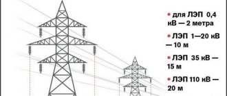
To prevent the development of fatigue damage to PA type hollow aluminum conductors near hardware terminals at a number of 500 kV
MES, Trubnaya) since 2001, protective spiral protectors of the PZS-Dpr-41 and PZS-Dpr-42 types have been used for PA-640 and PA-500 wires.
PZS-Dpr-41 are made of galvanized steel wire, PZS-Dpr-42 are made of aluminum alloy ABE to prevent heating of the protector by eddy currents near powerful sources of electromagnetic fields (Fig. 5.17). Rice. 5.17. General view of PZS-59.0-42 on a PA-640 wire Protection of the AC 300/204 overhead line 330 kV "Konakovskaya GRES - Kalinin" in a multi-roller suspension at the crossing of the river.
Volga (MES CENTER). P
after 22 years of operation of the AS 300/204 wires of the 330 kV overhead line "Konakovskaya GRES - Kalinin" at the crossing of the river. Volga on a multi-roller suspension under the protective aluminum couplings and at their joints, numerous breaks in the wires were found in all layers (Fig. 5.18.).
Rice. 5.18. A fragment of a wire with signs of wear under aluminum couplings
Under individual couplings of 54 aluminum wires, only 8 retained their integrity. It was decided to replace the damaged wire with the installation of a protective protector of the PZS-29.2-21 brand instead of aluminum protective couplings of the MZ type. In February 2004, the Konakovo crossing was successfully repaired. In Figures 5.19-5.20. shows a fragment of the installation and a PZS-29.2-21 protective protector mounted on an AC 300/204 wire in a P6R multi-roller suspension.
1- wire AC 300/204; 2-bottom layer of tread; 3-top layer of tread
Rice. 5.19. Fragment of installation and structural
features of the protector PZS–29.2–21
Rice. 5.20. Protective protector PZS–29.2–21 on
wire AC 300/204 in multi-roller suspension P6R
To date, such protectors have been equipped with the crossings of the 220 kV overhead line "Central - Pinyagino" (MOSENERGO) on the AC-400/93 wire (2003) and the 35 kV overhead line on the AC-185/128 wire across the Eastern Bosphorus Strait near Vladivostok ( 2003), etc.
The use of spiral tension clamps on 500-750 kV overhead lines (MES CENTER).
In 2003, during the construction of a new 750 kV overhead line "Kalinin NPP - Cherepovetskaya", tension spiral clamps of the NS-24.0-02 brand were used to fasten the AS-300/39 wire. The clamps are made of aluminized steel wire, which has a higher durability and corrosion resistance. Figure 5.21 shows a fragment of the construction of a 500 kV overhead line using tension spiral clamps.
Rice. 7.22. Fragment of the construction of a 500 kV overhead line
Many years of experience (1992-2006) clearly show that the use of spiral clamps significantly simplifies and speeds up repair and restoration work compared to traditional technology.
As a result, the cost of repairs is significantly reduced. Developed technical solutions for the repair of wires and lightning protection cables using spiral reinforcement make it possible to restore their condition to standard, with almost any type of damage, in a very short time and without the use of special tools. This allows not only to increase the service life of the wire during operation, but also to avoid its premature replacement. Catalog:
files -> library -> 072011 library -> Service life standards for starter lead-acid batteries of vehicles and forklifts library -> Russian Society of Surgeons Interdisciplinary Scientific Surgical Society 072011 -> Repair of wires on a 500 kV overhead line baes-pipe
144.75 Kb.
Share with your friends: