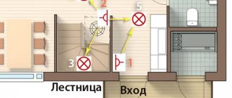
Connection diagram for a two-key pass-through switch used quite often in residential and public buildings. It is known that in spacious rooms or long corridors it is extremely inconvenient to use only one switch installed at the entrance itself.
For some time before turning on the device or after turning it off, you will have to do without light. There is only one way to avoid this inconvenience - to install devices of a special design at the entrance to the room, as well as at its exit (they are called pass-through switches or switches).
Design and principle of operation
With the help of such switches, it is possible to control the same light source from two or more points, turning it on in one place and turning it off in another (or vice versa). Thanks to this, while moving, the corridor will be constantly illuminated along the entire path.
The rear view of two-key pass-through switches from different manufacturers is shown in the figure below.
The connection diagram for a double pass-through switch can be implemented using a single-key device, so the question is quite logical: what is the second key for then?
To answer this you will need to understand the following explanations:
- A two-key pass-through switch also contains changeover contacts, but in this case the number of switching groups of lamps increases from one to two .
- The number of conductors connecting two spatially separated switching devices increases to 4.
- With this connection diagram for two-key pass-through switches, it becomes possible to switch two lighting bulbs at once (one to turn on and the other to turn off).
- To see the difference between two-key and single-key switches, a direct comparison will help us. To do this, you will need to remember the connection diagram for the pass-through switch, in which the connection is made on only two wires.
Important! When examining the two schemes together, one can immediately see the difference not only in the number of connectors, but also in the functionality of the devices used.
If in the case of a single key only one group was switched (the lamp was turned on and off), then in a chain with a two-key switch there are already two such groups. According to the diagram of two-key pass-through devices, in this situation it will be possible to turn on the first of 2 light bulbs while simultaneously turning off the second and vice versa.
Operating principle and differences between pass-through switches and conventional ones
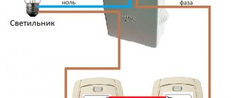
The operating principle of standard wall-mounted lighting switches is based on a break or connection of the supply phase.
Note! According to the rules of the PUE, it is necessary to break the phase in the switch, and not the zero.
This is important for the safe operation of lighting devices and the absence of voltage on them when turned off using the switch. A conventional switch has two contacts: one for connecting the power phase and the other for connecting a lighting device. In this case, the switch has two positions: “on” and “off”.
The pass-through switch has the same size and appearance (to suit any interior and color schemes), but is structurally somewhat different from the usual one: it does not have an “off” position and has 3 contacts for connecting outgoing conductors. Such a device is mounted in pairs with another switch of the same type. In a pass-through switch, the circuit does not break, but the phase is transferred from one contact to another.
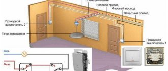
Lighting control scheme from two places
By connecting double pass-through switches, it is possible to control two light bulbs alternately from two places. This circuit contains a pair of two-key switches, which allows you to turn on one of the lamps at the entrance, while simultaneously turning off the other. When exiting a long corridor, for example, a second device allows the reverse operation. Thus, lighting control is carried out alternately from 2 places.
Important! In this case, the direction of movement along the corridor is not of fundamental importance.
It is possible to implement such a control algorithm only if there is a double pass-through switch. Systems organized in this way significantly simplify lighting control in the conditions described above.
Installation procedure
Before connecting pass-through two-key switches and illuminators, places for their installation are first selected (the first ones should be located at the very exit-entrance to the room). After this, they move on to the main work, carried out in the following sequence:
- First of all, at selected points, installation niches are drilled into the walls with a special crown, the diameter of which is selected to be 72 or 80 mm (depending on the device housing).
- Then special plastic boxes are fixed into them (they are called “socket boxes”).
- When laying the wiring externally, the housings of the switching products are mounted on the wall using self-tapping screws.
- Upon completion of the installation of two-key pass-through switches, proceed to the installation of two groups of illuminators, in each of which the lamps are switched on in parallel (this will eliminate the possibility of a complete blackout of the circuit if one of them burns out).
- Then, two phase wires and one neutral wire are laid from the installed chandeliers or lampshades to the distribution box.
Since the requirements of the PUE require grounding of any connecting wiring with loads, a cable with three cores is laid from the lamps.
Please note: It is recommended to choose the location for installing the distribution box (RC) in the middle of the room, which allows you to save on the length of the wires.
Since the design of the two-key pass-through switch has 6 contact terminals, two 3-core cables will need to be laid from it to the switch. When disconnecting system elements, the wires to the RC must be connected according to the diagram below.
We suggest watching a video on how to connect two-key pass-through switches without a junction box.
Attention! In this installation option, the socket boxes must be deep.
How to install in a junction box
In order for a double pass-through switch or lighting devices to perform their function for many years, the switching process must be approached thoroughly.
Often, due to negligence or lack of extensive experience in performing electrical work, twists can be found in junction boxes. However, this is a serious violation, since over time, contact may be lost in these twists, as a result of which the wires will begin to heat up, burn out, and a fire will occur. It is also strictly forbidden to connect copper and aluminum wires without any interlayer.
For reliable connection of cables and wires in junction boxes, 3 methods are recommended:
- Soldering contacts.
- Welding of conductors using special transformers.
- Connecting conductors using special clamps (WAGO).
Lighting control scheme from three places
In order to control lighting from three places at once, the previously used scheme with two two-key devices will need to be supplemented with one more (it is called cross). This switch can be placed anywhere in the room between two already installed products.
Structurally, a cross double pass-through switch consists of two two-key devices combined in one housing. In this product, instead of two, one common key is installed on a conventional changeover mechanism, due to which the switching of both lines is carried out synchronously.
The 3-point connection diagram is organized in such a way that the neutral wire is supplied to both lighting groups at once, and the phase wire is supplied to each of the inputs of the first two-key switch. Regardless of the position of the keys, current will flow only through 2 of the 4 input terminals. From the first pass-through switch, the current flows through the jumpers to the input of the cross switch, and then to the second pass-through switch.
This position of the switch keys determines the path of current through the lighting fixtures. If this group is in working condition (the lights are on), just press the key of any of the switches to remove power from it. The same thing happens when they are turned on: when you change the position of any key, the power circuit is immediately restored.
Operating principle of a pass-through switch
In appearance, pass-through switches are identical to standard ones, but due to their design, their operating principle is significantly different.
So, when you press the key of a regular switch, the circuit simply closes or opens, but if you press the key of a pass-through switch, it opens one group of contacts and closes another.
Important! Unlike standard two-key (single-key) devices, pass-through switches can only work in pairs, since one and the second control the phase supply to the lighting device and if one of them is not in the circuit, then the phase wire will not flow to the lighting source, as a result the light will not light up.
Let us next consider what the connection diagram for a pass-through switch from 2 places should be, since this is considered the most common option for implementing lighting systems in houses, apartments or offices.
Four-place lighting control circuit
To organize control of lighting devices from 4 points at once (in two directions) in the room, you will need to install a couple of cross switching products. If there are several lighting groups, preference is given to two-key cross-type switches. When they are connected in series, not only the electrical wiring becomes more complicated, but also the installation of the products themselves according to the algorithm already discussed above.
In this case, jumpers will need to be installed twice (in both pass-through switches, the diagram of which is shown above). When disconnecting such systems, it is recommended to strictly follow the sketch drawn in advance with the designations of the contacts and jumper conductors indicated on it.
conclusions
Pass-through single-key and two-key switches are modern switches that allow you to organize control of one or more lighting sources from different places in one or adjacent rooms.
As can be seen from the above information and photos, we can say that despite the design (single-key or pass-through two-key switch, the connection diagram for 2 sources) is very easy to install and allows you to effectively control the lighting in a huge cottage, a large retail space or in industrial buildings.
To connect these devices it will be enough:
- two pass-through switches with 2 keys or two single-key switches;
- distribution box;
- flexible cable with three cores.
Connection diagram for a three-key pass-through switch
When familiarizing yourself with the diagram of a pass-through three-key switch, you need to pay attention to the following points:
- The devices in question have 6 output contacts, which allows you to control three groups of illuminators while being at one access point.
- Before connecting a pass-through switch with three keys, you will first need to mount its loads and disconnect them according to the lighting plan.
- The three-key pass-through switch, the diagram of which is shown in the figure on the right, is not intended for pass-through purposes.
- The main purpose of these devices is to save on wiring costs by controlling multiple illuminators from a fixed point.
In conclusion, we note that the technique of installing a two-key pass-through switch from two places and all its subsequent modifications (from three and four points) resembles the same operations for single-key devices. Its slight complication is justified by a significant expansion of the system’s functionality, supplemented by another illuminator, switched “out of phase” with the first.
Basic recommendations for installing two-key pass-through switches
When installing both standard and two-key pass-through switches, it is recommended:
- The placement height from the floor level should be 90 cm.
- The distance from the door or window opening to the pass-through switch must be at least 15 cm.
- Distribution boxes with switching must be located in a visible place and at the same time they must be placed at a distance of 15–30 cm from the ceiling level.
- For installation of pass-through switches, it is recommended to use a 3-core flexible cable with a cross-section of 1.5 mm² (VVGng, PVSng, ShVVP, and so on).
- Cable and wire products must be laid in corrugation, in grooves or cable channels.
- All metal surfaces of lamps must be grounded.
Connecting pass-through and cross switches
Introduction
In one of the previous articles, we already examined in detail the connection diagrams for simple one- and two-key switches (for more details, see the article: Connecting a switch), however, such switches have one serious drawback - lighting control, i.e. turning it on and off can only be done from one place. Let's imagine a situation that everyone has encountered, for example: You come home, turn on the light in the hallway, take off your outerwear and go into the room, but wait, the light in the hallway needs to be turned off, and having done this you will have to leave the hallway in the dark, the same goes for long corridors or staircases. In such situations, it becomes necessary to control lighting from two places; it is for solving such problems that the so-called pass-through switches are designed.
In this article we will look at various options for connecting pass-through switches to control lighting from 2, 3 or more places.
NOTE: Before connecting the pass-through switch, you must check the diagram given in its passport and/or the diagram printed on the back of the switch itself (if available).
Pulse relay circuit
Switching on lighting from two or more places can be organized using a so-called pulse relay. This option is even easier to implement.
Operating principle of a pulse relay
Before we figure out the wiring diagram for such a relay, let's figure out how it actually works.
Understanding the work process will greatly facilitate the connection and eliminate the possibility of errors:
- A conventional relay has a coil and an open magnetic circuit. When voltage is applied to the coil, the magnetic circuit tightens and becomes a single whole. Contacts are rigidly attached to the magnetic core, which, when the magnetic core is pulled up, are also pulled up and closed with the fixed contacts. If a lamp were connected to these contacts, it would light up.
Simplified diagram of the operation of a conventional relay
- But in a conventional relay, as soon as the voltage on the coil disappears, the magnetic circuit, and accordingly the contacts, return to their original position - they disappear. Accordingly, our lamp will go out.
Impulse relay
- In a pulse relay, everything is a little different. When voltage is applied to the coil, the magnetic circuit tightens and closes the contacts. In this case, the contacts are fixed in this position. Therefore, even when the voltage on the coil disappears, they remain in this position.
- To change the position of the contacts, it is necessary to reapply voltage to the coil. Then the contacts will open and lock in the open position.
Note! We describe the operating principle of an electromagnetic pulse relay. There are also electronic ones that do not have coils and magnetic circuits. Their operating principle is different in many ways, but the end result is the same.
- To supply voltage to the coil, the instructions advise using regular buttons - such as on a doorbell. Even a short press is usually enough to trigger the relay. Typically this time is an order of magnitude less than one second.
Button for controlling relay RIO-1
Button for controlling RIO-1 back side
But only the relay is powered by the buttons. A power relay contact is used to supply voltage to the lamps. Therefore, it is necessary to connect its own phase wire, which, when the contacts are closed, will supply voltage to the lamps.
Pulse relay connection diagram
For a pulse relay, the lighting control circuit from two places or more is practically no different. Therefore, if you need to control lighting from three, five or ten places, simply add the number of buttons to the circuit.
So:
- First of all, let's figure out how to connect the relay itself. Usually it has as many as six contacts. Their names vary from manufacturer to manufacturer. Therefore, we will tell the story using the example of one of the most common relays - RIO-1.
- First let's assemble its power part. To do this, from the group phase wire in the distribution box, we mount the wire to contact “11”. When the relay is triggered, contact “11” will close with contact “14”. Therefore, from the latter we install a wire to our lamps.
Connection diagram for pulse relay RIO-1
- To connect the lamps, we will also need to connect the neutral and protective wires. We take them in the distribution box, and bypassing any switching devices, we connect them to the corresponding contacts of the lamp. The connection of the power section is completed.
- Now we connect the control of the RIO-1 relay. In our case, we need two buttons for this. From the group phase wire in the distribution box, we mount the wire to contact number one of the first button. From it - to contact number 1 of the second button.
- From contact number two of the second button, mount the wire to contact number two of the first button. From this contact we lay a wire to the relay. Here we connect it to the “Y” contact as in the video.
Pulse relay circuit
But to create a circuit on the coil, we still need to connect it to the neutral wire. Therefore, from the group neutral wire in the distribution box, we mount a wire to contact “N” of the RIO-1 relay. This completes the connection, and after applying voltage, the circuit is ready for operation. Agree, there is nothing complicated about this.