Many of us have heard terms like pass-through switch and crossover switch. What kind of switches are these and how do they differ from the usual ones found in every home? In this article we will solve this issue, and at the same time find out where these switches are used.
A regular switch can only close or open an electrical circuit. But this is not enough to arrange lighting control from two or more different points. For these purposes, pass-through switches are used, which are also called switches. With their help, they not only break the electrical circuit, but also switch current consumers from one line to another.
What is a pass-through switch and how does it work?
It would be more correct to call this device a switch - it is a switch for users rather out of habit, since it is used to turn lighting on and off. If you call it correctly, then it is much easier to understand how it differs from standard switches - this name most fully reflects the essence of its effect on a working electrical circuit.
Additional names are changeover, duplicate or cross switch.
Like a standard switch, a walk-through switch has only two positions, but the fundamental difference is that in a conventional device it is strictly defined, for example, up is on, and down is off, but with a walk-through, these sides are constantly changing.
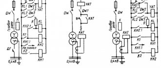
The operating principle of the pass-through switch becomes clearest when comparing the electrical circuits between it and the standard device, which is shown in the figure:
If a regular one in an open state simply breaks the circuit, then in the case of a pass-through one it all depends on the position of two switches at once:
From the diagram it is clear that each of the switches must have three terminals - one for the phase that comes from the power source and two for the “control” wires. When either of the two switches changes position, the circuit either closes or opens, depending on what state it was in before.
Additionally, we can formulate one more difference between a switch and a switch - the latter can always be connected as a simple switch, but doing the opposite will not work. When repairing such a circuit, it must be taken into account that one of the wires between the switches is always live.
Installation diagram of several switches
We have discussed the method of installing switches in the presence of one or two or three groups of lighting fixtures. After all, only two switches were required, which were located along a common line.
Now we need to consider a situation where there are several switches at different points. The bottom line is that they all need to control the same light fixture.
If it is necessary to organize control of a lighting device from three or more places, it will not be possible to use another switch other than a cross switch. Here one chain is incoming.
Here one chain is incoming
The switches, which are located on both sides, are connected according to the standard scheme. Only between them is another one, which has four clamps for connecting wires. After pressing one of the keys in this system, the connected contacts open and a cross-circuit occurs in a new circuit.
Of course, in addition to standard single-key devices, multi-key crossover switches are often used. This connection is required if there are several groups of lamps. However, here too you will have to make more connections using clamps. In addition, an inexperienced craftsman can easily confuse the wires, so care should be taken.
If it is necessary to install an additional point for “closing-opening”, then another crossover switch is installed with wiring connected to the already installed device.
Crossover switch
Craftsmen recommend making electrical wiring connections by passing conductors into the junction box. However, some people may find it easier to bypass the box using a wire and two strands.
As has been observed in practice, this is a rational connection method that does not violate safety regulations. In addition, such a connection allows you to reduce the cost of purchasing additional wires.
Common connection errors
What is a pass-through switch used for?
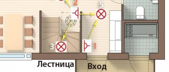
The main feature of a pass-through switch is the ability to turn on the light in one place, go to another and turn off the light there. So conveniently and comfortably, any number of people can move in any direction and sequence. That is why the device is called a pass-through device.
In practice, this is very convenient to go through, for example:
- from the garage to the house down the street;
- follow the long corridor;
- climb the stairs from the first floor to the second;
- turn on the light at the bedroom door, walk to the bed and turn it off.
In all four cases, a pair of pass-through switches will help us out. The convenience of using such devices in large apartments and houses is especially noticeable. To control lighting in more complex combinations with several lamps and control points, pass-through switches with different numbers of keys and internal circuits are used.
Principle of operation
Walk-through switches are no different in appearance from conventional key switches - their design and principle of operation have their own specifics. The main differences between these switching devices are the number and order of connection of the switching contacts.
When operating 2-pass switches, the order of breaking and closing the chain supplying phase voltage to the lighting device is more complex and branched. During the switching process, two such switches, the diagram of which is discussed below, close one of the connecting lines while simultaneously opening the other.
Due to this, it is possible to implement the principle of separate control of the same lighting device from two places located at a considerable distance from one another. The most typical example of such an organization is the location of switches at opposite ends of a long corridor. This feature ultimately determines the specifics of installation of walk-through switches within the boundaries of a particular inhabited room.
Selection, design and differences of pass-through switches
Before assembling such a control scheme, here is what you should pay special attention to:
- To connect a pass-through light switch, a three-core cable is required - VVGng-Ls 3*1.5 or NYM 3*1.5mm²
- Do not try to assemble a similar circuit using ordinary switches.
The main difference between regular and pass-through ones is the number of contacts. Simple single-key ones have two terminals for connecting wires (input and output), while pass-through ones have three!
In simple terms, the lighting circuit can be either closed or open, there is no third option.
It is more correct to call a pass-through not a switch, but a switch.
Since it switches the circuit from one working contact to another.
In appearance, from the front they can be absolutely identical. Only the pass key can have an icon of vertical triangles. However, do not confuse them with reversible or crossover ones (more about them below). These triangles point in a horizontal direction.
But from the reverse side you can immediately see the difference:
- the pass-through has 1 terminal on top and 2 on the bottom
- a regular one has 1 on top and 1 on the bottom
Due to this parameter, many people confuse them with two-key ones. However, two-key ones are also not suitable here, although they also have three terminals. The significant difference is in the operation of the contacts. When one contact is closed, pass-through switches automatically close the other, but two-key switches do not have such a function. Moreover, there is no intermediate position when both circuits are open at the gateway.
Design and features of using switches
Electrical network switches are switching devices. It allows you to open and close lines, but it simply redirects the current. When one circuit connected to the device is active (it has power), the second is turned off. And, accordingly, when the second is active, the first is disabled.
In domestic conditions, as a rule, models oriented towards two lines are used. But from a technical point of view, nothing prevents us from making a device capable of switching a larger number of networks. This, of course, will lead to increased structural complexity.
Structurally, the switch consists of three contacts and a metal plate. The phase is supplied to the first, and the outputs of the switched lines are supplied to the second. When you press the button, the metal conductor plate closes one controlled contact and opens the second, and the next time you press it, it opens the first and closes the second.
Switches are used both to switch between two circuits and to create a lighting system that is controlled from two points. For example, if you want to turn on a lamp at one end of the corridor and turn it off at the other. If you plan to create a lighting system controlled from three points, you will need a crossover (pass-through) switch. Its design complexity is slightly higher (four contacts, one plate), but the operating principle is approximately the same.
So, the switch switches electricity between two circuits, one of which is active in each mode of operation of the device. It does not open the circuit, but redirects the current simultaneously with the circuit breaking.
Similarly, almost all presented models of such units are intended for use in household networks with electrical parameters of 220 V and 6-10 A. They are not equipped with arc extinguishing units, do not support automatic opening in the event of a short circuit, and if “sparks” begin to be observed, it is required make immediate replacement.
Advantages of installing a pass-through switch
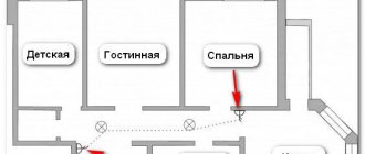
Pass-through switches allow you to control room lighting from two or more places, which is an undeniable convenience. This is especially valuable for multi-story houses with flights of stairs. Here you can install the first switch on the first floor and the next on the second, which will turn on the light downstairs and turn off the upstairs.
The use of walk-through switches to control the lighting of staircases is especially important. A good solution is to install one switch at the entrance to the bedroom, and a second near the head of the bed, which will allow you to enter, turn on the light, get ready for bed, lie down and turn off the light. It is also advisable to install switches at the entrance to a house or apartment and at the end of the corridor.
Helpful advice! Using special motion sensors or a timer built into the switch, you can automatically turn off the lighting when leaving a certain place.
Walk-through switches have significant advantages compared to conventional devices:
- high reliability and safety of operation;
- instant shutdown of the power supply to the premises, if necessary, from any point;
- optimal energy consumption;
- low cost;
- simple installation that does not require the involvement of specialists;
- no complicated settings.
It will be interesting➡ Twilight switches
The presence of walk-through switches allows you to turn on the lamps below with one switch, and when going up the stairs, turn them off with another
Reading Electrical Diagrams
Placement of sockets in a residential apartment
It is necessary to understand the compiled electrical circuit: how it works, possible malfunctions and other nuances. This process is called “reading circuit diagrams.” To do this, you need to know the conventional graphic symbols of all the parts depicted on it, as well as their connections.
Conductor designations
Wires connecting elements of electrical circuits are depicted as lines. They differ in explanatory inscriptions, numbers and, in some cases, thickness. In a single-line diagram, a thick line depicts a group of wires: phase and neutral or “plus” and “minus”.
In drawings with a large number of details, the conductors are not shown as a solid line, but at the beginning and end of the connection, with each wire marked and the connection location indicated. The wires going from one sheet to another are also shown.
Hardware graphic symbols
In addition to wires, electrical circuits contain other equipment. All its types have their own conventional graphic images. They symbolically display the functions or design of devices. This is a schematic representation of circuit breakers, limit switches and lamps, made from simple geometric elements. Their combination carries all the information about the electrical appliance.
All symbols and their elements are indicated in special tables defined by GOST 21.614-88 “Conventional graphic images of electrical equipment and wiring on plans.” It is mandatory not only in production, but also when designing household electrical wiring.
Connecting a pass-through switch
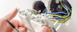
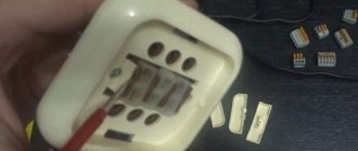
First of all, you need to correctly connect the switch itself in the socket box. Remove the key and the overhead frames.
When disassembled, you can easily see the three contact terminals.
The most important thing is to find the common one. On high-quality products, a diagram should be drawn on the reverse side. If you understand them, you can easily navigate through it.
If you have a budget model, or any electrical circuits are a bit of a mystery to you, then an ordinary Chinese tester in circuit continuity mode, or an indicator screwdriver with a battery, will come to the rescue.
Using the tester's probes, alternately touch all the contacts and look for the one on which the tester will “squeak” or show “0” at any position of the ON or OFF key. It's even easier to do this with an indicator screwdriver.
After you have found the common terminal, you need to connect the phase from the power cable to it. Connect the remaining two wires to the remaining terminals.
Moreover, which one goes where does not make a significant difference. The switch is assembled and secured in the socket box.
Do the same operation with the second switch:
- look for the common terminal
- connect the phase conductor to it, which will go to the light bulb
- connect two other wires to the remaining ones
Furniture and interior items
0 votes
+
Vote for!
—
Vote against!
Changing a switch is a problem that we all face sooner or later. In this article we will look at the most commonly used single-key switch, as well as its connection diagram and nuances that must be observed during operation.
Content:
- What to look for when choosing a switch
- Single-key pass-through switch.
- What is the difference between a regular switch and a pass-through switch?
- Video installation
- Installation of a single-key switch
- Installation of a distribution box for one lighting group video
- Installation of a hidden switch
- Installation of surface-mounted switch
What to look for when choosing a switch
It is best to buy switches in specialized stores, where the assortment allows you to choose exactly the option that suits you best in terms of functionality and design. Also in the store you can find high-quality branded switches, for example, Legrand single-key switches.
When purchasing a switch for general-purpose electrical wiring with a voltage of 250 V and a load of 10 A, make sure that it complies with GOST R 51324.1-99. Also, the product must bear the quality mark of the country of origin. If we are talking about a switch made in the Russian Federation, then this should be the Rostest badge.
Pay attention to what voltage and current the switch is rated for. For example, switches with cermet contacts containing silver will operate reliably at currents up to 4 A. Be sure to look at the number of switching circuits and the number of poles (single-pole, double-pole, or three-pole). Well, of course, it is worth paying attention to the design of the mechanism (cord (ceiling) switch, push-button, key, flip or rotary) and the design of the housing (for embedding in electrical appliances or for installation on an electrical wire, for open or hidden electrical wiring).
For example, a single-key switch for hidden electrical wiring is distinguished by a design that provides for the connection of electrical wires after the switch itself is fixed in a socket on the wall. This way you will be able to keep the wires from unnecessary bends.
The single-key open switch is mounted on wooden sockets, to which they are attached with two screws.
If you plan to install the switch in a place where there is a risk of water getting inside, pay attention to single-key splash-proof switches.
When you choose the model that best suits your specifications, do not forget to check the softness of the keys. To do this, you just need to “turn on and off” the key a few times, and everything should work quite smoothly - nothing should creak or cling. Finally, pay attention to the build quality.
Single-key pass-through switch
Installing a pass-through switch makes sense in places where conventional control of lighting on and off is inconvenient and impractical. In particular, we are talking about long corridors, flights of stairs, etc. As a rule, in such places special single-key switches are installed, equipped with three contacts, the special connection diagram of which is implemented as switches. During operation of such a device, the electrical circuit switches between two output contacts rather than breaking.
When choosing a pass-through switch, pay attention to the modification of the device, which may differ depending on what kind of wiring the device is designed for - hidden or open. So, when purchasing a switch, take into account all the characteristics of the device, since the contacts are designed for different currents and, accordingly, can withstand different loads.
What is the difference between a regular switch and a pass-through switch?
The main difference between a walk-through switch and a conventional switch is the presence of a special mechanism that ensures switching between the three contacts that are provided in such switches. The operation of a pass-through switch is not based on the usual interruption of the electrical circuit, but on the ability to switch between contacts.
Connection diagram for pass-through switch:
Connection diagram for pass-through switch:
Hence the main advantage of pass-through switches, which is the ability to turn a lighting device on and off from two or more points.
As already written above, it makes sense to install pass-through switches in long corridors and on flights of stairs, for example on the first and second floors. That is, on the first floor we can turn on the staircase lighting, and when we go up to the second floor, turn it off.
Also, pass-through switches can be installed in the bedroom - one at the front door and one at the bed - or in garden plots, when there is a need to illuminate paths at night.
Instructions for installing a pass-through single-key switch:
Installation of a single-key switch
If you need to replace an old, faulty switch, then this type of work will take you very little time and difficulties as such will not arise during their implementation. However, if we are talking about installing a new circuit in a house or apartment, then in this case the work ahead will be more complex. Below we will tell you how to install hidden and overhead switches yourself.
Installation of a distribution box for one lighting group
Be sure to make sure that the power is turned off before installing the switch.
If we are talking about creating a new circuit, and, accordingly, the need to carry out new wiring, you must immediately decide for yourself what it will be - open or closed. Of course, with open wiring that is laid along the surface of the building (either openly or in a special box) there will be fewer problems. For such wiring, an overhead or, as they are also called, an open installation switch is suitable.
If you do not want the wiring to be hidden, then you cannot do without more extensive work, in particular, wall slitting.
So, in contrast to what kind of wiring they decided to install the switch, it could be either an external installation or a hidden installation. In the latter case, the switch is mounted in a box built into the wall. In the first, it is simply placed on the surface of the wall.
If you are laying a new circuit and planning to install a distribution box for one group of lighting with a single-key switch and a luminaire for one group of lamps, then six wires must be routed into it. Two wires for the lamp, two for the switch and two for power supply. The diagram of such a circuit will look like this:
When all the wires are inserted into the junction box, we determine them using an ohmmeter, the wires supplying a phase voltage indicator and a test lamp. Having identified the wires, the neutral working conductor (N) must be connected to the wire of the lamp connected to the side contact of the electrical device, and the phase conductor (L) must be connected to the wire going to the switch. We connect the remaining two wires to each other.
Installation of a hidden switch
If you just want to change the switch, then all the work described above is, of course, not necessary. Or, when you have determined exactly where the switch will be located and ran the wires to this location, you can begin installing the switch itself.
Installation of a single-key concealed switch requires the installation of a metal or plastic mounting box; they can also be for hollow or solid walls.
The standard size of such a box is 4 cm deep and 7 cm diameter. As for the material, it is better to give preference to heat-resistant plastic, as it is much safer than metal.
Before installation, you should unscrew the screws from the installation box and break off the plug for the holes for the wires entering it. To keep the box more securely in the wall niche, it is recommended to use alabaster. Boxes for hollow walls, for example, made of plasterboard, are fastened with brackets.
Connection diagrams for a single-key switch:
There are four ways to connect wires to the switch, and not all of them are considered safe:
- The wire is clamped with the cross-section of the screw. This type of connection is the most dangerous, since in this case the wire can simply be cut during the tightening process.
- The quick-clamping method involves installing the wire into the hole while the key is pressed. Then, when the key is released, it clamps down. This method is bad in that during operation of the switch the spring gradually loses its physical properties, and therefore the clamping force weakens and the contact may begin to heat up.
- The wire is pressed against the contact plate by the head of the screw.
- The last method is the most reliable and consists of pressing the wire with a plate, which moves with the help of a screw and clamps the wire.
So, having figured out how to connect the wire, you can proceed directly to installing the switch. To do this, carefully use a screwdriver to remove the key and the latch that holds the top cover. After removing the cover, the switch can be disassembled easily and simply.
Clamping the wires in the sockets, the switch is secured in the box using screws or special levers.
Installation of surface-mounted switch
The process of installing a surface-mounted switch is similar to a hidden one, with the only difference being that there is no need to rout the walls and install a mounting box. The only drawback of a single-key external switch is its size.
In general, the entire process of installing such a switch comes down to marking future mounting holes, drilling them, installing dowels and, in fact, connecting the wires and attaching the switch to the wall.
That's the whole simple process of installing a single-key switch. As you can see, if we are simply replacing an old switch with a new one, then the installation process is so simple that you can handle it yourself without calling an electrician. If we are talking about creating a new circuit and installing a new junction box, then, of course, for safety reasons it is better to seek help from a specialist.
Rules for connecting a pass-through device
I provide both the installation and electrical connection diagrams for the devices under discussion. As you can see, if the keys of both devices are either in the up or down position, the lighting does not work. In the other two cases, electricity is supplied to the lamp.
It is immediately obvious that a connection of two wires is required between the two devices. In practice, this circumstance significantly complicates the installation of electrical wiring. If an existing lighting circuit is being modified, it is possible that an additional two-core cable will have to be laid between the two devices.
In a classic wiring diagram using distribution boxes, a three-core cable should be connected to each device, and four connections must be made in the box, provided that the neutral wire is already connected to the lamp. All work is carried out when the power is turned off. If there is a need to groove cable channels, you must first check the presence of wiring at the work sites using a special tester.
How should I connect a double crossover switch?
Let's take a closer look at how legrand is installed. Before you start installing the legrand double switch
, it is necessary to create a plan for future work. Thanks to this, it will be possible to calculate the amount of cable. After creating the plan, it is necessary to make channels in the walls for the future cable.
Let's look at how a paired and pass-through switch is connected:
- First, a standard scheme using pass-through models is used. It is necessary to stretch the neutral wire from the switchboard to the junction box. From the junction box the cable is connected to the lighting fixture;
- Then you need to stretch the phase wire from the shield. From the distribution box it is supplied not to the lighting fixture, but to the switch contacts;
- In the distribution box, all contacts are connected in series. The wire with the phase is connected to the crossover switch, and it is located between several pass-through switches.
- Then, from the last pass-through switch, the common contact is connected to the lighting device. After the cable pulling is completed, the junction box is installed. It can be installed on a wall or inside a wall.
In the presented circuit, a pulse is simultaneously transferred to a pair of contact groups. Although this connection is very simple and convenient, it is rarely used by electricians, as they believe that two pass-through models are more reliable.
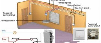
Connection diagram for the pass-through switch wires in the distribution box
Circuit without grounding conductor
Now the most important thing is to correctly assemble the circuit in the junction box. Four 3-core cables should go into it:
- power cable from lighting circuit breaker
- cable to switch No. 1
- cable to switch No. 2
- cable for lamp or chandelier
When connecting wires, it is most convenient to orient them by color. If you use a three-core VVG cable, then it has two most common color markings:
- white (gray) – phase
- blue – zero
- yellow green – earth
or second option:
- White gray)
- brown
- black
To choose a more correct phasing in the second case, follow the tips from the article “Color marking of wires. GOSTs and rules.”
1Assembly begins with neutral conductors.
Connect the neutral conductor from the cable of the input machine and the neutral going to the lamp at one point using the terminals of the car.
2Next you need to connect all the grounding conductors if you have a grounding conductor.
Similar to the neutral wires, you combine the “ground” from the input cable with the “ground” of the outgoing cable for lighting.
This wire is connected to the lamp body.
3 All that remains is to connect the phase conductors correctly and without errors.
The phase from the input cable must be connected to the phase of the outgoing wire to the common terminal of the pass-through switch No. 1.
And connect the common wire from pass-through switch No. 2 with a separate wago clamp to the phase conductor of the lighting cable.
Having completed all these connections, all that remains is to connect the secondary (outgoing) conductors from switch No. 1 and No. 2 to each other. And it doesn’t matter at all how you connect them.
You can even mix up the colors. But it’s better to stick to the colors so as not to get confused in the future.
At this point, you can consider the circuit fully assembled, apply voltage and check the lighting.
The basic connection rules in this diagram that you need to remember:
- the phase from the machine must go to the common conductor of the first switch
- and the same phase should go from the common conductor of the second switch to the light bulb
- the remaining two auxiliary conductors are connected to each other in the junction box
- zero and ground are supplied directly to the light bulbs without switches
DIY checkpoint
To independently change the places where the lights are turned on, you need basic knowledge in electrical engineering: what an electrical circuit is, the ability to read and draw an electrical circuit, the ability to use a multimeter, continuity tester or tester, to know the difference between phase and zero and voltage and current.
To save money, you can make the necessary light switch yourself. To determine what type of switch is needed, you need to draw a plan diagram of the remodel. The installation for the pass-through switch is the same as for conventional ones. Only the number of wires and twists increases. Everything is connected according to the project.
Let's look at how to make a pass-through switch with your own hands. Most often they assemble a single-key one. There are several options here, for example, assembling a pass-through switch from a regular one. Another option is to assemble it from 2 simple switches from the manufacturer. The best option is Lezard switches.
It’s even cheaper to use a changeover toggle switch, 5-10 amperes. You can use a toggle switch with a 220 volt relay and a switching current of up to 5 A. Another option is to use roller switches, rotary or push-button. But this design is more cumbersome.
Making a pass-through reliable switch yourself is problematic. You can use biscuit switches with the necessary set, a relay with 220V switching contacts and a toggle switch to turn on the relay.
Three-key switches are rarely used, and they are not commercially available, but they can be replaced using electronics. This will cost more, it’s cheaper to order ready-made.
Along with the electrical diagram, it is necessary to draw an electrical wiring diagram, showing where and how to connect the triple switch and all other switches and loads. It will be like a cheat sheet when you connect the wiring so as not to mix up the wires.
All intermediate connections are made in the distribution box using the twisting method or special clamps. Place the connected wires in plastic channels. If possible, use a distribution board.
Must remember! The total load power of an average apartment does not exceed 16-25 amperes.
It is advisable to divide the electrical wiring into power groups evenly. If you are not confident in handling the installation work, you must contact professional workers. When installing touch switches, the touch panel must be removed and installed after completion of work.
The use of modern devices brings everyone closer to living in a smart home. Increasingly, the capabilities of a lamp with a motion sensor and other sensors are being used, which allows saving energy on switching equipment and wires.
Connection errors
Many people make a mistake at the stage of searching and connecting the common terminal in the pass-through switch. Without checking the circuit, they naively believe that the common terminal is the one with only one contact.
They assemble a circuit in this way, and then for some reason the switches do not work correctly (they depend on each other).
Remember that on different switches the common contact can be anywhere!
And it is best to call it, what is called “live”, with a tester or an indicator screwdriver.
Most often, this problem is encountered when installing or replacing pass-through switches from different companies. If everything worked before, but after replacing one circuit the circuit stopped working, it means the wires were mixed up.
It will be interesting➡ Operating principle of a constant voltage generator
But there may also be an option that the new switch is not pass-through at all. Also remember that the lighting inside the product cannot in any way affect the switching principle itself.
Another common mistake is incorrectly connecting crossovers. When both wires are placed from pass-through No. 1 to the upper contacts, and from No. 2 to the lower ones. Meanwhile, the cross switch has a completely different circuit and switching mechanism. And you need to connect the wires crosswise.
Scheme for connecting a lamp from two places
Since this is a simple circuit, you will need to purchase two classic switches and wires for switching. Of course, here you will still need to adhere to safety precautions when carrying out electrical installation work. After all, this is not only a guarantee of proper operation of the equipment, but also an opportunity to avoid electric shock.
A simple installation diagram for a pass-through switch, which is used for installation in long hallways and on stairs
In order to understand how the electrical wiring connection occurs, you need to familiarize yourself with the detailed installation.
Differences between pass-through and traditional switch
The difference between a pass-through and a regular switch (rear view) The switches are no different in appearance. The internal structure of a conventional one is equipped with one input and output. Can have up to three keys, allowing you to control multiple lighting sources.
Most often they are installed near the entrance to the room. The connection is made using two terminals. A classic checkpoint has two exits and one entrance. In this case, the electric current is not interrupted, but is redirected to any other output. There is a diagram underneath the product body.
The single-key pass-through is equipped with three-wire switching and three terminals with copper contacts. This is a switch that redirects the current to other areas. By design, installation method and type of control, switches can be:
- keyboards;
- push-button;
- sliders;
- traction;
- toggle switches.
They are also classified depending on voltage and current, degree of protection, and climatic conditions in which they are installed. It is important not to confuse an electrical appliance with a changeover or crossover device. On the pass key there is a vertical triangle, in the rest it is located in the horizontal direction.
Connection diagram for two lighting fixtures
Of course, the first option is popular and easy to implement, so it is used everywhere. However, there are two or three lamps or several light bulbs in a room, which are divided into groups, so the standard scheme is no longer suitable here.
If you need to perform installation with two groups of lighting fixtures, you will need to purchase a switch with two keys, which has six clamps.
Switch with two keys, where there are six clamps
Otherwise, in terms of installation method and equipment, this scheme is not much different from the previous one. However, more electrical wiring will have to be installed here. Therefore, in order to reduce the cost of purchasing wires, it is recommended to connect the power conductor to the first switch in the chain with a jumper. Otherwise, you will have to lay separate conductors from the junction box.
Important. If there are three groups of lighting fixtures, you will again need to use switches with three keys. Otherwise, the same circuit will remain here too - you just have to make more wiring connections.
Reworking the device
The process of converting a simple switch into a walk-through is accessible to everyone with their own hands. Its appearance is no different from its brother. It can have 1 key, 2 or more. The difference between these devices is visible only from the inside. The pass-through serves to switch circuits, so it is more correct to call it a switch. Most often at home you have to use a regular single-key main switch. In large rooms, a device with several keys is sometimes required.
The modification consists of adding a contact: instead of 2 you need to put 3. How to connect a pass-through switch to the network? A three-core cable must be laid between a pair of devices. The phase always goes to the switch, zero to the light fixture. Nowadays, photo relay circuits are made using KT315B transistors or Q6004LT. Our task is to make a pass-through switch from an ordinary marching switch with our own hands.
To remake, you need to take a one-key switch and a two-key switch. It is desirable that they be produced by the same manufacturer and have the same dimensions. For a two-key switch, the leads for the wires are rearranged and 2 keys are replaced with 1. The switch, made by yourself, is ready. He can be:
- single-key, equipped with or without backlight,
- two-key with or without backlight,
- three-key,
- overhead,
- built-in
- intermediate.
Such devices, which you can make yourself, have some disadvantages:
- by the way the buttons are located, it is impossible to determine in what position the device itself is located,
- You cannot turn the light on and off at several points at the same time.
When the light is off, it is not clear whether the switch is on. It's hard to tell by the position of the button. You cannot control the light in multiple places. For example, on both sides of the bed and at the entrance to the bedroom.
Procedure
Redesigning a conventional walk-through switch involves adding a third contact. For this operation, it is advisable for us to have two switches made by the same manufacturer: one and two keys.
They should not differ in size from each other. When purchasing a two-key device, you need to pay attention to whether it is possible to swap the terminals in such a way that the closing and opening of each circuit occurs independently of the other. Thus, one of the positions of the switch key will correspond to the inclusion of the first circuit, the other - to the second.
Now let’s move on directly to the actual work of remaking the device:
- We loosen the clamps of the suitable cables, as well as the screws of the socket box spacers - this is necessary in order to pull the switch out of its socket in the wall. Naturally, the electricity must be turned off. It is also advisable to determine the location of the phase using a probe and make corresponding marks on the plastic insulation of the wire. This will make reinstallation of the device as easy as possible.
- Having removed the switch, turn it over to the reverse side, unbend the body clamps and remove the electrical part. Using a regular screwdriver, this can be done in two to three minutes. Then, using a thick slotted screwdriver, remove the spring pushers located in the frame. You won't be able to do this with a thin screwdriver. When removing the pushers, be careful and take your time so as not to break or bend the elements.
- There are two teeth at the ends of the dismantled part of the switch - they need to be pryed off using a slotted screwdriver.
- Let's move on to the main stage of the procedure. On the ceramic base of the device there are three groups of contacts: general, individual and movable (rocker arms). One of the rocker contacts must be rotated 180 degrees, after which one contact pad belonging to the general group must be cut off (there is no need to insulate it after this). After this, the previously removed part of the product is installed in place.
- The key is then removed from the single switch and installed on the converted two-key device. If you don’t have a single switch, you can glue two buttons together. The easiest way to do this is with a special gun. Now, when the contacts of one circuit are closed, the other will hang in the air.
As can be seen from the above, the procedure is quite simple and will not take much of your time.
It will be interesting➡ Network voltage
Pass-through switch - from a conventional single-key switch
If you undertake to convert a two-key switch into a single-key switch with a structural change in the position of the terminals, it is advisable to use two switches of the same type or at least similar in design and size. Be sure to pay attention to whether the design allows you to rotate the movable contact group of the switch so that in the first position they close one contact, and in the second the opposite one.
The procedure for manufacturing a pass-through switch with one key is as follows:
- Before carrying out installation work, be sure to turn off the power supply to the relevant section of the circuit. If you turn off only one circuit breaker, be sure to check the absence of voltage with an indicator.
- If you are going to remove the live breaker from the box, first remove the bezel and remove the clips. Then loosen the fastening points in the box and remove the core. Unscrew the connection wires and remove the switch from the lighting circuit.
- If you are using a new switch, you can skip the previous step. Then proceed immediately to dismantling the electrical contacts from the polymer or ceramic base.
- Using a screwdriver, disassemble the device, separate the metal plates - changeover contacts.
Disassemble the Switch
Depending on the design of the switch, you will need to unscrew the bolts, pull the springs out of the frame, or disengage the lock.
- Fixed contacts are located on a ceramic or polymer base. Some of them will need to be rotated 180° so that when the key is switched, the second contact closes.
expand one of the contacts
But such manipulation is not possible on all switches; in some variations, you will have to modify the contacts - solder an additional bus to lengthen the lamellas. Therefore, each model needs to be understood in detail.
- Install a jumper at the phase wire input to equalize the potential at both terminals.
install jumper
- Repeat the same procedure with the second switch to create two pass-through switches. Assemble all the elements in the reverse order, but instead of two keys, install one that, due to its dimensions, can move freely on the existing mount.
- Place both switches in the boxes underneath them. From the output terminals of one, connect the wires to similar contacts of the other. Pairs of contacts must be connected by separate wires.
Before commissioning, it is advisable to check the quality of the closure when switching. To do this, test the circuit on both pairs of contacts - you should get almost zero resistance in both options.
Otherwise, the key of one of the pass-through switches does not fit tightly in a certain position, accordingly, the switch will need to be sorted out and the problem fixed. If you plan to lay wiring, it is important to use a three-core wire; it will be much more convenient to work with.
Main switch - from a regular two-key switch
For this method of manufacturing a pass-through switch, you will need one two-key switch.
Assembling a main product for hidden wiring is most easily accomplished by reworking products from the Anam, Legrand or Panasonic brands, which have a modular design.
To remake the switch, the keys are removed from it, after which access to the modules mounted on guides in the housing appears. One of the modules needs to be removed and, turning it upside down, again installed in its original place.
The fit of the module must be pinpointed with drops of hot-melt adhesive, since in this position its latches may not coincide with the standard grooves.
The switch is assembled in the reverse order and a device is obtained, the modules of which, after turning one of them, turn out to be working in antiphase.
Therefore, on the back side of the switch it is necessary to install a jumper between the contacts on one side - it will be the common contact of the device. The two keys that are in place must be firmly connected to each other, for example, by filling the gap between them with a sealant of a suitable color.
Selecting devices: switches vs switches
Before you go to a lighting store to buy the necessary materials, you first need to understand the terminology and various electrical switching devices.
For most novice electricians, a switch and a switch are the same thing. However, they are only superficially similar to each other. According to the principle of operation, these devices differ radically.
Both household switches and light switches look the same and have uniform housings, but are designed for fundamentally different connection schemes
A regular “SWITCH” is the simplest key that opens/closes an electrical circuit. It has one incoming and one outgoing wire. Plus, there are two- and three-key devices with a large number of contacts. However, these are simply two or three switches assembled together in a single housing.
A “SWITCH” is a switching device in which one incoming electrical circuit is switched to one of several output circuits. Often, such a device is also called a “changeover switch”, since it has a key for switching contacts from one position to another.
At a minimum, such a single-key device has three contacts (one incoming and a pair of outgoing). If there are two keys, then there are already six terminals (a pair at the input and four at the output).
The term “PASS-THROUGH SWITCH” refers to several switches connected to each other according to a specific circuit. Such a switch is designed to turn on/off a single light source from several points in a room or fenced area with lighting at once.
It is impossible to make a “pass-through” device from classic switches in order to save on purchases; for this it is necessary to use only switches
As a result, a two-pin switch is designed to break one electrical circuit with the phase through which the light bulb is powered. And a three-pin switch is used to create new separate power circuits.
The first option is needed to stop the flow of current through any circuit, and the second option is needed to switch between circuits. Externally, both devices look exactly the same. This is a housing with one or more keys. In this case, the switch can be used in switch mode, but vice versa cannot.
It is impossible to turn a two-pin device into a three-pin one. But eliminating the use of one of the circuits is quite acceptable. But to organize light control from several points, you need to buy only switching devices with three or more contacts.
Features of operation of the pass-through device
A cool thing is a pass-through switch, but you have to pay for everything in life. I will name some negative differences between walk-through devices in comparison with conventional ones. Firstly, you will need two devices instead of one, secondly, each of them is more expensive than usual, thirdly, installation of electrical wiring is much more difficult, and more cables will be required.
Another piquant surprise is that if you control outdoor lights from home, you will have to look out the window to determine their condition. The position of the device key does not provide information about whether power is supplied to the light bulbs. However, all these “overheads” in no way compete with the convenience of walking to any place with the lighting on and not having to go back to turn it off. Another modification option is presented in the following video.
Errors in terminology
On the Internet you can find questions like: “what is the difference between a pass-through switch and a switch?” The correct answer is “nothing.”
These are two terms referring to the same device. The switch is called a walk-through switch because it is turned on and off while passing through the room.
Also, do not confuse ordinary switches with “batch switches”. Yes, the difference between a packet switch and a switch is somewhat similar to the differences between ordinary “household” switches. But these mechanisms have practically nothing to do with household electrics. They can be found more often in a variety of engines, etc.
A simple example of a packet switch is a motor with multiple speeds. In this case, only one position of the handle will correspond to turning off, and all the others will correspond to turning on different speeds (different connection diagrams are used).
Packet switches are also a term that refers to motors, but to three-phase asynchronous ones. Most often they can be found in mechanisms with a universal drive.
Understanding the difference between the above concepts, you can easily choose the best option for your home or garden.
Advantages of walk-through options
Using such a system provides a number of advantages:
- Ease of control, as you can turn the light on and off from different places.
- Energy saving. Due to the fact that the lighting is turned on at the entrance and turned off at the exit, less electricity is consumed.
- Easy to install. Almost anyone can install pass-through switches.
- No settings are required; after connecting the wires, the system works immediately.
Touch options work by touching.
Pass-through socket - it's very simple
Having become familiar with the remarkable properties of walk-through switches, we expect miracles from such an object as a walk-through socket. But there's nothing special here. There is simply an end socket (electrical wires go to it that don’t go anywhere else), and a pass-through socket - it is connected to the wiring, to which several more sockets are connected.
Pass-through sockets have neither design nor circuit features. The name simply reflects their place in the electrical supply system.
Well-known manufacturers of pass-through switches
There are many options on the market; the products of the following companies have proven themselves to be the best:
- Legrand. A French company that produces many types of equipment that are distinguished by reliability and ease of connection.
- ABB. A joint company from Sweden and Switzerland that produces high-quality electrical equipment.
- Schneider. Another manufacturer of quality products from France.
- Gira. German brand with a large assortment and high quality.
- Vico. A Turkish manufacturer that makes high-quality switches at a low price.
Previous
MiscellaneousDiscrete signal. What is the difference between a discrete signal and a continuous one?
Definition
Switch
is a two-position switching device with normally open two contacts, designed for operation in networks with voltages up to 1000 V. The switch is not designed to disconnect short-circuit currents (short circuit) unless it has special arc extinguishing equipment. For a household switch, its design is very important - for internal installation (for hidden wiring, built into the wall) or for external installation (for open wiring, mounted on the wall). Switches are mainly used to turn lights on/off.
Switch
(aka pass-through, changeover or backup switch) is a device that switches one or more electrical circuits to several others. Outwardly, it is almost no different from a switch, only it has more contacts. So, for example, a single-key switch has three contacts, a two-key switch has six (represents two independent single-key switches).
Comparison
Unlike a switch, where the electrical circuit is simply interrupted, when you press the switch key, switching occurs from one contact to another. And instead of interrupting the electrical circuit, the contacts are switched and a new circuit is created (that’s why switches are also called changeover switches). This feature allows you to manipulate the same light source from different points using a switch. A system consisting of several switches (changeover switches) is called a pass-through switch.
EMAS switch (3 positions)
Types of switches
Pass-through switches are produced as a separate type - they can have one/two/three keys for control. But if you don’t want to spend money, you can always convert a regular device to it. In fact, everything depends only on the wiring.
In apartments they usually use a classic switch with one key. If you decide to create a large room, especially if it has several light sources, then you can choose devices with two or three power buttons.
The main difference between the pass-through block and a regular one is the presence of three contacts and operation from a three-core wire. Take this into account when creating the wiring.
Note:
when connecting, make sure that the phase opens and the zero goes to the light bulb. In this case, you will not be shocked when replacing it or during repairs.
The diagram looks like this:
- Zero from the box is supplied to the lamp.
- Through the switch, the phase goes to the input.
- There are two cables to the output, both go to the second switch.
- From the second switch there is a cable to the lamp.
In fact, there is nothing difficult in creating a diagram. Anyone can quickly figure it out by looking at the picture.