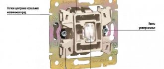
A changeover switch, or as it is also called marching, double, reversing, cross, is an element of the electrical network that inverts (translates to the opposite state) the switching of conductors connected to it.
A rocker switch is used to control a group or one lighting fixture from several locations.
In this material we will talk in detail about the principles and features of the operation of such switches, and also give the most common methods of connecting them.
Scope of application of changeover devices
Changeover switches are not used so often, but their role in organizing lighting cannot be underestimated. Imagine a situation where there is only one switch installed in a long corridor or at the beginning of a flight of stairs and you have to walk considerable distances in the dark to turn on the light.
Installing a pass-through switch in two directions is quite capable of solving this problem, and a changeover (cross) switch will become indispensable:
- in a three-level apartment - installed near the second floor landing;
- in a large corridor or hall - installed near each door, it will greatly facilitate movement in the dark;
- in the bedroom - you can install one near the door and two near the resting place, and you no longer have to get up to turn off the light.
You can also use a rocker switch to turn on lighting on the street or in the garage, controlling the lamp from the house, gazebo, terrace, etc.
When leaving the room into the corridor at night, the user can turn on the light immediately, rather than moving around in a dark room looking for a switch
Multi-position switches of modular type
The cam burst switch is the most common type of these devices, like other switches, it is used to control various types of electrical loads.
Cam switches
The scope of application of cam switches is quite extensive; here are some examples of their use:
- AC and DC control switchboards;
- emergency shutdown systems, automatic transfer of reserve, switching of operating modes of electric motors;
- control of transformer substations and lighting;
- equipment for substations (control of grounding switches, sectional switches, disconnectors, etc.);
- switching heating equipment modes (turning on, off, switching electric heating elements of the load);
- selection of operating mode of electric welding equipment, etc.
Cam switches consist of several packages (each responsible for switching one line) placed in one housing. The figure below shows the structure of such a package.
Cam Switch Package
Designations in the figure:
- a - fixed contacts (4 pcs.), to which wires are connected;
- b – a special protrusion “cam”, which allows you to hold and move the rod;
- c – group of movable contacts (there are two of them in this type);
- d – two guide grooves (allow the rod to make translational movements);
- e – two rods covered with an insulating shell;
- f – contacts (8 pcs.), usually made of an alloy containing silver;
- g – package;
- h – two threaded rods (fix the bag and the lid);
- I – rotor;
- J – four springs (return the rod to the closed position);
- k - shaft connecting the handle to the rotor;
- l – four screws for clamping cable wires.
Note that the batch switch (cam switch) can have several positions, including zero, that is, when the contacts are disconnected. The figure shows the state of the switch in the neutral position.
Schematic representation of the switch in the zero position
ABB switch in zero position mode
Note that all the main characteristics of the switches are indicated on the device case; the following are displayed there:
- switch type;
- rated current for which the switch is designed;
- switching diagram and table;
- protection class.
Below is a diagram and switching table shown on the housing of the SPAMEL rotation direction switch.
Scheme and switching table of the SPAMEL switch
Thanks to this table, you can clearly see in what position and which groups of contacts are connected.
Types of changeover switches and their markings
The choice of changeover switches has to be made based on a modest list of distinctive characteristics. They are produced by many well-known companies, including Legrand, ABB, Schneider.
Lever electrical equipment is considered more reliable and therefore is often used in factories and public places
Changeover switches are classified:
- According to the method of activation, they are divided into rotary, key and lever types;
- According to the installation method - for devices for internal and external installation.
You won’t find two-key cross-type toggle switches as such on sale. But you can use an Ultra series device from the well-known electrical equipment supplier Schneider Electric by taking two modular-type single-key crossover units and installing them in one housing. If these models are not available, two single-key switches are mounted side by side.
To control two or three groups of lighting fixtures, two or three-key pass-through switches are used, and cross switches, in most cases, are installed separately for each group of lamps
When choosing any electrical device, you must focus on its protection class from external factors - IP.
In most cases, in devices of this type, the IP is quite high and exceeds 40, which allows for use in rooms with traditional high humidity, as well as outdoor location under a canopy.
In rotary changeover switches, the contacts are closed using a special rotary mechanism. They cost a little more than keyboards, but are considered more reliable
In order to correctly connect electrical equipment, it is important to understand the symbols and diagrams printed on the back by the manufacturer.
This is how the diagram indicates a cross-type switch. The same diagram is applied to the device, the arrows show the location of the input and output contacts
If in a conventional switch the marking with the letter L is used to designate the incoming phase terminal, and L1, L2, L3 for the outgoing ones, then in the case of a paired switch the numbers 1, 2, 3, 4 can be used, and the incoming and outgoing terminals are indicated by arrows.
Manufacturers also sometimes put markings on the front side of the switch - for a walk-through switch these are two arrows in the form of a triangle, for a changeover switch - a grid
Next, we will look at the installation features and options for possible connection diagrams using the example of a household cross-type changeover switch complete with adapter switches.
Operating principle and features of changeover switches
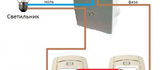
To understand the operating principle of a cross-type rocker switch, it is necessary to study the control circuit for lighting points of 3-5 points.
But since the crossover switch is always installed between the walk-through switches and is never used on its own, you first need to understand how the lighting activation and deactivation circuit works with regular and walk-through switches.
Three-point lighting control circuits differ from a two-way circuit only in the presence of a cross switch
So, the functions of a regular switch include opening and closing the circuit - when you press the upper half of the key, the light turns on, the lower half turns off. But the state of lighting in a circuit with two pass-through devices does not depend at all on the position of the keys of one of them.
Pressing a key only switches the connection from one circuit to another. In order for the circuit to close, it is necessary for both devices to make contact with one of the conductors laid between them.
A pass-through switch is also called a two-way switch. The diagram clearly demonstrates that the user, using any of them, will be able to turn the light on and off
The mechanism of different types of devices differs in the number of terminals:
- in the usual there are two of them;
- in the transitional there are three;
- in a cross connection there are four terminals.
The more complex the device, the more quality it requires. Therefore, the design of rocker switches, which have a large number of terminals, is distinguished by high strength, wear resistance, and corrosion resistance.
Most models have a high level of protection (IP) from negative external factors - dust, moisture.
If pass-through switches are always used only in pairs, then the number of changeover switches can be any - at least one, at least ten
Just like pass-through switches, crossover switches switch connections from one conductor to another. But their difference is that there are already two input contacts, not one, and their switching also needs to be controlled. The operating principle of the device is based on paired switching of contacts.
Connection diagram for pass-through switch
February 18, 2015. Category: Lighting.
Controlling lighting from two places is not a new idea, but it is actively used today. To implement this, pass-through switches are used.
What is the difference between a pass-through switch and a regular switch?
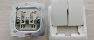
If you look at the pass-through switch from the side, you will not find any external differences. The significant and only difference between such switches and simple ones lies within their design.
A conventional single-pole single-key switch has two contacts in its design, fixed and movable. The moving contact is driven by a key that we press by hand and closes with the fixed contact. This closes the electrical circuit and supplies power to the lamp. There are also designs of two-pole single-key switches that essentially perform the same function as the previous one. Its difference is that the neutral wire going to the lamp breaks in the same way as the phase wire. This was done to improve security.
Figure 1. Schematic diagram for connecting single-pole and double-pole single-key switches
The pass-through switch has two fixed and one moving contacts. The moving contact is always closed with one of the fixed ones. When you press a key and move it from one position, for example, "off" to another position - "on", the moving contact also changes its position, opening with a closed contact and closing with an open one.
That is, the pass-through switch does not have an “off” position and it works not as a switch, but as a switch. Therefore, in technical literature and in manufacturers’ catalogs it is correctly called a switch. For example: “single-pole, single-gang, double-throw switch.”
Keep this in mind when you buy switches to assemble a control circuit from two places.
In addition to single-pole switches, there are double-pole and even three-pole switches. For ease of understanding, in this article we will use the expression not a switch, but a pass-through switch, since it is more often used among people.
Where is a similar lighting control system used?
The lighting control system most often considered is used in public and industrial premises, namely: in long corridors, tunnels, walk-through rooms, that is, in rooms where there are two doors equally serving as entrance and exit, in staircases and other places. In all of the above cases, pass-through switches are installed next to the doors.
If we talk about residential premises, then the installation location for pass-through switches can be, for example, the entrance door to the room and a place on the wall next to the bedside table. In this case, a person entering the room will turn on the light by pressing the pass-through switch located next to the door, and sitting on the bed, without getting up, he can turn it off with the second pass-through switch located next to the bed.
Using pass-through switches, you can control one luminaire or lamp, or a group of them. For each case, different types of pass-through switches are used (single-key, two-key, three-key). The goal that a person pursues when installing such switches is the convenience of light control and reducing energy costs.
Connecting a pass-through single-key switch
Figure 2 shows a schematic diagram of connecting pass-through switches designed to control one lamp or one group of lamps from two places remote from each other. As you probably already understood, a single-pole pass-through switch has two fixed contacts and one changeover contact. The changeover contact of one of the switches is supplied with supply voltage. The changeover contact of the second switch is connected to the lamp, and the lamp, in turn, is connected to the neutral wire of the supply network. The fixed contacts of the first switch will be connected by two separate conductors to the two fixed contacts of the second switch.
Figure 2. Schematic diagram for connecting a pass-through switch with one pole and one key
In the diagram, the position of the changeover contacts of both switches is the same, which corresponds, for example, to the lowered position of their keys. The electrical circuit is open. If we press the key of the first switch and move it to the raised position, then the changeover contact of this switch will accordingly also change its position and close the electrical circuit. An electric current will flow through the circuit (the direction of the current is shown by arrows), and the lamp will begin to glow. If you now press the key of the second switch and also change its position, the circuit will again be open and the lamp will go out.
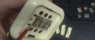
For a more visual representation of how the conductors are connected, Figure 3 shows a wiring diagram for connecting pass-through switches. The green circle is nothing more than a distribution box, inside which the wires are connected. The round pieces inside the box are soldered wires, made in the form of twists with welding, crimped with self-clamping insulating caps, connected with terminals or a screw connection. Everything else I think is clear.
Figure 3. Wiring diagram for connecting single-pole single-key pass-through switches
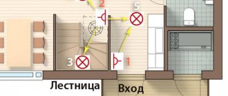
Figure 4 below shows a diagram of the arrangement of equipment and routing of wires. The connection of the wires in this case is made in two distribution boxes 1 installed above the pass-through switches 3. This was done in order to save wires. If we installed one junction box and assembled the circuit in it, we would have to lay two more wires from the box to the switch closest to us. If the supply wires were supplied from the side of lamp 2, then all connections could be made in one box without unnecessary wiring costs.
Connection options
Just as pass-through switches cannot be used individually, but are connected only in pairs, so changeover switches are used only with two pass-through switches. In this case, up to 10 cross switches can be used, and they will always be located between the pass-through switches.
In the diagram, the phase conductor is indicated in red, the neutral conductor in blue. A 1 - basic connection diagram; A 2 is another version of the connection diagram; B1 - wiring method, in which each element of the circuit is connected through a distribution box; B 2 - connection method using an old small junction box and a socket from under a dismantled conventional switch
There can be many options for circuits used for connection: installation is carried out through a distribution box or past it, several lighting groups are connected.
They will improve the system by installing centralized control.
The cross-type changeover switch device is always designed for one lighting group. If it is necessary to connect two groups of lamps, use either two switches or make up one of two separate blocks
Installation via distribution box
This is a traditional connection method, which has both disadvantages and advantages. The advantages include the ability to quickly detect damaged sections of wires in case of problems in the circuit.
In addition, this method involves the traditional laying of wires, which helps during subsequent repair or installation work to determine where the wires are laid and maintain the integrity of the electrical network.
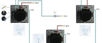
Connection diagram for pass-through and cross switches in a lighting control system from several places. L - phase conductor; N - zero
When installing electrical wiring from the junction box to the pass-through switches, three-core wires are laid. A two-core wire leads from the crossover switch to the feedthroughs.
The sequence of actions when connecting a circuit in which the wires pass through a junction box is as follows:
- A two-core phase wire from the electrical panel is inserted into the box. The neutral conductor of the supply cable is immediately connected to the neutral conductor of the lamp, and the phase conductor is connected to the common conductor of the first pass-through switch No. 1, to input terminal 1 (see figure above).
- The remaining two conductors of the three-core wire are connected to output terminals 3 and 4, which in the junction box will be connected to the two conductors of changeover switch No. 2.
- Install the middle changeover switch. The correct connection of the crossover switch conductors is indicated in the diagram drawn on the device itself.
The second pass-through switch is connected in the same way as the first, but the common conductor is routed through the junction box to the lamp.
Laying an electrical network for organizing lighting using distribution boxes is good because in the event of a malfunction it is easier to identify the damaged section of the electrical wire
If the connection in the junction box was made by twisting, all exposed areas are carefully insulated to prevent a short circuit.
This is done using electrical tape or heat-shrink tubing, which can serve as a marking for the conductors.
We also recommend reading our other material, where we talked in detail about installing a junction box. Read on for more details.
A professional connection is immediately visible - all wires are laid compactly and neatly in the junction box
Direct connection method
Connections are the weak link in any electrical network - this is where oxidation occurs. Regardless of whether it is side clamps or spring-type quick-release terminal blocks, they burn out first; the wire itself remains intact, since it is protected from burnout by a machine.
To minimize the number of connections, the connection is made without a junction box.
They also come to this connection method because users do not always want to see several junction boxes on their wall - these are additional elements that have to be hidden from view
How to install an electrical system without a junction box:
- A cable with two conductors is pulled from the electrical panel - phase and neutral. The latter leads directly to the lamp.
- The phase is connected to the input terminal of the pass-through switch. Two phase wires lead from the two output terminals to the cross wire.
- Two phase conductors are laid from the output contacts of the reversing switch and connected to the second pass-through.
- The common conductor from the second pass-through switching device leads to the lamp and closes the electrical network.
All wires must be marked during electrical installation work. Otherwise, next time, when carrying out electrical installation work, it will be difficult to identify their nature.
It will be quite difficult to fit all the conductors that are connected to each other in the socket box. Therefore, flatter and more compact terminals are used. You can also solve the placement problem by using large socket boxes - with a depth of 60 mm
You can hide distribution boxes in other ways. For example, by installing a box behind a suspended ceiling.
This option cannot be called a win-win, since in complex cases of breakdowns, the detection of a fault may not be limited to one box, and then you will have to remove the ceilings in more than one room.
Distribution boxes are also installed behind the suspended ceiling. In this case, they are all concentrated in one place, and access is provided by an inspection hatch
Check the correct connection like this: every time you press the key of any switch, including the cross switch, the state of the lighting should change - the light should turn off and on. Problems can arise if errors are made during the connection - the circuit is assembled incorrectly, the contacts are mixed up.
The cause of improper operation of the changeover switch can be eliminated only by thoroughly checking the connection directly at the installation site.
Household use
Using a two-position switch on a flight of stairs
In domestic conditions, a two-position switch is not used as often as its single-pole counterparts. But when using efficient lighting systems, there are cases in which it is almost impossible to do without these switching elements. We are talking about organizing control of a common light source from two or even three places in the house at once. This need arises in a situation when the light turns on at the entrance to a long corridor, and turns off at the exit from it. When installing toggle-type switches at both ends, implementing such a circuit is not at all difficult.
Another example of the importance of controlling a lighting fixture at two points is when there is a light switch at the entrance to the bedroom, and a switch near the bedside table. When you press the button of the device at the entrance to the room, a group of contacts is transferred to the power line of the illuminator located in its center (a chandelier, for example). When switching the second device located near the bed, other group contacts are triggered to turn it off.
It is important to note one feature of this inclusion: the order in which each switch is used is not fundamentally important. You can enter the corridor from either of the two ends, and turn on the light in the bedroom both from the door (at the entrance) and from the bedside table. Accordingly, you can turn it off both when you go to bed and when you leave the room.
Another possible option for the domestic use of two-position switching elements is to install them in home lighting control circuits from three places. In this case, you will need another switch, mounted in the middle of the serviced space or in any other functionally convenient place.
The additional device is switched on according to the so-called “cross” circuit, but in essence it is the same two-pole element. With its help, it is possible to transfer group control contacts from one direction to another.
Typical connection errors
Ignoring the markings and diagrams printed on the switches leads to connection errors and incorrect operation of the circuit. The most common problem that occurs, especially when installing pass-through switches, is the user incorrectly identifying the location of the incoming contact.
It may be located differently on different devices, so you must read the markings. All the subtleties of choosing pass-through switches are discussed in this material.
If it is not possible to determine the exact location of the incoming terminal, then test the device with a multimeter or an indicator screwdriver
When connecting changeover crossover switches, problems arise if paired wires from pass-through devices are connected to terminals located on the wrong side.
Most often, the device involves a cross connection.
You should always check the circuit before connecting. The input and output contacts of the changeover switch can be located differently
Lighting with cross switch in TN-S network
Connecting a crossover switch in a TN-S power network, which is characterized by the separation of the working (N) and protective (PE) zero, has some nuances. Unlike the old, not entirely safe TN-C system, the electrical network conducted according to the new standards uses 3 wires when supplying single-phase voltage, and 5 when supplying three-phase voltage.
The wire that performs the function of zero (N, marked in blue) comes out of the electrical panel, passes through the branch box and is connected to the zero of the lamp. The ground wire (PE, indicated in yellow-green color) is connected to the ground wire of the lighting fixture.
Laying electrical networks using the TN-S system significantly increases the cost of materials, but reduces the risks associated with the operation of electrical equipment
Operating principle and device
Two-position switch ON-OFF
A classic two-way switch or two-position switch belongs to the same category of devices as a regular single-pole device. However, if the latter simply closes and opens the power circuit, turning the load on or off, then the electric switch switches its contact from one load line to another in 2 positions. This is its fundamental difference from other switching elements, which naturally affects the device.
A two-pole device (unlike a single-pole analogue) contains in its design not two, but three groups of switched contacts. One of them, called the central one, is alternately connected to one direction or the other, supplying power to various consumers. A typical example of such a design is an ordinary toggle switch, which in most equipment is only half used - as a switch or switch. If this device uses the second direction, it turns into a changeover type device, disconnecting one load from the supply network and connecting another.
Based on the type of switched voltages, known samples of 2-position switches are divided into single-phase and three-phase models. More complex designs include products designed for several positions at once (they are called multi-position). Double-pole, double-throw switches belong to the same category of devices.
How to establish centralized lighting control?
The control network from several places has a significant drawback - all the switches involved in it do not have a fixed position. Therefore, it is impossible to determine whether the light in the room is on or not if there is no electricity. Installing a conventional switch in front of the first pass eliminates this problem.
To the already known connection diagram for changeover and pass-through switches, one more element is added - a regular single-key one. Place him in the same room or take him to the front door. When enabled, it will allow the system to operate as normal. When turned off, the circuit will be completely de-energized and, regardless of the position of the switches, the light will not light up.
An even better way to improve centralized control is to use a pulse relay. It has great functionality and allows you to control a separate group of electrical equipment or lighting throughout the house.