Almost all automated systems contain a device such as a limit switch, which is responsible for turning them off when the moving part reaches a certain point. In lighting control systems, limit switches are used as sensors. When programmed circumstances occur, they generate a signal.
We will tell you everything about the functional purpose and types of limit switching devices. The article we presented describes practical-tested wiring diagrams and lists connection rules. Features of marking are given and advice on selection is given.
Limit switch markings
Each of these switching devices is marked accordingly. By deciphering it, you can obtain all the information about a specific model of limit switch. If there is an entry VU222M on it, then it means that this is a limit switch of the VU222 series. The moving element is a modernized lever.
This block diagram shows the symbol of a limit switch intended for operation in control circuits operating from alternating and direct current with a maximum voltage of 660V
Let us decipher in detail, for example, the marking of the VP 15M4221-54U2 switch. It is equipped with one movable active element of the 15 series. It has one make contact and one break contact, equipped with a pusher with a roller. The level of protection is IP54 on the drive side, “U” indicates the climatic version, and number 2 indicates the placement category. The product complies with TU U 31.2-25019584-005-2004.
Contactless optical switches
BKVs of this type control objects that both block radiation and reflect it. When an object enters the space between the switch and the light source, the sensor interrupts the light output. The element responsible for this action can be a relay or semiconductor. The response radius extends up to 150 m.
Optical limit sensor
Proximity sensors operate in a wide temperature range - from -60 to +150⁰С. They can withstand pressures of about 500 atm and can be used in aggressive environments and even in conditions of increased explosion hazard.
Classification by principle of action
There are three main groups of limit switches: mechanical, non-contact, magnetic. The main function of all these devices is to automatically disconnect the working mechanism the moment its moving part reaches the set position. These switches serve not only to open a circuit, but also to connect it.
The operation of the circuit in the end sensors is coordinated in two ways: by direct action on the moving contacts and by positional control of them. In the first case they are called contact, in the second - non-contact. An example of contact limit switches are sensors responsible for closing car doors.
The photo shows the design of a track-type limit switch. Its main components are: cover (1), base (2), contacts (3), roller (4), lever (5), sealing strip (6), wire entry (7)
Sensors of this type can not only turn mechanisms on and off, but also establish the position of the object being monitored. These include float switches, as well as sensors that determine the fuel level. The signal for their operation is a change in resistance corresponding to a certain level of liquid.
The disadvantage of contact sensors in the presence of mechanical moving parts is a relatively short service life due to ineffective protection from moisture and dust. The advantage is simple design, installation and operation. Contactless switches are much more reliably protected from external influences. Their resource is also longer.
Mechanical type limit switches
The control of limit switches of this type can be roller or lever. They are triggered as soon as the control mechanism in the form of a wheel, button or lever experiences mechanical impact.
In this case, the position of the contacts changes - they can close or open. The process is accompanied by a signal - control or warning.
Most often, limit switches have two contacts - open and closed. There are single end devices, but they are rare. In any case, there are contacts in each case, and a working diagram with their numbers is shown on the panel.
The design of roller VCs provides for switching off by pressing the actuator on a button in the form of a small rod. Since it is connected to dynamic contacts, at the moment of contact the supply circuit opens.
The difference between lever switches is that their movable contacts are connected to a small lever by means of a rod or a rod. The action occurs when the actuator presses this lever.
The photo shows a mechanical limit microswitch KW4-3Z-3 with a pressure bar. It differs from the standard one in the stroke of the working element. It is used in CNC machines and 3D printers
In addition to standard end devices, there are microswitches. They work on the same principle, but their adjustment during installation requires greater precision due to the small stroke. To increase the working stroke, they resort to such a technique as including an intermediate element in the circuit - a lever with a roller.
This type of switches is used both in production and at home. A large number of control units are used in the elevator design.
Among them is a switch in the form of a sensor that limits the minimum and maximum height of the elevator, signals a rope break, gives a signal to open the door and performs many other actions. There are microswitches on the doors of many apartments that turn on the light in the room when it is opened.
In automobiles, such mechanical end sensors are included in alarm and lighting circuits. Their feature is the presence of one input with a positive potential connected to it. The housing is the negative terminal, pressed against a metal element on the car body that is free of paint.
This element is connected to the vehicle ground by a cable. The main condition is that the switch should not come into contact with a wet surface. Connect the end sensors when installing a car alarm using a diagram. Their outputs can be installed both on the doors and in the interior on lighting fixtures.
To turn it on when the door is opened, and turn it off when it closes, a short circuit to positive is performed. If there is illumination of the interior ceiling and doors, a block of limit switches is used, which performs various functions. As a result of the block being triggered, important sensors are blocked when attempting to open the locks.
Features of contactless limit switches
One of the varieties of limit switches is their non-contact modification (BVK). The communication of the devices is configured to trigger when a specific object enters the sensitivity zone.
These limit switches are adjusted to a specific material and a given size. As soon as an object with such parameters enters the sensitive zone, the amplitude of the generator oscillations is transformed
There are no moving parts in the device itself, and there is no mechanical contact between the object of influence and the switch element configured for it.
The BVK consists of the following parts:
- sensitive element;
- power key;
- component that analyzes the signal.
The distance at which the device begins to operate is set based on the modification of the sensor and the requirements of the process. The exclusion of both moving and rubbing elements significantly increases the reliability of these devices.
Contactless sensors, or proximity sensors as they are also called, have extensive functionality. There are two categories - switches and position sensors.
The first task of the BVK is to detect the position of an object. In addition, the sensor performs counting, positioning, separation, and sorting of objects. It can control speed, movement, calculate rotation angle, correct skew and perform many other actions.
In domestic conditions, contactless switches are still primarily used in lighting control. However, in the field of arranging Smart Home systems, it has a much larger scope of application and much more prospects.
Sensitive devices are used in industry, in the transport industry, as an element of automation, and in oil refining. Based on the principle of detecting approaching objects, BKVs are distinguished between inductive, capacitive, optical, and ultrasonic.
Inductive proximity sensors
They are tuned to materials both metallic and amorphous. Among those reacting to metal there are magnetic and ferromagnetic options. Inside the sensor there is a core - metal or magnetized.
The switch can receive power with a wide range of voltage values - from 10V at direct current, alternating - from 264 V. The output signal is created at 0.2 A in the case of direct current and 0.5 A in alternating current
If we describe the design of such a sensor in more detail, it consists of a converter that includes a copper coil located in a ferrite cup. Its functions include redirecting the vector of electromagnetic lines to the front part of the switch.
The oscillator in the circuit can be either with a fixed negative resistance or any other type. The magnetic field lines are oriented perpendicular to the direction of the current flowing through the turns of the magnetized core.
The alternating force field is caused by the alternating voltage at the core inputs. The next important component is the signal conditioner, which creates hysteresis and the range of action of the control signal. It includes a trigger controlled detector.
The diagram shows an inductive motion switch in action. Its main element is an inductor driven by a generator
The key to the operation of an inductive limit switch is the changes that occur when an object approaches or moves away. As soon as the voltage threshold exceeds the permissible value, the sensor is activated by connecting a trigger that opens the key.
Capacitive proximity limit switches
After the object appears, the vibrator circuit of the capacitive device is started, and time parameters are set. As the object approaches the sensor, the capacity of the latter increases, and the frequency generated by the multivibrator decreases.
As soon as the frequency threshold is exceeded, the device will turn off. Many models of motion sensors operate on this principle, turning off and on light bulbs when an object is detected in the sensitivity zone.
The block diagram of a capacitive sensor is similar to an inductive device: both models contain a generator and a detector.
The principle of operation of a capacitive type limit switch is based on changing the capacitance of the receiving element - the capacitor. In such sensors, the switching operation begins when dielectric and metal objects enter their field
In addition to the generator that generates the electric field, their design includes such basic parts as a demodulator. It acts as a converter of the amplitude of high-frequency oscillations with a simultaneous change in voltage. The next important component is the trigger, which is responsible for a certain signal level, switching and hysteresis dependence.
To increase the input signal to a set value, an amplifier is included in the capacitive switch circuit. The LED indicator monitors the settings and operation of the device.
An element such as a compound protects the switch from moisture and solid particles. A plastic or brass body protects everything inside it from mechanical damage. The kit also includes mounting hardware.
The switching element in this device is located on a capacitor and is a plate that interacts with a vibrator. The role of the threshold element is performed by a comparator connected to the vibrator. The latter, in turn, is connected to a frequency and voltage converter.
Capacitive limit switches react to solid materials, powdery, liquid, both electrically conductive and non-conductive
The difference between capacitive models and inductive ones is that the former react to air humidity and changes in density. The latter are insensitive to such influences.
Ultrasonic switch design
The design of ultrasonic limit switches provides for the presence of quartz sound emitters that form pulsed waves with a length of 100 - 500 kHz, and a receiver whose settings correspond to a certain frequency.
When the amplitude of sound waves changes as a result of maneuvers of a moving object, the BVK microswitch records the new values and, based on this, controls the output signals.
The operating principle of ultrasonic sensors is based on the change in time during which a sound wave travels from the sensor to the controlled object. The detection distance of such devices is quite large - up to 10 m. Their big advantage is that they can detect an object of any shape and color that reflects sound.
The operation of this ultrasonic sensor is based on a simple principle: as soon as a signal is received on one of its legs, the other receives a pulse with a length equal to the distance to the object
Such sensors are used to detect objects with a flat surface occupying a perpendicular position relative to the detection center line.
Inaccuracies in their work can cause:
- Sudden, high-power air currents that strengthen or weaken the wave.
- Sudden change in temperature. With a large amount of heat emitted by an object, the speed of the propagated waves changes.
- Deviation from the vertical of the angle between the horizontal plane of the object and the axis of the sensor. If this error exceeds 10⁰, the sensor does not operate.
- Angular outlines of the object. In this case, its identification is very difficult.
Vibrations propagate in solid, gaseous, liquid media, and the speed depends on the relevant parameters. Ultrasonic sensors have no moving parts, so there is no relationship between the number of cycles and the service life of the device. They are characterized by increased resistance to all kinds of external influences.
Optical contactless devices
BKVs of this type control objects that both block radiation and reflect it. When an object enters the space between the switch and the light source, the sensor interrupts the light output. The element responsible for this action can be a relay or semiconductor. The response radius extends up to 150 m.
This is a photo of an optical type end sensor. It determines the positions of the extreme points of movement of moving parts in 3D printers and CNC machines
Proximity sensors operate in a wide temperature range - from -60 to +150⁰С. They can withstand pressures of about 500 atm and can be used in aggressive environments and even in conditions of increased explosion hazard.
Magnetic end varieties
This type of switches, which are also called float switches or reed switches, is gradually replacing mechanical models. Their contacts change position when they are at some distance from the magnet. In this case, a signal is sent to the control circuit.
The reed switch contains one or two contacts made of a special material - a ferromagnet. The magnetic limit switch is small in size. It is placed in a housing made of plastic or glass, and mounted into an electrical circuit at its break.
The contacts in such a switch can be open, closed, or switchable. In devices of the first type, the contact closes when triggered. Normally closed contacts open in similar circumstances, and switched contacts behave according to the situation.
The choice of model depends on specific circumstances. Reed switches are used in the design of sliding gates. With their help, the structure is stopped when it reaches the extreme position when opening or closing.
Some float models are used as part of a security alarm at the entrance to a house. When the door is closed, the circuit is closed due to the influence of the magnetic field on the limit switch. The opening of the door provokes the movement of the magnet and the opening of the contact, causing the alarm to turn on.
When installing magnets, take into account their polarity. If installed incorrectly, they will not perform their intended functions.
The fact that there is no mechanical contact in this design is its advantage, which increases longevity. They are distinguished by the simplest structure, based on the interaction of magnetically controlled contacts with a conventional magnet.
Limit switch - device design and principle of operation
A limit switch is used to control and limit the movement of various mechanisms.
It must have the following characteristics: reliability of operation, safety for people and devices, high mean time between failures.
There are a large number of varieties of these switches: mechanical, magnetic, inductive. Each group is divided into subgroups. It all depends on where this or that device will be used.
Purpose of limit switch
Switching of 220V AC electrical circuits can be carried out using limit switches.
The action of the devices and their operation is determined by the contact contact of the end parts of the moving elements of the pneumatic drive, consisting of two-position pipeline fittings.
In addition, they can be used as limit switches that act as a position sensor in other devices, in systems used in industrial automation.
Design and operation of the switch KV-1, KV-2
The operating principle of the KV-1 (single-position, two-channel), KV-2 (two-position, single-channel) linear movement devices - limit switches is to use a permanent magnet printed circuit board with two reed switches, they are used as the main elements that switch the electrical circuit.
In addition to the board in the “limit switch” housing, the limit switch device contains a terminal block; in the main (first) housing there are two blind holes in which the rod goes; for KV-02 there are 2 rods. A permanent magnet, a magnetic circuit and a return spring are attached to the rod.
The action of the rod is reciprocating, with its help the magnet moves and closes and opens the contacts.
Rice. No. 1. Photo of the limit switch KV-01, KV-02.
Rice. No. 3. Drawing of the KV-1 limit switch indicating the overall and installation dimensions of the KV-01 and the location in the cable entry structure.
Limit switch KV-04
The design of the KV-04 (two-position, single-channel, rotary) is in principle similar to previous devices. Unlike a single-position switch, it is complicated by the presence of a rotary lever, with which you can adjust the angle of rotation of the axis clockwise and counterclockwise. Thus, the reed switches are switched.
Rice. No. 4. Drawing with dimensions of switch KV-04
The adjustment occurs by changing the cams located on the washer; they act on the levers, when turned, the magnet moves, switching the reed switch.
Fig. No. 5. Schematic electrical diagram for connecting the KV-04 limit switch.
Rice. No. 6. Photo limit switch KV-04.
Non-contact limit switches
Limit or, as they are also called, travel switches are non-contact, they operate based on the use of electromagnetic relays, as well as on the use of logical elements, the operation occurs without influence from the moving part of the device.
Non-contact limit switches are divided into two main types according to the principle of operation and the effect on the sensitive element:
- Mechanical impact.
- Parametric influence, due to changes in the physical parameters of the converter.
Parametric switches are divided into the following types:
- Inductive.
- Capacitive.
- Optical.
The connection of such devices is based on the use of a 2- and 3-wire circuit. In the case of a 3-wire circuit, power comes through a special wire.
Rice. No. 7. Contactless limit switches (sensors).
Non-contact limit switches are subject to increased requirements for operational reliability, because such devices have to operate under difficult conditions.
The location of these devices is in the working area of machines and assemblies, where they may be exposed to significant high temperatures, may be subject to shock and operate under the influence of strong vibration.
They can also be under the influence of a strong magnetic field, they can be affected by various, including aggressive liquids and contaminants.
Particularly important is the high requirement for increased switching frequencies, especially when used in complex technologies, for example, machine lines operating in automatic mode, complex transport systems, metallurgy and foundries.
What are limit switches made of and how are they connected?
I'll start, perhaps, with push-button switches. Their contact group, of course, is the most common: a pair of fixed-type contacts, between which there is a moving contact. The moving contact is connected to a rod extending outward from the device body. It is on this rod that the controlled object (door or gate) presses.
Lever-type switches are designed in almost the same way, with the difference that (as mentioned above) the moving contact is controlled by a lever, which is connected to the latter through a rod or rod.
Float switches of the usual type are a float mounted on a vertical pin, at the end of which a waterproof microswitch is attached. When the float reaches the highest point, it presses on the microswitch pin, turning off the power supply to the actuator (pump). Another similar microswitch is located at the lower point of the pin, turning off the pump when the lower liquid level is reached (thus preventing the pump from running without liquid).
Another type of float switches (magnetic) is designed as follows: an ordinary permanent magnet is fixed on the float, and the role of movable contacts is played by reed switches (sealed magnetically controlled contacts).
Slide-type switches consist of a pair of pointer sliders that are threaded to a rod. Each of the sliders is associated with its own sensor (the role of sensors is usually performed by microswitches), which signals that the corresponding slider has reached its extreme point. The big disadvantage of such limit switches is the need to adjust them manually (which is a very painstaking and time-consuming process).
Magnetic limit switches (like similar float-type devices) are based on a reed switch (sealed magnetically controlled contact). The device that controls such a contact is an ordinary permanent magnet enclosed in a plastic case. They are installed like this:
- A permanent magnet is attached to the moving part (door, hatch cover, window sash);
- The second housing, in which the reed switch is located, is fixed to a fixed part (door jamb, window or hatch frame);
- The reed switch contacts are included in the controlled circuit.
As a result, when the door is closed, the reed switch contacts are closed and power is supplied to the controlled circuit. When the door is opened, the permanent magnet leaves the magnetic engagement with the reed switch, as a result of which it opens, interrupting the power circuit of the controlled device. There are, however, reverse-acting switches, in which, when the magnetic influence is lost, the circuit closes. The only disadvantage of this type of device can be considered only that they are capable of working only with small currents.
Almost all limit switches are connected to an open circuit in the controlled circuit. As soon as the float switches are connected to the special contacts of the pump control device with which they are working.
In addition, all limit switches are divided into 3 groups:
- Normally closed;
- Normally open;
- Switching.
Depending on the characteristics of the electrical circuit, one or another type of limit switch is used.
Let's finish. I tried to answer the question in detail: what is a limit switch. Write, I will be glad to listen to your opinion. Check out other articles and sections on the site map. All the best!
Types and scope of application of limit switches
Push-buttons, like lever ones, are used mainly for turning lighting on and off in various rooms that do not require constant lighting. Such premises can be cold warehouses, basements (where the limit switch is controlled by the basement lid). In addition, limit switches of this type are used to control the position of the entrance hatch on crane beams (the crane cannot be turned on if the hatch is open).
Float-type limit switches are used where it is necessary to control the level of liquid filling a certain container. For example, such switches are successfully used to automatically control pumps that pump out water from wells that fill the main reservoir of the water supply system of small (for example, country) villages.
Float switches, whose operation is based on the operating principle of a magnetically controlled contact (reed switch), are also used where it is not possible to use conventional contact groups (for example, in containers with flammable and explosive liquids).
Slider limit switches are used for devices such as overhead gates and roller curtains.
Magnetic type limit switches (the main element of which is a magnetically controlled contact) can be used almost anywhere. This is due to the fact that such switches are absolutely safe to operate (their working contacts are completely protected by a bulb from which the air has been pumped out). Basically, these switches are used in security systems, as door opening sensors (due to the fact that the reed switches included in them are designed for a low switching current).
Pros and cons of proximity switches
A contactless switch is an alternative and at the same time a special case of a touch switch. It works on infrared radiation and allows you to turn on the backlight with a wave of your hand, i.e. without contact. The design is based on 2 elements: an emitter and a receiver. The switch reacts when any object appears within 2-7 cm of it. Such models are used in places where an important condition is the absence of hand contact with surfaces and objects.
When choosing contactless switches, it is necessary to take into account the profile material to which the LED strip will be attached. If it is aluminum, then you should avoid options with the chip located at the bottom and the power switch at the top. Such a switch cannot be attached to the bottom surface of an aluminum profile. It is only suitable for plastic. In the case of aluminum, you need to choose switches with a flat and smooth bottom base.
Another disadvantage of proximity switches is their width. Usually it is a couple of millimeters larger than the LED strip itself. Other important features:
- To operate the switch, you need to cut a window in the diffuser.
- The mode automatically turns off the backlight when the voltage suddenly disappears, and turns on when it appears. This is not typical for all switches, but it is worth clarifying this nuance before purchasing.
Thus, contactless switches have one serious drawback - lightning-fast reaction, so it is important to choose the right installation location
Problems and solutions
The design of a mechanical type HF is not difficult, however, malfunctions sometimes occur during operation. They are usually associated with burnt contacts or installation errors:
Table 2. Common problems with mechanical limit switches.
| Malfunction | Probable Cause | Elimination method |
| Breakdown of the switch to ground or unacceptable decrease in insulation resistance | The wire touches the housing, water enters the housing | Tighten the screws of the contact outputs. dry the switch |
| No contact | Burnt or burnt contacts | Clean contacts, reconnect burnt contacts |
| Trigger point spread | Play in the fastening of the switch or the entire device | Tighten the screws securing the switch or the entire device |
Video - Repair of limit switches on automatic gates
Mechanical limit switches perform simple but important tasks. Failure to operate the device can lead to accidents, destruction of equipment and injury to people, so the requirements for the reliability of the design are strict. Existing types of HF demonstrate reliable and trouble-free operation, ensuring the stable flow of technological processes or the safe operation of general-purpose equipment.
Installation and connection - step-by-step instructions
Connecting mechanical type limit switches is not difficult and is no different from the installation method of a standard device. A phase break connection is made to contacts of the required type (normally closed or open). The difficulty lies in the installation and adjustment of the HF, which requires correct location on the supporting structure.
It is necessary to install the device body so that the roller is in contact with a given element of the moving part, but does not protrude too far forward, risking breaking. If the moving structure is large in size and weight, it can vibrate during movement, which must be taken into account when adjusting the position of the roller.
For such structures, it is more correct to use switch models with an adjustable lever to adjust the position of the roller in place. Let's consider the procedure for installing HF on sliding gates. To work you will need:
- Welding machine.
- Screwdriver, set of wrenches.
- Pliers.
- Bulgarian.
- Roulette, ruler.
- Point probe for identifying phase wires.
Step-by-step instruction:
Step 1. Mark the extreme positions of the leaf when the gate is closed and open. Weld metal platforms on the supports (guides) for installing the HF. At the same time, it is recommended to secure the metal pipe into which the wire will be placed.
We install a place for limit switches
Step 2. Place the sash in its extreme position and mark the centers of the holes for the bolts on the support platform. Perform the same steps on the second site. Drill holes and secure switches.
Step 3. Unscrew the caps and connect the wires, previously tightened into the pipe with wire. Connect the wires to the control panel and check operation. Adjust the position of the switches and, if necessary, install additional stops to ensure reliable interaction of the rollers with the moving sashes.
Connect and check functionality
Manufacturers and models
Limit switches are used in all areas of industry and many other areas of activity. The demand for these devices has aroused great interest from manufacturers of electrical products. There are many companies producing limit switches of different types. Let's consider the most popular models and types of HF:
Limit switch with Schneider roller
Schneider Electric is a French company that has been in business for 185 years. The company is engaged in the development and production of a wide range of electrical products. The factories of this company were also built in Russia, which made it possible to reduce the price and make the products accessible to the mass buyer. Schneider limit switches are reliable and versatile devices that ensure trouble-free and durable operation. The company produces the following types of mechanical HF:
- Push-button.
- Stock
- Roller rods.
- Roller lever.
- Roller with adjustable lever.
Schneider limit switches
Limit switch with roller VP15K21
VP15K21 is a series of limit switches intended for industrial use. They are designed for operation under the following conditions:
- Direct current - up to 440 V.
- Alternating current - up to 660 V.
- Rated thermal current - 10 A.
- Rated insulation voltage is 660 V.
Rod and lever types of semi-instantaneous and direct action switches are available.
Table 1. Characteristics of limit switches of the VP15K21 series.
| Switch type | Number of poles | type of drive | Response speed |
| VP15K21A(B)111 | 1 | Pusher | Direct action; |
| VP15K21A(B)211 | 2 | ||
| VP15K21A(B)121 | 1 | Pusher with roller | Semi-instant action |
| VP15K21A(B)221 | 2 | ||
| VP15K21A(B)131 | 1 | Lever with roller | |
| VP15K21A231 | 2 | ||
| VP15K21B231 | |||
| VP15K21A(B)161 | 1 | Lever adjustable length | Semi-instant action |
| VP15K21A(B)261 | 2 | ||
| VP15K21A(B)191 | 1 | Lever with roller of adjustable length | |
| VP15K21A291 | 2 | ||
| VP15K21B291 |
Options are available in sizes and design types that can handle complex tasks within existing process conditions.
Brief overview of some sensor models and their features
TM-510R.05, TM-510R.06
TM-510R.05, TM-510R.06 are assembled on the basis of TM-510 pressure gauges, and after installing the electrical contact attachment they become full-fledged ECM.
These ECM models use contacts with magnetic compression, which allow switching high currents with high breaking power of the contacts, compared to devices with sliding contacts.
EKM TM-510R.05, TM-510R.06 are characterized by a reliable electrical connection under dynamic loads.
Main characteristics:
- Two-pin electrical circuit;
- Maximum possible voltage ~380 V;
- The maximum possible current is 1 A;
- The maximum possible breaking power of the contacts is 30 W;
EKM100Vm
EKM100Vm is an electric contact pressure gauge on microswitches, designed to close or open an electrical circuit when a specified pressure limit is reached. Provides visual indication of monitored pressure.
If necessary, it can be equipped with additional options:
- Lugs, bends or impulse tubes;
- Taps and valves;
- Gaskets, adapters, dampers, etc.
Model EKM100Vm has the following characteristics:
- Possible measurement range up to 4 MPa;
- Accuracy class 2.5;
- Case diameter 100 mm;
- electrical contact group V version according to GOST 2405-88.
Technologies do not stand still, everything is being improved, including the designs of measuring instruments.
For example, modern digital sensors EKM-1005, EKM-2005 from the manufacturing plants Teploklimat, Teplokontrol and Elemer will very soon replace outdated pointer instruments. These are electronic indicating modern intelligent contact pressure gauges with both discrete and analogue outputs (4-20 mA).
They are already in quite high demand on the market.
Therefore, no matter what characteristics the device has, sooner or later a new one will appear, more convenient and useful in operation.
Limit switch device
The design of any such device consists of:
Cases. It can be made of dielectric or conductive material, depending on the design. The moving part with the help of an impact on which the contact group is pressed. There is no moving mechanism in reed switches and non-contact limit devices. Contact part. Can contain both NO (normally open) and NC (normally closed) contacts
When choosing a limit switch, you should pay attention to the voltage and current that will flow through the contacts. Since the duration of proper operation of the switch directly depends on this. It depends on what mechanisms it is intended to control.
It depends on what mechanisms it is intended to control.
Mechanical
Mechanical limit switches come in different designs, which determine their scope of application.
Their main types:
Most often they are used, of course, for production purposes, metallurgy, mechanical engineering, and construction. They are often equipped with a rubber seal and contain a group of contacts that include both make and break contacts.
One of the varieties of this kind of limit switches is called microswitches and their operating principle is similar to conventional ones. But the sizes and currents are much smaller. The working stroke of such elements is measured in millimeters, and therefore they are used using an additional lever, which can be equipped with a small roller. Therefore, installing it will require careful adjustment of the trigger.
Contactless
All these contactless switching devices are divided into:
- Capacitive - based on interaction with the human body. The fact is that when a person approaches it, an electric capacitance arises as a result of which the multivibrator circuit installed inside the limit switch is activated. The closer the human body approaches, the greater the capacitance and the lower the pulse frequency. This element is highly sensitive. The main function is performed by a plate tightly connected to the capacitor.
- Inductive - this is an electronic proximity switch that responds to the movement of magnetic material. Depending on this, such a sensor is equipped with a metal or non-magnetic core. When an object that is set to trigger approaches or moves away, it generates electrical impulses that are processed by a threshold element, and a signal is given to close or open the key.
- Optical is a special type of limit switches, which is equipped with an infrared LED and a special transistor that captures this signal (phototransistor). The optical element works regardless of natural light. When the LED beam is interrupted, the photocell will close, thereby turning off the actuator in whose circuit it is connected.
- Ultrasonic. Here quartz sound emitting elements are already used. They can also be used as motion or volume sensors. When it appears within its range of action, the amplitude of a sound signal of a certain frequency, often inaudible to the human ear, changes.
On the basis of these switches, all kinds of sensors for monitoring bulk and liquid materials, dispensers, etc. are manufactured.
Magnetic
An electromagnetic limit switch (reed switch) responds to a constant magnetic field. Often contains one
Automotive
Such devices used in cars are often used for lighting and alarm circuits. By and large, this is a mechanical limit switch. Structurally, it is made with one terminal to which a positive potential is connected. The negative terminal is considered to be the housing that is clamped to the metal element of the car body.
In this case, you need to ensure that the part of the body where the limit switch is installed is cleaned of paint.
Often equipped with several groups of normally open and closed contacts.
Pneumatic
A pneumatic limit switch is a device that can stop the flow of compressed air or other gas by pressing a control button or lever. At the same time, there is another type of these switches, which operates when a certain pressure in the system is reached.
I would like to remind you that you should connect or disconnect limit switches to the electrical circuit when the voltage is completely removed. After that, the voltage indicator will make sure that there is no voltage, and metal cases must be grounded.
Application area
Push-button and lever-type limit switches are used to turn lighting devices on and off in various buildings that do not require continuous lighting. These buildings can be all kinds of warehouses and basements.
Float types are used to control the level of liquid in a tank. In most cases, the devices are used at pumping stations.
Slide-type switches are used in lifting gate mechanisms.
Magnetic switches have gained the most popularity and are used in almost all areas of activity. They are safe to use and reliable in operation. Limit switches are used in security systems and in motion sensors. In addition, using such devices you can open and close doors from a distance.
Varieties
Devices are classified into the following groups.
By the nature of the action
- Normally open contact. Under the influence of a magnetic field of a certain strength, the contacts close and current flows through the circuit. After the end of the action, elastic forces return them to their place.
- Normally closed contact. The external magnetic field must generate such a tension that the resulting repulsive force overcomes the elasticity of the contact pair.
- Switchable contacts. The option has three contacts for connection: two are made of magnetic material, and one is non-magnetic. The first two are mutually attracted and commute one of the electrical circuits. In the absence of magnetic fields, the magnetic contacts (one of them) switch to non-magnetic ones and the circuit is re-switched.
By type of design
- Dry. This is a reed switch with a vacuum flask and contacts located in an environment of inert gases. When closing, contact bounce cannot be excluded (uncontrolled presence or absence of contact of their elastic working surfaces).
- Wet. In such devices, a drop of liquid metal, mercury, is added to the contacts. During elastic vibrations during contact closure, it fills the space between them and does not allow the electrical circuit to break.
Device types
Experts divided these devices into three large categories, in particular, they are:
- Mechanical . They are launched upon contact with a lever or wheel, in which case the contacts close or open, and warning and possibly control signals are sent.
- Contactless . They are triggered when any metal objects or other objects to which switching has been configured approach.
- Magnetic . It is activated by approaching a magnet to a certain distance. They are also called reed switches.
Magnetic devices
The magnetic switch includes a special non-contact element (reed switch) that operates to close or open under the influence of a permanent magnet field.
Additional clarification. In a number of industrial models, the control action is generated by an electromagnet after a current pulse is applied to it.
Due to the absence of moving mechanical components, the reliability of these devices increases significantly, and the response life increases by an order of magnitude. Other advantages of switching devices based on reed switches include:
- Ease and simplicity of installation;
- Low cost;
- High performance.
Taking into account all these advantages, reed switch elements are widely used in various fields of electrical engineering and industrial production, and are also in high demand in everyday life (see figure below).
Reed switch
Their main purpose in everyday life is remote control of mechanisms responsible for the position of various objects in space (door leaves, in particular), carried out magnetically. In any living conditions, this element works quite reliably, and its functionality is not affected in any way by climatic factors.
A reed switch device, in which a permanent magnet is used as a control element, is slightly less reliable. Its movement introduces an undesirable mechanical component into the control process, which significantly increases the likelihood of errors.
In addition, the operating life of these devices is significantly lower than that of electromagnetic reed switches.
Principle of operation
The limit switch works in different ways: to supply or cut off voltage. This can be either a direct mechanical effect - push, touch, pressing, or the effect of electromagnetic fields, ultrasound or infrared radiation on special elements included in the design of the switch.
Sensory ones, for example, react to an object entering the radiation spectrum of rays, capacitive ones - to the approach of a person, mechanical ones - only to direct physical impact.
Regardless of the functional features, a group of contacts that control the required range of motion is always activated.
At the same time, it is important to correctly configure and install the limit switch so that it does not start prematurely, does not miss a signal, or breaks when a working mechanism “runs into” it.
Types of switches for home (domestic use)
The various types of switches used in everyday life must be convenient, safe, and have an attractive design. They differ from each other in types and types. Depending on the installation method, the switch can be built-in or installed externally. Nowadays, a rotary key is most often used as controls; such switches are common in Europe.
Types of switches for the home
In the USA they prefer to use lever-type switches (toggle switches), apparently not wanting to break away from tradition. But this is now, but in the old days, when Thomas Edison just made his invention, rotary switches were used. They were known throughout the world in the first half of the 20th century and switched up to several circuits in 3–4 positions (batch switch). Package switches are still used in many old utility panels.
To turn on the lamp, use a single-key switch; for chandeliers, use a two-key or even three-key switch. For rooms such as the toilet and bathroom, use a double light switch. Let us add that in our age of advanced technology, many switches with additional functions have appeared. These are the functions:
- Illuminated switch for night time
- switch with shutdown timer.
- Switches with brightness control.
If everything is clear with the first type of function, then the second is used to save light in small rooms (closets, bathrooms) where people enter for a short time and forget to turn off the lights. And the third can be used together with those lamps that support the dimmer function (dimmer). Sometimes they are included in the kit, since this type of device has not yet been standardized.
Unusual types of switches
A light switch with a motion sensor is another way to save electricity and is very convenient. The light turns on if the infrared sensor detects human movement within the sensor's field of view. Repeated motion may turn off the lights, or a timer may do so after motion has been detected. A switch with a motion sensor does not require any action from a person; his presence is sufficient.
There is one so-called smart switch, this is a clap switch. The way it reacts to noise, it can turn on involuntarily. Inside it there is a microphone, which is also an amplifier and a microprocessor device in order to recognize the nature of the sound. It may not work the first time, as it stores the sound from the user in memory for later comparison.
And there are such things
The floor switch is made in the form of a button with a locking mechanism. It can be turned on by pressing your foot with little force, and is designed in such a way that the weight of your foot will not damage it.
The ceiling switch is also a button with a lock, to which the force is transmitted from a lever with a cord attached to it. The mechanics are hidden behind a decorative cover. To turn it on or off, you need to lightly pull the cord.
What does the marking say?
Contactless switches are supplied to the market by various manufacturers. Among them are Western, domestic and Chinese companies
When purchasing, it is important to pay special attention to the quality of the units and the reputation of the manufacturer.
Due to the seriousness of the regulated processes, which are controlled by various modifications of sensors, you should only choose products that have accompanying documentation - instructions with installation diagrams, operating conditions and a list of technical parameters.
On the body of the device itself, manufacturers indicate its characteristics in the form of a set of letters and numbers - mark
Among these designations, some important information is encrypted, which is used when choosing the right model. Not all indicators can fit on a small area of the switch
The rest that are important to the consumer are contained in the user manual
Not all indicators can fit on a small area of the switch. The rest that are important to the consumer are contained in the user manual.
If the model you like does not come with instructions, then you should not buy it - it may be a fake. Moreover, some of the necessary parameters will remain unknown, and you cannot take the seller’s word for it.
All manufacturers are required to provide technical specifications to the end consumer. This requirement is prescribed by part 5-2 of GOST on low-voltage non-contact equipment mentioned above
Each company that produces switching devices for electrical circuit control has developed its own designation system. Its decoding is given in the catalog, which also contains the range of products offered.
An example of product labeling from the company AS Energia. The remaining parameters of the models are located in the instructions supplied with the kit.
The need for marking did not arise by chance - there is a wide variety of switches. In addition, they can be classified according to various principles.
For example, depending on the function performed during switching, devices are divided into the following categories:
- switching on (NO) – A;
- shutdown (NF) – B;
- switching – C;
- programmable option – P;
- other – S.
Depending on the installation method, sensors can be recessed, non-recessed, and others.
Sometimes manufacturers prefer to indicate a long code that describes the maximum parameters of the product, including the location of the sensitive element, the presence of an indication, climate control, etc.
If the company uses the marking principle recommended by GOST, then the inscription on the switch will, for example, look like this:
U3 A30 A D2
Where:
- U – ultrasonic method of detecting an irritant. The rest correspond to other Latin letters: I – inductive, C – capacitive, D, R and T – direct, reflective and barrier photoelectric, respectively;
- 3 – installation method is different;
- A30 – shape and diameter, which in this case means cylindrical with a thread with a diameter of 30 mm;
- A – element switching function, which means switching on (NO);
- D – number of wires for direct or alternating current output, which corresponds to two connectors for direct current;
- 2 – plug-in connection method.
In total, there are 4 combination options, among which one corresponds to ribbon wires, two is considered above, three corresponds to a clamp, and four corresponds to another method.
In modifications that require the presence of a wire, the manufacturer puts the characteristics on a label that is attached directly to the cable. It may also indicate the degree of protection, recommended voltage, etc.
Among the conscientious manufacturers are ZAO Sensor/Sesor, the German company Fotoelektrik Pauly, NPK TEKO, PKF STRAUS, ZAO Meander, the companies OWEN and SKB IS, NPP PRISMA from Yekaterinburg and others.
Many of them offer the service of manufacturing VBs with the parameters required by the consumer - to order.
We also recommend reading our other article, where we described in detail the different types of light switches. Read on for more details.
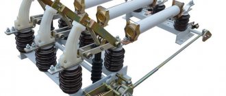
Features of a major overhaul
Overhaul of an oil switch may include the following work:
- Opening the circuit breaker, disassembling, disconnecting the tires.
- Draining oil from pots.
- Disassembly, cleaning, lubrication, repair, drive adjustment.
- Cleaning, repair, testing, replacement of insulators.
- Cleaning contact conductive surfaces.
- Trial.
- Measurement of pole insulation resistance.
- Testing of insulators.
- Measurement of busbar transient resistance.
- Adjustment of inclusion.
- Lubricating the jaws for a softer connection of the switch to the busbars in the cell.
- Assembling the switch after repair, adding oil.
- Removing dust, dirt, oil from tires and pots.
- Tightening loose tire bolts.
- Cleaning the workplace after completion of all work.
Major repairs are carried out by strictly specially trained personnel who have all the necessary approvals and permits to work in installations and substations with voltages of 6 kV and above.
The work is carried out under the supervision of a responsible person with an electrical safety group of at least 5. Unauthorized people should not have access to the work site, and the workplace itself should be fenced, warning and prohibition posters should be posted.
Major repairs and testing of oil switches are carried out, as a rule, once every 6 years, with intensive use much more often.
After each emergency shutdown of the device, high-voltage tests are carried out before turning it on again.
Design features of a limit switch with a roller
A design of this type is one of the options for implementing a push-button type, only with a modified button. Installing a roller can significantly expand the functionality of the device. If the button can be pressed only in the axial direction, then the roller will respond to any impact - axial or tangential, the main thing is that the vector of this impact is in the plane of rotation.
Limit switch device
The spring-loaded rod on which the roller is mounted is a movable element on which two pairs of contacts are installed - normally closed and normally open. When pressed, one pair opens and the other closes. This design is usually called the plunger type KV.
Limit switch type plunger-roller
It is used primarily on lifting mechanisms and devices with vertical movement of moving parts. For horizontal elements it is used to a limited extent, only when the accuracy of the impact and limited effort are guaranteed.
There are lever roller designs. The roller is mounted on a rotary lever, which, when turning, closes the contact group inside the housing. This design is convenient in mechanisms where it is impossible to precisely adjust the force and range of contact with a moving element due to high inertia, vibration, and uneven movement.
Lever limit switch
The risk of destruction of such a device due to too sharp or intense contact is much less than when using a plunger-type limit switch. They are usually installed on massive and large moving elements with increased inertia - elevators, escalators, trolleys, mine elevators, sliding gates of hangars, etc. Sometimes such structures are called limit switches, since they have the ability to be triggered by moving elements passing without stopping.
There are KV models with adjustable lever length. They allow the length of the roller support to be changed, which expands the capabilities and scope of the device.
Roller limit switch with adjustable lever
There are also designs where a lever is added as an additional element to increase safety. If you unscrew it, the HF takes on the appearance of a regular push-button device. Most microswitches have this design.
Microswitches
Door limit switch
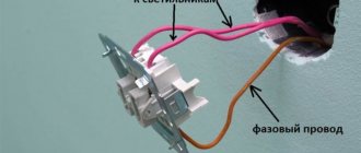
As an example of a limit switch on a door, we will use model 4313WD. The model is used to control light in furniture swing doors. The circuit is closed and opened by pressing a button.
The switch is held on the furniture by four self-tapping screws. Installed on the mounting surface inside the furniture so that the door presses the button. This ensures that the light is off when the door is closed. As soon as the door opens, the light turns on.
The system operates on 220 Volts. Current strength - 2 Amperes.
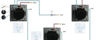
Operating principle of a pass-through switch
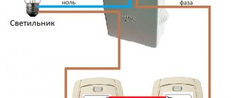
Unlike the usual models of two- and one-key switches for turning on lighting, pass-through switches provide two on positions. To operate the circuit, two pass-through switches are used, with which you operate the lighting lamps.
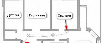
A schematic diagram of the operation of such an electrical circuit is shown in the figure below:
Figure 1: operating principle of a pass-through switch
As you can see, in the diagram, the phase wire is connected from the electrical wiring to the switches, and the neutral wire is led directly to the lamp or other lighting equipment. If you trace the connection from the distribution box, the phase is supplied to the input of the first pass-through switch. Next, two independent wires connect the terminals A and B of the first device to the terminals of the same name of the second switch. From the output terminal of the second switch, the phase is supplied to the lamp output. The second terminal of the lamp is connected by the neutral wire.
Of course, the above connection diagram requires additional cable costs to connect the switches to each other, but its functionality more than justifies it. Due to its design features, such a switch does not break the circuit in any position, so it is more correct to call it a switch.
In everyday life, due to the use of such switches on staircase landings to disconnect flights from different points, they are also called marching switches.
If you decide to implement such a scheme at home or in the office, but do not want to overpay for a pass-through switch, it can also be made from a cheaper two-key device. Next, we will look at two techniques that will allow you to make a pass-through switch with your own hands.
Connection diagram for a pass-through switch with 2 places
The circuit of a pass-through switch from two places is carried out using two pass-through single-key devices that work only in pairs. Each of them has one contact at the entry point, and a pair at the exit point.
Before connecting the pass-through switch, the connection diagram clearly displays all the stages; you should de-energize the room using the appropriate switch located in the control panel. After which it is necessary to additionally check that there is no voltage in all wires of the switch. To do this, use a special screwdriver.
To complete the work you will need: flat-head, Phillips and indicator screwdrivers, a knife, side cutters, a level, a tape measure and a hammer drill. To install switches and lay wires in the walls of the room, appropriate holes and grooves must be made in accordance with the device layout plan.
Unlike conventional switches, pass-through switches have not two, but three contacts and can switch the “phase” from the first contact to the second or third
Connection procedure and specifics
Connection diagram
Although the limit microswitch itself is designed quite simply, it can be used in technological equipment rich in electronics. It follows from this that it should be connected by an experienced specialist who is well versed in switching circuits of electronic components.
A typical example of such a connection is the installation of a mechanical switch in a typical 3D printer, during the operation of which it is necessary to fix the extreme position of the carriage. The mounted switch has 3 contacts with the following designations: COM, NO, NC. In the open state, the first and third terminals have a voltage of +5 Volts (while the second contact is reliably grounded). When the movable carriage reaches its extreme position, a connection appears between COM and NC, after which it locks and rebounds by approximately 2 mm.
Such a sensor is connected via two conductors in red and black insulation. When installing another type of switch (with an indicator), a more complex circuit is used, in which another conductor is provided - in green insulation. When the push-type microswitches in the printers are triggered, the LED lights up and a characteristic click is heard. Its connector, located on the switching board, has special designations:
- the red wire is marked as V (+5 Volts) and is used to connect the corresponding voltage;
- the black conductor is connected to point G (or ground);
- The green bus is set to S (signal).
The same signs are also present on the optical limit switch connector, which more accurately fixes the position of the carriage.
It works completely silently, reaching the extreme position is accompanied by LED indication. Its disadvantages include the possibility of failures due to heavy dust or exposure to direct sunlight.
Manufacturers and models
Limit switches are used in all areas of industry and many other areas of activity. The demand for these devices has aroused great interest from manufacturers of electrical products. There are many companies producing limit switches of different types. Let's consider the most popular models and types of HF:
Limit switch with Schneider roller
Schneider Electric is a French company that has been in business for 185 years. The company is engaged in the development and production of a wide range of electrical products. The factories of this company were also built in Russia, which made it possible to reduce the price and make the products accessible to the mass buyer. Schneider limit switches are reliable and versatile devices that ensure trouble-free and durable operation. The company produces the following types of mechanical HF:
- Push-button.
- Stock
- Roller rods.
- Roller lever.
- Roller with adjustable lever.
Schneider limit switches