The essence of the collector
The main feature of a water heated floor is the coolant; the water gradually moves to the heating circuit and gives off part of its energy.
That is why the heating of the floor occurs with the release of heat to the air that is mixed inside the room, and it, as is known, is directed from the bottom up. A number of devices are responsible for supplying warm water to the circuit and intensity:
- the valve is considered the main one;
- a pump must be present;
- collector.
All control of water distribution is carried out using a flow meter. It is this device that plays the main role in the operation of the entire system.
All collectors are designed specifically for hot water, and they are also necessary to collect waste material. In the unit itself, the process of mixing hot water that comes from the source and return takes place.
Thanks to rotameters, there is a chance to ensure that the entire volume of water reaches the floors. Simply put, the equipment will independently control the heat in the water field.
Floor heating cannot do without a rotameter. The design includes a body made of plastic, but there are models made of brass. A float is placed inside any device. There is a flask with a scale.
The float can move up and down and at the same time points to a certain division of the scale. Judging by it, it will be possible to judge the volume of coolant that circulates in the pipeline.
If we talk about theory, the system works without a device, but in this case the adjustment has to be done manually, relying on your own sensations.
The flow meter for the underfloor heating manifold plays an important role; if it is abandoned, the following problems will arise:
- the fact is that in the absence of a flow meter, some floor contours can be supplied with coolants, while the features of the room will not be taken into account;
- the energy consumption used to operate heating devices, for example, either gas or electricity, will be excessively increased.
Let's say you plan to simultaneously heat the bathroom and another room, for example, a bedroom. A gas-powered boiler will heat water for the bathroom and bedroom absolutely identically, that is, there will be one temperature regime. If you have the task of heating industrial or residential buildings on an industrial scale, use a double-circuit electric boiler. Such units differ from household devices of the same principle of operation in their increased thermal power. But they are placed in separate rooms and only on the floor.
It is important to install the equipment correctly; to do this, you need to screw the device itself into the collector socket. Fixation occurs due to the nut. When improving a heated floor, it is advisable to try to control the length of the heat pipeline of all circuits, without paying any attention to the configuration. This will simplify the adjustment of the system and it will still be possible to achieve normal temperature parameters.
But we must take into account that the bathroom is small in size, in order to heat it you need less water from the boiler, but more water is required to supply the bedroom. It is possible to compare the heat of each room, but only in this case will you need to use a flow meter.
If you use this device, the temperature will be set in the bathroom and bedroom for a comfortable stay there.
Having carefully assessed the principle of operation of this device, we can draw the following conclusions:
- the device can function completely autonomously, without the need to use any additional power sources;
- the main operating principle of the flow meter makes it possible to sufficiently consume the coolant for the circuit and further significantly reduce the energy costs of all heating devices;
- the design of the entire device is capable of providing control over the amount of water entering the pipes;
- the manifold, which is installed together with the flow meter, makes it much easier to control the operation of the entire system in general. Also, installation of the system is not complicated and does not require special maintenance.
Operating principle and functionality
The main function of the flow meter is to ensure adjustment of the coolant along the circuits. The presence of rotameters allows:
- Control the heating of the liquid, which makes it possible to save energy;
- Ensure uniform heating of all branches of the floor;
- Avoid temperature fluctuations in different rooms;
- Conduct visual control of the volume of coolant flowing from the boiler into the main line.
For your information! The need to equip the collector group with flow meters when constructing heated floors is especially acute in a house where the rooms have different areas.
The larger the room, the lower the degree of heating. Thus, it is very difficult to achieve uniform heating without this device.
The operating principle of flow meters in underfloor heating manifolds is quite simple. The coolant, moving in the circuit, sets the float in motion, as a result of which it begins to move. Taking into account its location, the amount of water in the coil is determined on a scale printed on the flask.
The water meter operates autonomously and does not require an additional power source. And the presence of a mixer with such a device will greatly simplify complete control over the design, while installation of the device and its maintenance are simple.
Purpose and types
A warm water floor is distinguished by a large number of pipe circuits and a low temperature of the coolant circulating in them. Basically, heating the coolant to 35-40°C is required. The only boilers that can operate in this mode are condensing gas boilers. But they are rarely installed. All other types of boilers produce hotter water at the outlet. However, it cannot be run into the circuit at this temperature - a too hot floor is uncomfortable. To reduce the temperature, mixing units are needed. In them, in certain proportions, hot water from the supply and cooled water from the return pipeline are mixed. After which, through the manifold for the heated floor, it is supplied to the circuits.
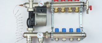
Manifold for underfloor heating with mixing unit and circulation pump
To ensure that all circuits receive water at the same temperature, it is supplied to a heated floor comb - a device with one input and a number of outputs. Such a comb collects cooled water from the circuits, from where it enters the boiler inlet (and partially goes to the mixing unit). This device - supply and return combs - is also called a manifold for heated floors. It can come with a mixing unit, or maybe just combs without any additional “load”.
How to adjust a warm water floor manually preparation and input
Manual adjustment is carried out using a conventional tap called a thermal head. It is mounted on the return and supply. Using a crane allows you to avoid loading the system with automation and additional equipment. This significantly reduces costs, but creates a number of inconveniences. High-quality and quick adjustment of a warm water floor with a thermal head is a myth. You will have to turn the tap often, and when determining the temperature, rely solely on personal sensations.
Important! It is considered more convenient to regulate water heated floors using rotameters (flow meters), which are installed at the entrance to each circuit (manifold installation location). All you need is to control the permissible difference in instrument readings
It is 0.3-0.5 l.
Correct adjustment of a heated floor with a thermal head requires compliance with the commissioning standards of the entire system. Otherwise, the system of main or auxiliary heating of air masses from below the room will malfunction.
How does the collector work?
Water floors are laid in various ways, for example, concrete or flooring, but regardless of the technology chosen, it is necessary to purchase and install a manifold cabinet.
In the future, two pipes will be inserted into it:
The cyclical nature of the process is ensured by another built-in component of the system - a circulation pump. One way or another, during the operation of a heated floor, say during repair work, the system has to be turned off. To do this, each of the pipes is equipped with shut-off valves. A plastic pipe and a metal shut-off valve are connected to each other through a compression fitting. Then a comb is connected to the valve, mounting an air vent on one end and a drain valve on the other. After assembling the cabinet, they proceed directly to installation. And only with a comb already installed on the wall can you cut the circuit pipes to length.
Setting up heated floors manually
In the case when the floor heating circuit operates without additional equipment and automation, the warm floor adjustment is carried out manually. The homeowner independently sets and controls the heating of the room to a comfortable level.
System preparation and commissioning
You can manually adjust heated floors thanks to a thermal head - a regular tap installed for water supply and return flow. In this case, the system will not be overloaded with additional devices and automation. For the owner, this is beneficial because it saves money on installing the circuit, but it creates difficulties in the operation of the crane.
It will be more convenient to use a flow meter (also known as a rotameter) installed at the inlets of the circuit near the collector. In this case, the adjustment comes down to monitoring the difference in readings of these devices - 0.3...0.5 liters. Manual adjustment assumes the correct first start-up of the floor heating system, during which all possible failures and malfunctions are identified.
The system startup process and its heating
It is necessary to put the underfloor heating system into operation not only after its installation, but also every year before the onset of cold weather. This process consists of several stages:
- Descent through air pipes;
- Filling the circuit with water;
- Adjusting heated floors and setting their operating mode for maximum performance.
Typically, owners install controllers, sensors and programmers on the circuit, the operation of which simplifies interaction with the system, but does not exclude the participation of the owner. The first launch is always done manually!
Setting up a heated floor step by step:
- Checking the valves on the manifold-distributor. All of them must be in the “closed” position;
- Check the filling of the heating system with water (coolants);
- Turn on the pump at minimum speed to heat the system;
- Open the return and water supply valves (“Open”);
- Check that the circuit is filled with coolant and air is discharged through the pipes through the vent (located in the manifold);
- Make sure that the circuit is filled with water and the air in the pipes is removed using a vent on the manifold;
The circuit fills gradually and slowly; the fewer revolutions the pump makes, the less likely it is that air pockets will occur in the pipes!
- Turn on the condensing heating boiler;
- Make sure that coolant is supplied to the circuit;
- Check the return;
- Perform a circuit performance test;
- Close the water supply and return valves;
- Carry out the procedure with each existing circuit.
Having filled all available circuits, the valves on the manifold are placed in the open position. The system does not immediately heat up to the set temperature, since it is quite inert to heat. The effect will be noticeable in 10 hours, maximum in a day. The duration of the response is related to the multi-layer arrangement of the floor heating system and the length of the circuit.
Warm floor and the space occupied by the manifold with flow meters
The peculiarity of a heated floor as a heating system is that the heated coolant, moving along the heating circuit, transfers part of the thermal energy to the floor surface. Thus, by heating the floor, heat is transferred to the air mass circulating inside the room in the direction from bottom to top. A number of devices control the supply of warm water to the heating circuits, the intensity and flow rate, including:
- three-way valve;
- circulation pump;
- collector.
The distribution of the coolant is controlled by a flow meter for heated floors. This device plays one of the key roles in the operation of the entire pumping and mixing group. Heated floor collectors are designed to supply hot water and collect waste coolant for its further use in the heating system pipeline. In the pumping and mixing unit, hot water coming from the heating source is mixed with the coolant returned to the circuit - return. The functionality and efficiency of heated floors is based on this operating principle.
Mixing unit with rotameters for a warm water floor system
Together with the operation of safety valves, rotameters are designed to regulate the temperature of the coolant in individual circuits of the water floor. Thanks to these devices, the required volume of prepared water entering the warm water floor system is ensured. In other words, this equipment monitors the amount of coolant in the water heating pipe, and therefore the functionality of the entire heating system.
Manifold and flow meter, equipment elements
A rotameter is a measuring device that shows the coolant consumption, how much of it passes through the connection point per unit of time.
A warm floor with a liquid system consists of the following components:
- circuit - tubes (loops, coils) through which warm water moves. It is not necessary, but it is desirable that the length of the coils and the methods of their installation be identical, which will simplify balancing;
- supply valves. This refers to the main taps that can completely shut off the flow from the source;
- pump. Hot water circulates thanks to it;
- a collector, or rather, a collector group with a flow meter. This part is the control unit, responsible for distributing the coolant along the circuits. It also has thermostats with valves and pressure gauges.
As you can see, the rotameter is installed precisely on the collector, and this is logical, taking into account the scheme we described above, since there mixing of water from the boiler and return occurs and its distribution occurs.
Temperature diagram example:
Typical connection diagrams
Water heated floors are rarely used as the only source of heating. Heating only due to underfloor heating is permissible only in regions with a mild climate, or in rooms with a large area, where heat removal is not limited by furniture, interior items or the low thermal conductivity of the floor covering. Almost always it is necessary to combine radiator circuits, hot water preparation devices and underfloor heating loops in one heating system.
Typical diagram of a combined heating system with connection of radiators and underfloor heating circuits. This is the most technologically advanced and easily customizable option, but it also requires significant initial investment. 1 - heating boiler; 2 — safety group, circulation pump, expansion tank; 3 - manifold for separate two-pipe connection of radiators in a star configuration; 4 — heating radiators; 5 - underfloor heating manifold, includes: bypass, three-way valve, thermostatic head, circulation pump, combs for connecting underfloor heating circuits with gearboxes and flow meters; 6 - heated floor contours
There are quite a large number of variations in the design of the boiler room piping, and each individual case has its own principles of operation of the hydraulic system. However, if you do not take into account very specific options, then there are only five ways to coordinate the operation of heating devices of various types:
- Parallel connection of the underfloor heating collector to the main line of the heating unit. The insertion point into the main line must be made up to the connection point of the radiator network; the coolant supply is provided by an additional circulation pump.
- Association according to the type of primary and secondary rings. The line, wrapped in a ring, has several supply connections in the supply part; the coolant flow in the connected circuits decreases with distance from the heating source. Flow balancing is performed by selecting the pump supply and limiting the flow with regulators.
- Connection to the extreme point of a coplanar manifold. The movement of the coolant in the heated floor loops is ensured by a common pump located in the generator part, while the system is balanced according to the principle of priority flow.
- Connection through a hydraulic separator is optimal when there are a large number of heating devices, a significant difference in flow rates in the circuits and a significant length of underfloor heating loops. This option also uses a coplanar manifold, but the hydraulic arrow is necessary to eliminate the pressure drop that interferes with the correct operation of the circulation pumps.
- Local parallel loop connection via unibox. This option is well suited for connecting a short-length heated floor loop, for example, if you need to heat the floor only in the bathroom.
The simplest option is to connect a heated floor circuit to a radiator heating system with a coolant temperature of 70-80 °C.
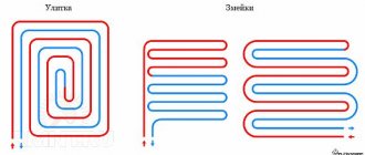
1 - line with supply and return of the high-temperature circuit; 2 - heated floor contour; 3 - unibox. It must be remembered that the nature of the operation of a heated floor may also change depending on the installation pattern of the coil. The “snail” scheme is considered optimal, in which the tubes are laid in pairs, which means that the entire area is heated almost evenly. If the warm floor is arranged as a “snake” or “labyrinth”, then the formation of colder and warmer zones is practically guaranteed. This drawback can be eliminated, including through proper configuration.
Temperature
Before you begin adjusting the heated floor, it is extremely important to establish a clear understanding of the purpose for which it is being done. According to the principle of operation, water-heated floors are fundamentally different from other heating devices.
The main difference is the operating temperature of the coolant. If the radiator network is supplied at temperatures up to 80 °C, then the heating of the coolant entering the heated floor coil is limited to 40–42 °C. This need is due to reasons of comfort and safety. In normal mode, the temperature on the floor surface fluctuates in the range of 22–26 °C; stronger heating causes unpleasant sensations.
There are two ways to regulate the heating temperature of a liquid heated floor. The first of them involves controlling the temperature on the supply branch of the collector by mixing in a portion of cooled coolant from the return. Technically, this solution is implemented by installing a three-way valve with a pressure-action RTL thermostatic head. The difference between such a head and a radiator head is that it relies on the temperature of the coolant, not the air. With this control method, the flow rate in the loops remains constant, only the coolant temperature changes with a small amplitude.
The second adjustment method involves limiting the flow of hot coolant in the circuit. In this case, a thermostatic head is also installed, but it is located on a two-way valve, which interrupts the return flow circuit. With this method of regulation, the supply and return are connected by a bypass circuit, the flow through which is regulated by a restriction valve with a pre-calibrated throughput. The principle of such regulation is based on the high inertia of the heated floor system. During operation, the coolant is supplied to the loops at the nominal temperature of the heating unit; only the total flow rate changes periodically. Thus, heating of the screed occurs cyclically, that is, a significant heat capacity of the accumulating layer is required to smooth out temperature changes.
In both cases, one important rule applies: the thermostatic fittings are necessarily based on the temperature of the return flow of the loop or collector. The device can have a mechanical or electronic principle of operation, it can even be a regular thermometer
The need for correct location is due to the fact that it is almost impossible to judge the effectiveness of the adjustment based on the temperature of the coolant at the supply, because the length of the loops can differ significantly.
Why do you need a flow meter?
Theoretically, it is quite possible to do without installing a flow meter in the manifold. However, if you do not install this device, then:
- Different rooms will have different temperatures;
- There may be excessive consumption of electricity to heat water in the system;
- Different circuits will heat up unevenly.
A simple example can be given: a bathroom and a bedroom. A gas or electric boiler heats water equally for both the bath and the bedroom. But the bathroom is at least 3 times smaller in area than the bedroom. Accordingly, the bathroom will be hot and the bedroom will be cool with the same water supply to the floor heating system. This situation is due to the fact that in the bedroom the total length of plastic pipes in the area is much greater. It is precisely in order to regulate a comfortable temperature in the entire apartment that it is desirable to install such a device.
Advice! When installing a water heated floor, you should strive to make the contours of the pipes approximately the same length. This will save energy costs and allow you to more accurately regulate the temperature.
Principle of operation
The device is installed on the return collector outlets. When the set temperature in the system is reached, the manifold valves narrow the lumen of the energy supply or close it completely. This principle of operation is possible with full automation of the system. For this purpose, the collector is equipped with a temperature sensor.
The flow meter itself consists of several parts:
The flask is usually made of durable glass; the body can be plastic or brass. The float is located inside the flask; it serves as an indicator of the coolant speed. The flow meter is also called a float rotameter.
In an automatic water heated floor collector, balancing of coolant flow is carried out using a temperature sensor. If the latter is not provided, then the rotameter can be adjusted manually.
Flow meter device
A rotameter is a mechanical device whose body is made of plastic or brass. It has a polypropylene float placed inside. The top of the case is equipped with a transparent bulb with a scale. This device is also called a float rotameter.
For your information! More often, a plastic rotameter is used in underfloor heating.
It is recommended to install a mixing unit with flow meters and a thermostat on the return line. This device is capable of supplying each loop with the required amount of coolant, and the outlet valves will open and close as the water cools.
It should be said that there are several types of water meters:
- measuring rotameter - mounted together with the valve, its regulation is carried out independently, taking into account the measured indicators;
- regulating - serves as a coolant distributor;
- combined - this type combines both models, but it also costs more.
Installation of a system with flow meters
The flow meter is installed on the return of the collector, as recommended by the manufacturers.
However, a feed installation option is possible. The main and important requirement for installing the device is to place it strictly vertically . This facilitates the correct calculation of the coolant level. The collector is placed in a horizontal position.
Automatic operation of the collector and rotameter requires the connection of a temperature sensor. This allows you to block the access of water to the loops when the desired heating degree is reached.
Flow meter installation:
- The device is screwed into the collector socket with a key in a strictly vertical position. The rotameter has an O-ring and a nut.
- Twist and remove the flask by turning it counterclockwise. Remove the ring and return the flask to its original position.
- Turn the brass ring clockwise, bringing it to the desired value, to find the balance of the speed of incoming water.
- Place a cover over the ring to protect it from damage.
At the end of the process, the system is checked for functionality.
How to install a flow meter correctly
According to the manufacturer's recommendation, the flow meter is mounted on the return of the collector, although installation on the supply is possible.
The main requirement when installing a rotameter is vertical placement. This position will allow you to correctly calculate the water level. Therefore, the comb must be positioned strictly horizontally. The installation accuracy can be determined using a plumb line or level.
Comb for heated floors: installation and configuration, making it yourself, step-by-step instructions with photos and videos.
Heated floor unit, balancing with flow meters.
Since the device - a collector plus a rotameter - must work automatically, an additional connection of a temperature sensor is required. This scheme completely or partially blocks the flow of coolant to the loops when the required heating degree is reached.
Do-it-yourself collector installation: connection diagram and configuration, types and principle of operation.
The flow meter installation process itself is as follows:
- The rotameter is installed - this is done by screwing it into the socket of the collector comb with a special key, the position is strictly vertical. The device is equipped with an O-ring and a nut.
For your information! This connection does not require additional insulation.
- The flask is twisted and removed by turning it counterclockwise. Then the ring intended by the manufacturer for protection is removed. After which, the flask with the marks is put on in the reverse order.
- The brass ring is turned clockwise to the required value, thereby balancing the speed of the incoming coolant.
- The brass ring is covered with a cover - this will prevent the device from mechanical damage.
After these steps, you must check the entire system for functionality.
Adjustment of the underfloor heating manifold with flow meters and its adjustment
After making sure that the structure is functioning, many people have a question: how to properly regulate a heated floor using flow meters? The process is simple, because the use of rotameters greatly simplifies the procedure.
With manual adjustment, the work is quite labor-intensive, since the adjustment is carried out using a conventional tap - a thermal head, which is installed on the return and supply.
This method significantly reduces the cost of installing the structure, but such adjustment will take a lot of time. In addition, the accuracy of the settings suffers during manual balancing, because you will have to determine the temperature based on your personal feelings.
The most convenient method is to carry out adjustment work using flow meters installed at the entrance to the coil. Separate adjustments should be made in each room, taking into account the level of fluid heating and hydraulic resistance.
All that will need to be done subsequently is to monitor the difference in indicators between the circuits; they should not exceed 0.3 - 0.5 liters.
Before setting up a warm floor on a collector using flow meters, you need to understand why this is necessary. The task of balancing is to establish the need for each branch and the overall balance of costs.
In addition, the correct setting of the flow meters on the manifold affects the quality of the floor covering during operation - after all, it should not overheat. Higher temperatures will damage the flooring product and require replacement.
The operating principle of underfloor heating differs from other heating devices. The peculiarity lies in the difference in water temperatures: if liquid circulates in radiators, heated to 80 degrees, then in a warm floor it is 40, while the surface warms up to 22 degrees.
For your information! There is an opinion that a warm floor system does not need balancing, and the water flow in the loops is regulated independently, using automatic devices - thermostats and controllers, but this is incorrect reasoning.
Regulatory process
As mentioned above, it is necessary to carry out separate adjustments for each circuit, taking into account the pipeline layout. After all, the volume of coolant required for each coil is different, and depends on its length.
This indicator is determined by the formula - the heat load is taken in relation to the heat capacity of water, and to the temperature difference at the inlet and outlet. Before the procedure, it is necessary to check the installed circuit for leaks, as they will distort the indicators during adjustment.
To do this, the pipeline should be filled with water and vented, that is, open the flow meters, three-way valve, air vent, and shut-off valves on the supply and return.
This procedure is accompanied by a whistling sound; when it stops, this indicates complete release of air. After which, all valves are closed except one on the supply side, and pressure testing of each circuit is carried out one by one.
Then, you can proceed to regulating the flow meters of the heated floor, the procedure is as follows:
- The size of the coolant passing through the collector group in 1 minute is calculated. This indicator is measured in liters, the resulting value is taken as 100%.
- The water demand for each water circuit is determined separately, as a percentage. The result should then be converted to liters per minute. You need to start with the longest loop, and at the highest power, by opening the control valve to full power.
For your information! Further, the flow rate in other coils will be set relative to it.
- The volume of water supplied to the main is adjusted using flow meters.
After the flow meters are configured, the circulation pump on the distribution unit is turned on. Hot water will begin to flow into the pipeline, which will displace cold water; this procedure will take 3 hours.
For your information! Before putting the floor into operation, the flow meters should be set to maximum values, usually they are different for each branch, and subsequently they need to be adjusted so that the heating is uniform.
It is worth saying that the process of adjusting a system with a rotameter depends on its model. If the flow meter does not have a built-in valve, then an additional shut-off element is required, which helps to set the “open” position. In this case, the balancing process occurs while the device is functioning.
If you have a combined type of device, it is recommended to carry out preliminary adjustment by turning the built-in valve to full power.
How to clean a flow meter
Inspection (repair) of the flow meter for warm water floors
The flow meter, like any device, needs periodic maintenance, or rather cleaning. The process is simple, and you can do the work yourself:
- The valve is closed by twisting the cap clockwise.
- The flask is removed and cleaned, after which it is put in place. Cleaning consists of wiping it from the inside with a soft cloth or rinsing it with water and detergent.
- Then the valve opens by rotating counterclockwise.
For your information! When dismantling the flask, there is no need to relieve pressure in the system, since the valves will not allow leakage.
It is not uncommon for the flow meter indicator to stick during operation of the collector group. To restore its function, you need to force open the shut-off valve.
If, during operation of the device, the flask cracks, then it is better to twist it and replace it with a new one, since the crack may interfere with determining the volume of coolant.
For efficient operation of a warm water floor, it is necessary not only to select the correct flow meter model, but also to carry out proper installation and configuration. If you are not confident in your abilities, then it is better to invite professionals.
Flowmeter functionality
A rotameter or, to give a full definition to this unit, a float rotameter, at first glance, is a common mechanical device. The design of the product is based on a plastic case (there are models made of brass), inside of which there is a polypropylene float. The body is equipped with a transparent bulb on which a marking scale is applied. The movement of the float up and down inside the device indicates a certain value on the scale, by which one can judge the volume of coolant circulating in the pipeline system - whether it is enough for the full operation of the heating circuits.
Traditional flow meter for underfloor heating manifold in various versions: on the left - in a plastic case, on the right - in brass.
From a theoretical point of view, the heating system can operate without this device. In this case, you will have to manually adjust the volume of water entering the circuit, based on your personal feelings when the air temperature in the room changes.
- individual circuits of the water floor will be supplied with coolant without taking into account the characteristics of the room, as a result of which the temperature values of the floor surface of heated rooms will differ;
- the energy consumption used to operate heating devices (electricity or gas) will be increased.
For example, you plan to heat the bathroom and children's room at the same time. An autonomous gas boiler will heat water for the bathroom and nursery in the same way, at the same temperature. However, the bathroom is smaller in area and will require less boiler water to heat it than to supply a heated floor in a nursery. You can achieve optimal supply of coolant to heated floors in each room using a flow meter. Consequently, due to the operation of this device, it will be possible to achieve individual temperature values for comfort in the bathroom and children's room.
Assessing the operation and principle of operation of the device, the following conclusions can be drawn:
- the device operates completely autonomously, without requiring additional power sources;
- the operating principle of the flow meter allows you to create optimal coolant flow for heating circuits, significantly reducing the energy consumption of heating devices;
- the design of the device provides visual control over the amount of water in the pipelines;
- the collector together with flow meters for underfloor heating significantly facilitates control over the operation of the entire system, is easy to install and unpretentious to maintain.
How does the water meter of a heating floor collector work?
Let's describe how the flow meter works. The functionality of the device is ensured by its valve part; it is equipped with control rings or a valve. When these controls are moved, the lumen of the pipe narrows, accordingly, the flow weakens/increases, the temperature on the circuit changes, and at the same time the float inside the transparent flask moves, showing the set value. In this way, the thermal power of coils with different hydrodynamic resistance is balanced. There are models with a valve installed separately; the operating principle is similar, the elements are simply separated.
So, in a float rotameter, namely such devices are used for floor water heating systems, there is a plastic transparent flask with a float indicator indicating the intensity of circulation. The liquid constantly flows inside, drowns the specified element (it can be called “eternally floating”), which the spring tries to return to its place; the more powerful the flow, the more it sinks.
Criterias of choice
The quality of functioning of the underfloor heating system depends on the correct selection of the flow meter. Three types of rotameters are produced:
- Measuring. This type of flow meter is installed with a manual adjustment valve. Control is carried out taking into account measurement readings.
- Regulating. It performs only one function - controlling the amount of coolant entering the water circuits.
- Combined. Such a device combines two actions - adjustment and measurement. The cost of the product is significantly higher than that of models performing the same type of functions.
When purchasing a flow meter for heated floors, you should pay attention to the following product parameters:
- Case material. Devices made of brass have high wear resistance. The top of such a body should be covered with nickel. Plastic products are cheaper, but they have a reduced strength rating.
- Device integrity. Before purchasing a rotameter, it is recommended to carefully inspect the housing and transparent bulb to exclude the presence of cracks or other defects.
- Inner part. The spring in the middle of the flowmeter body should be made of stainless steel.
- Flask. The transparent cap with a measuring scale in high-quality models is made of polycarbonate. This material is quite strong and has high heat resistance, which is especially important when used in heating systems.
- Specifications. The instructions supplied with the device indicate the temperature level. This indicator should be no lower than 110 degrees. Also equally important is the pressure - at least 10 bar.
- Maximum throughput value. The rotameter must be able to conduct at least 2-4 meters of coolant through itself in an hour.
Flow meter for heated floors
You should also pay attention to the manufacturer of the product. The main indicator of the reliability of a product is the availability of a quality certificate and the provision of a guarantee, which responsible companies offer for up to five years.
The influence of the coolant supply method on the choice of control technology
Control of heating of water heated floors equipped with their own heat pumps occurs under conditions of continuous supply of coolant at high speed and in large volumes. Such systems use the admixture of cooled liquid to the supply stream to bring its energy parameters to the specified ones. The mixing is carried out in pumping and mixing units (PMU), which lower the temperature of the coolant from the primary high-temperature heating circuit to the design ones. Further adjustment of the temperature of the heated floor is carried out on the combs and has already been described above. NSU blocks provide optimal operating conditions for underfloor heating, and also allow it to be installed in unlimited areas.
However, with a small TP quadrature it is possible to avoid the use of expensive mixing units. The temperature of the coolant for the heated floor, in this case, is maintained by the method of limiting flows or by the RTL scheme. The functional principle of the circuit is the portion supply of coolant into the circuits. In each branch, the active element of the thermostatic valve, installed on the return line, having warmed up to the set temperature maximum, blocks the flow of working fluid. The heat gradually released by the coolant is dissipated in the concrete screed. After the system has cooled to the minimum temperature threshold, the valve opens and the batch feed cycle is repeated.
The simplicity of RTL control of underfloor heating makes it especially attractive. After all, it is enough to use a set of thermomechanical valves installed on the comb, or compact “unibox” type assemblies. However, when choosing an RTL scheme, you should not forget about its limitations:
- it is applicable only in heated floors made under a thick concrete screed, which plays the role of a heat accumulator;
- For efficient operation, in addition to good heat removal, the circuit pipelines must have minimal hydraulic resistance. This is necessary to quickly update the coolant. Taking into account the absence of a heat pump in the TP system, such conditions are met if the length of the branches does not exceed 50 m with a pipeline diameter of 16 mm. If it is necessary to slightly increase the length of the circuits, it is recommended to use pipes Ø 20 mm.
Important! The use of pipes of different diameters in one system (on one collector) of underfloor heating with RTL control is strongly not recommended.
Installation and configuration of a heated floor collector - how to do it
Where to place the collector
It is recommended to place the collector above the level of all connected circuits. Automatic air vents should be located on the combs, and be at the highest point of the entire floor heating system. If you don’t want the floors to not work and become airy, you need to maintain the level.
The distance from the finished floor to the connection point of the pipes on the combs should be such that no obstacles are created for the convenient connection of pipelines coming out of the screed.
More often, collectors are assembled by the manufacturer for connection “on the left”. If it is necessary to connect “on the right”, the product components are rearranged in accordance with the instructions.
It may also be necessary to rotate the pump 90 degrees in order to reduce the overall size of the product. This is usually not difficult to follow the instructions.
Consolidation
The easiest way to fix the collector is to use a special cabinet, built-in or wall-mounted.
Use standard mounting schemes provided by the manufacturer. Use a special cabinet or racks, shields with vibration dampers.
Equipment, collector design
Let's look at the installation of a collector using the example of a product from one of the manufacturers.
This collector is assembled according to a common scheme and includes standard components.
- 1. Circulation pump.
After fixing the collector, underfloor heating loops and supply pipelines are connected to it, while all valves and taps must be closed.
Coolant in the system
An important issue is preventing oxygen from entering the system. It is necessary to use materials, parts, and units with minimal permeability to oxygen.
How to fill a heated floor system
The underfloor heating system is filled with coolant through the drain valves on the manifold. The connected loops are filled one by one.
To do this, the control valves (thermostatic and balancing) of only one circuit are opened alternately, while all other valves on the manifold must be closed.
- Bypass valves 5, thermostatic valve 3, trim valves 2 and 4 are closed.
It is recommended to carry out hydraulic tests of the entire underfloor heating system. To do this, the pressure in the manifold and circuits rises to at least 1.43 from the working pressure, but not below 3 atm, for at least 2 hours.
Setting the flow rate in the collector based on coolant temperature
Commissioning and initial setup of the underfloor heating collector are as follows:
- Valve 2 is completely open.
3 completely open.
4 completely closed.
Pump 1 is on.
During the first few days (as well as during operation), it is possible to further configure the system with valve 4 according to the situation and preferences.
Installation and adjustment of the pump
Depending on the required performance, a 15-40 pump can be installed for 2 - 6 collectors or a 15-60 pump for 7 - 10 collectors.
Both pumps without electronic control, such as UPS, and modern ones with electronic control, such as ALPHA2L, can be used.
In the first case, the settings are limited to the “Fixed speed” modes. Depending on the heated area, it is possible to use 1, 2 or 3 speeds, and the temperature difference between supply and return should be within 5 - 10 degrees.
How to balance underfloor heating circuits
The collector is balanced (initial setting) using balancing valves. It is necessary to equalize the pressure drop between the circuits and supply the required amount of coolant to each circuit.
- Use a 5 mm hex key to remove the cover (A).
To install the servo drive on the thermostatic control valve, remove the manual control handle (A), install the adapter ring (B) on the valve, insert the servo drive into the grooves of the adapter ring, and turn the adjusting ring clockwise until it clicks.
Disadvantages of heated floors without a rotameter
The flow meter for the underfloor heating manifold regulates t° indirectly - through normalizing the fluid flows on the coils. Depending on the dimensions of the branch, a different amount of coolant is required, which cools down during movement precisely according to calculations.
If one small room is heated, then setting up the flow meters and they themselves may not be required. You can do without the device, and adjustments can be made by simply closing the supply tap or adjusting the pump. But if there is an object with several circuits, such manual adjustment will be extremely inconvenient; it will not be able to ensure that the values are set separately for each coil; in addition, it will be impossible to track consumption. With a water meter, balancing can be done by simply turning its adjusting nut, and the consumption level will immediately be visible on the transparent bulb.
Disadvantages if the underfloor heating collector does not have a rotameter:
- the temperature in rooms of different geometry, degree of thermal insulation, and length of contours will not meet their needs. For example, heating will be intense even where it is not needed;
- excess energy consumption will occur. The equipment will need to be used for a longer period, since uneven heating will lead to incorrect, and in certain areas, slower heat distribution.
It is a mistake to assume that optimal flow for several circuits can be achieved by adjusting the performance of the circulation pump and not equipping the floor with flow meters, since it is difficult to accurately calculate the length of the tubes. Such a calculation will lead to the fact that the amount of resource on the coils will differ from the calculated indicator. And also this violates the principle of choosing equipment: it is necessary to start from the needs of the user, and not from the parameters of the device.
Features of adjustment
For each individual room, the rotameters are adjusted separately. Control is carried out according to the diagram of the installed circuits
In this case, the level of heating of the liquid and pressure is taken into account
It is recommended to carry out balancing according to the following instructions:
- The total amount of coolant passing through the collector in one minute is determined. Indicators are taken in liters. The resulting value is taken as 100 percent.
- The percentage flow rate of each individual water circuit is calculated. The result is converted to liters per minute.
- The flow meter regulates the amount of liquid supplied to the pipeline.
Using these steps, you can perform long-term adjustments to the water circuit. To indicate the actual parameters, it is necessary to observe the flow meter readings. According to observations, it is possible to accurately determine the flow rate of the circuits connected to the collector.
Manifold with flow meters for heated floors
The flow meter is adjusted depending on the installed model. After connecting the device to the manifold, preliminary settings should be made by setting the initial position, which allows access to liquid.
In rotameters without a built-in valve, an additional locking device is used to set the “open” position. In this case, balancing is performed during the operation of the system.
Combination devices for metering coolant flow can be pre-set using full turns of the built-in valve. Each turn allows you to reduce the clearance by a set value.
Adjustment of the flow meter of the floor heating system is carried out taking into account the control of the fluid speed in one minute - from 0.5 to 5 liters.
Before setting up the rotameter, you should check the condition of the installed circuit. Trial testing is necessary to exclude the presence of leaks in the circuit, which could cause distortion of the indicators in the device.
The flow meter is an important element in a multi-circuit underfloor heating system. The device allows for a uniform flow of liquid into all individual pipelines. In order for heating equipment to function as efficiently as possible, you must select the right rotameter, as well as install and configure it in accordance with technical requirements.
Finally, the heating system of my house is assembled. The boiler is started. Let me remind you that I decided to heat my house only with heated floors. Although there are not many rooms in the house, in order for the comfort in all rooms to be the same, it is necessary to adjust the heated floor. We will talk about how to set up a heated floor in this article.
Setting up a heated floor is not as complicated as it might seem at first glance. Generally speaking, setting up a heated floor consists of three stages. First, balancing the underfloor heating loops, then setting up the pump and mixing unit, and finally setting up the controller if you decide to automate the heating system. I decided to fully automate the heating system in my house. Therefore, I purchased a controller, servos and temperature sensors. Let's look at the first stage of setup in detail, since the success of the entire setup depends on how well it is done.
Adjusting the rotameter in stages
It is appropriate to call the procedure balancing a heated floor, since the boiler has limited capabilities and the goal is to create the most effective balance in the distribution of its resource between the heating circuits.
The idea is simple: each rotameter shuts off the flow of water according to the principle of a regular tap; the lower the flow it creates, blocking the liquid inlet to the circuit with its valve, the lower the temperature, and vice versa. The essence of the adjustment is elementary - limiting the pressure and volume of incoming coolant.
Adjustment of heated floor flow meters, the procedure for installing them on the heated water floor manifold is almost always prescribed in the product instructions.
Let's look at installation and how to adjust (balance) for a common standard size float flow meter with two washers-rings for adjustment at the bottom of the body:
- Insert the rotameter into the seat on the manifold comb.
- Remove the protective sleeve and safety pin or similar device, usually in the form of a ring. Different models almost always have the first one, but may not have the second one;
- Screw in the product, tightening it with a wrench with a small reasonable amount of force. This procedure can also be performed without a tool, by hand, since it does not require particularly strong tightening, the main thing is that the device sits tightly in the socket. There are also sizes with a locking union nut;
- Turn counterclockwise. the upper adjustment ring, the valve will open completely. With this manipulation, the device is brought into readiness, into its original state. The flow indicator will move to o.
- Start the system.
- Next, the same upper ring is used to set the desired value, determined according to the user’s calculations.
- To ensure that the set parameter does not go astray, fix it by turning the bottom washer until it stops.
- Upon completion of the procedure, do not forget to cover the adjustment unit with the same protective sleeve. This will prevent mechanical damage and shifts from accidental influences.
- The last stage is to check how the configured equipment is heated, to observe for some time the intensity and speed of reaching the desired temperature.
It is necessary to adjust it smoothly, since reducing the flow on one device increases its intensity on other circuits. The adjustment, that is, the set pressure, will be indicated by the pointer position opposite the scale gradations.
For models of rotameters without an integrated valve with a segment with a speed scale, such a valve must be installed separately. When balancing a heated floor with flow meters of this type, these valves are switched to a fully open state, and then the system is started and adjustment is performed by adjusting them. That is, at its core the process is similar to the one described.
Methods for adjusting the temperature of heating floors
To achieve the required temperature values that meet standard standards, you need to configure the device.
Correct adjustment of heated water floors is possible taking into account the type of room. The suitable temperature level for residential premises is from 20 to 28 degrees. For a kitchen, hallway or bathroom, heating from 19 to 24 degrees is suitable.
For your information! The permissible air humidity in the room is 60%, but 40 - 50% is considered optimal.
The main purpose of regulation is to ensure a constant temperature difference between the inlet and outlet. To determine the temperature difference, the thickness and material of the screed and the laying pitch of the pipes are taken into account.
The methods of adjusting the structure are influenced by the installed equipment; it can be mechanical or automatic. The device responsible for water flow is adjusted; this can be done by mixing hot and cooled coolant, or by limiting it.
Automatic adjustment
If underfloor heating is adjusted automatically, then the main adjustment elements are the RTL thermal head or the unibox valve. The level of heating of the floor depends on the set indicator; the higher it is, the hotter the liquid running through the pipes will be, and therefore the floor covering will warm up more strongly.
How to automatically adjust a water heated floor - this can be done in two ways:
- Using a thermostatic self-regulating device, adjustment is made using valves or a tap with heads.
- Using an electronic system, it includes an electric thermometer, a controller, and electric drives.
Electronic control devices are expensive, but with their help you can program floor heating and set it up for optimal and efficient operation.
Electronic regulators are represented on the market by many companies, the most popular being Onor products.
Manual temperature equalization
The manual setup process is simple but time-consuming. The water heating temperature is adjusted by opening or closing the valves. The procedure becomes much simpler if you have a device that meters the supply to each branch.
For your information! Heating floors will function effectively with manual settings - with intensive water circulation in the pipeline, this can be achieved using a separate heat pump.
Before you start adjusting the temperature level in the water floor, you need to make sure that the system is full and there are no air pockets. Setting is the supply of coolant to each coil and setting its flow rate. Control is carried out taking into account the difference in flow temperature at inlet and outlet. This procedure must be carried out annually.
Important! The temperature of the incoming coolant and the exhaust coolant in all loops should be approximately the same, the permissible difference is 5 - 15 degrees.
Monitoring the adjustment process of the water floor will make it easier to use a thermometer, laser or electric. Its presence will significantly reduce setup time.
Manual adjustment of TP collectors
The simplest, although time-consuming, setting method is to adjust the temperature of the heated floor using manual valves.
The task is somewhat simplified by installing flow meters (rotameters) on the comb. Flow meters simplify the dosage of the amount of circulating coolant (flow) in one separate circuit of the underfloor heating system. In the case of group temperature control throughout the collector, the rotameter can also be used to balance the flow of coolant (smoothing out the difference in hydraulic resistance) along loops of different lengths.
The main elements of a flow meter valve are:
- housing with shut-off and control valve. It is screwed into the corresponding technical hole of the manifold;
- a flask made of transparent plastic or glass with a printed scale;
- float indicator that allows you to visually control the flow of liquid through the rotameter.
Manual adjustment of the underfloor heating manifold is carried out by screwing/unscrewing manual valves or adjusting the throughput of flow meters.
The sequence of manually setting the temperature of a warm water floor
At the beginning of the adjustment operations, it is necessary to make sure that the pipelines of the TP system (secondary circuit) are completely filled with coolant and have no air pockets. They are filled following the main heating system (primary circuit). At this time, all shut-off and control valves on the collectors must be closed.
After opening the main valves for the supply and return of the distributors for heated floors, the shut-off devices on each of the loops are opened sequentially. Air is bled through Mayevsky valves or automatic comb air vents. It is recommended to fill the next branch only after the previous one has been completely filled and its air has been guaranteed.
Having completed filling the first loop, it is necessary to turn on the heat pump of the secondary heating circuit and circulate the coolant through its system. The efficiency of liquid circulation is checked with built-in or overhead thermometers. As a last resort, you can simply put your hands on the supply and return pipes at the same time - they should be warm, but with a slight difference in heating.
The filled first loop should be cut off from the collectors at both ends using local shut-off and control valves. Then, the above actions are carried out with the next loop.
After sequential filling of all heat pump circuits, their shut-off devices are opened and the heat pump is switched on to operating mode. The temperature of the warm water floor is adjusted through the supply of coolant to each of its branches. It is set by changing the liquid flow rate (with a valve or rotameter), and control is carried out by changing the temperature gradient between the supply and return flow. Ultimately, this difference for different circuits should be the same, within 5-15C. The longer the loop, the more intense the coolant will cool and the greater its consumption required.
To monitor the correct adjustment of a warm water floor, it is rational to use non-contact laser or contact electric thermometers. Their installation to measure the temperature of the supply and return pipes will help reduce the time to obtain the result of changing settings from several hours to 10-15 minutes.
Optimal temperature parameters
Setting up a water heated floor is carried out depending on individual needs. Some people like it when the room is warm, while others prefer invigorating freshness, even in the most severe frosts. But despite this, there are general standards that were developed taking into account sanitary standards, these include:
- floor heating up to 28 degrees;
- if there is another heat source or if you live indoors permanently, the ideal level is from 22 to 26 - these are optimal conditions for a person;
- if this type of heat source is the only one, or it is located in the bathroom, corridor, balcony, or in a house where people do not live permanently, it is permissible to raise the degree to 32.
Therefore, when regulating water floors, in addition to your preferences, so that the microclimate in the apartment is healthy, you should take these standards into account.
Kinds
The design of different models of combined type measuring and adjusting float water meters is almost the same:
Types of water meters based on functionality for underfloor heating manifolds:
- measuring - a shut-off valve must be installed to it, the valve of which is turned by the user to adjust it, depending on the values shown by the water meter;
- regulating - only for coolant distribution;
- combined - two types are combined, with a built-in valve. Some models can perform automatic adjustment.
For underfloor heating, the first and second types of float rotameters are most often used.
High quality flow meter
In the store you may encounter a wide selection of different rotameters, so in order to choose a high-quality copy, you can select it according to the following characteristics:
- The flowmeter must have a high-quality housing without chips or protrusions. The body material is brass, but the top is coated with nickel.
- The internal spring of the rotameter must be made of stainless steel.
- Polycarbonate is an example of an ideal material for a transparent flowmeter bulb, because this material can withstand high temperatures, as well as some physical influences.
- It is impossible to determine this in a store, so you will have to trust the manufacturer and pay attention to the indicators: the device must withstand temperatures up to 110°C, as well as a pressure of 10 bar.
- The maximum throughput of the rotameter should not be lower than 2-4 cubic meters per hour. The measuring scale must correspond to these readings.
- The warranty for these products is long, often from 5 years.
Conclusion
A manifold for a warm water floor with flow meters allows you to control the flow of coolant, which ensures a comfortable floor temperature in any room connected to this circuit. This method of organizing a heated floor system additionally saves money, because you spend less energy on heating water.
Sources
- https://TeploRes.ru/ustrojstva-i-pribory/rashodomer-teplonositelya-2.html
- https://MasterpoToku.ru/full/kak-podklucit-kollektor-teplogo-pola-7-osibok-i-avtomaticeskoe-regulirovka-temperatury.html
- https://ZnatokTepla.ru/teplyj-pol/kollektor-s-rashodomerami-dlya-teplogo-pola.html
- https://mr-build.ru/newteplo/regulirovka-teplogo-pola.html
- https://lucheeotoplenie.ru/teplyj-pol/regulirovka-kollektora-teplogo-pola.html
- https://okcomfort.com/pol/pol-s-podogrevom/vodyanoj-teplyj-pol/kak-nastroit.html
- https://mr-build.ru/newteplo/rashodomer-dla-teplogo-pola.html
- https://OmShantiDom.ru/teplyj-pol/vodyanoj-teplyj-regulirovka-temperatury.html
- https://polspec.com/teplyy-pol/kak-vybrat-i-ustanovit-raskhodomer-dlya-teplogo-pola.html
What do you think of this article?
How to choose
A manifold for underfloor heating is often sold ready for assembly; the kit may not include rotameters, but usually recommended flow meters are always specified in the technical documentation for each version of such a product.
Some tips on how to choose the right rotameter:
- The more elements of the device are made of metal (brass), the better. This product is more wear-resistant. But also, if you need to save money, plastic products are often used: the environment of use does not create too much stress, so a device with a plastic stand will work for a long time;
- When purchasing, it is important to inspect the product to ensure its integrity (especially the flask);
- the spring inside must be steel. The material is indicated in the instructions; if this item is not present, it is likely that the manufacturer produces unreliable products;
- polycarbonate bulb of quality products;
- recommended minimum parameters (specified in the instructions): the product must be designed for +110° C and above, pressure - from 10 bar;
- throughput from 2–4 m³;
- Availability of a certificate, warranty - from 5 years.
Of course, if there are many circuits, it is advisable to buy a water meter for each, since a change in the flow on one branch changes it on all the others, this will allow for more rational use of the boiler’s capabilities. The comb will be a kind of control unit with protruding rotameters, with different positions of indicator floats inside the flasks.
Connection methods
You will need the following materials and devices:
- Pipeline;
- Pipeline components;
- Boiler;
- Three-way thermostatic valve;
- Pump assembly.
Some people try to use the simplest installation method - to embed the underfloor heating system directly into the central heating system. However, this approach threatens serious damage to the pipeline, because The temperature for radiators is much higher than that needed for the floor. Also, if such a “homemade device” is discovered by supervisory authorities, the owner of the apartment faces serious penalties and an order to completely dismantle the warm water floor.
Options for laying a pipeline without a collector: snail and snake. Moreover, both schemes must consist of a double pipeline: 2 parallel loops to the heated floor - supply and return.
- The advantage of the “snake” is that you can distribute heating zones. For example, go around furniture or plumbing fixtures.
- The advantage of the “snail” is more uniform heating of the entire area.
After laying the pipeline, it must be connected to the boiler. You must first calculate the pump power. The following formula is used:
G =Q X 0.86/Δt,
where G is the system capacity (l/h),
Q - system power (W),
0.86 — conversion factor in Kcal/h,
Δt—flow-return temperature difference (°C).
A pump is needed to ensure the speed of coolant movement through the pipes. Depending on the type of pump, it can be controlled either manually or automatically. The device is mounted on the supply pipeline. In a system without a mixing unit, the pump device is located under the boiler. The circuit between the pipeline with the pump and the boiler is closed by a three-way thermostatic valve.
In order for the heated floor to work stably without installing a mixing unit, you should choose a high-quality, powerful boiler. Electric or gas – it doesn’t really matter. The main thing is that the power of the device is designed specifically for the designed heated floor. Experts recommend choosing models with a pump.
Heating circuit control
With high-quality temperature control of the coolant, its flow rate remains unchanged unless additional automation equipment is installed. Without them, the volume of water passing through the circuit is adjusted only manually - by valves and rotameters located on the supply/return manifold. But thermal valves can also be controlled automatically if you install servos on them.
Servo drives are attached to thermostatic valves on the return manifold and control them at the command of the controller
The system works like this: in the rooms there are wired or wireless thermostats that monitor the air temperature and are connected to a single control unit (controller). Receiving signals from room thermostats, it opens and closes the valves on the heated floor comb using servo drives. In this way, the controller can control underfloor heating and the radiator system simultaneously, as shown in the diagram:
In addition to temperature regulation together with thermostats, the controller can do a number of interesting things:
- respond to changes in weather conditions outside;
- preheat the required premises by a given time;
- turn off underfloor heating in unused rooms;
- controlled remotely via GSM connection or the Internet.
The use of servo drives and automation equipment not only increases the comfort for residents, but also allows you to save 15-20% of the money spent on energy costs and thus reduce the cost of heating a private home.
Equipment and capabilities
Products are manufactured under the Valtec brand by an Italian company. They have been on the Russian market since 2003, so they know our realities first-hand. We produce a wide range of plumbing engineering fixtures and devices. And collectors for heated floors are among them.
general description
The Valtec underfloor heating manifold is made of brass or stainless steel. Or rather, most often, the body is made of stainless steel, and the “filling” is made of brass. In the catalog they are called a manifold block, since there are a couple of devices - for the supply and for the return pipeline. Complete kits are equipped with:
- there are flow meters on the feed comb;
- on the return pipeline there are manual shut-off valves.
Below is the supply and there are flow meters. At the top is the return pipeline, manual valves are installed
In this option, using flow meters, you can adjust the coolant flow in each of the loops, and manual valves on the return pipeline serve to block circulation. But this configuration can be automated. To do this, servo drives are installed on manual valves, which are connected to thermostats installed in the premises. In this way, a constant floor or air temperature can be maintained. Depends on where the heat sensors are installed, because the thermostat reacts to their readings.
An automatic air bleeder is also installed on the Valtec manifold. This is a device that allows you to remove air trapped in the coolant automatically.
Range
All collector blocks for Valtek underfloor heating can be divided into two groups: with and without adjusting flow meters. There are only three options in the first group and two in the second, but in each the number of connected taps is from two to twelve.
- With flow meters on supply
- VTc.594.EMNX. Body - stainless steel AISI 304, fittings - brass CW617N, seals - EPDM 70Sh, number of outlets - from 2 to 12. Operating pressure 8 bar, nominal diameter of manifolds - 1 inch, outlets - 3/4″ external thread, connection - eurocone. Price - from 9 thousand rubles. (for 2 outputs), up to 25 thousand (for 12 outputs).
- VTc.589.EMNX. Manifold for propylene glycol systems. Body - AISI 304 stainless steel, brass fittings and EPDM 70Sh rubber seals. Working pressure 9 Bar, coolant temperature not higher than 90°C. The nominal diameter of the collectors is one inch, the outlets are 3/4 inch with a Eurocone.
How to save money on a mixing unit
Many master plumbers consider it an integral part of the underfloor heating manifold, although these are 2 different elements that perform separate functions. The task of the comb is to distribute the coolant along the circuits, and the mixing unit is to limit its temperature to 35-45 °C, maximum 55 °C. The collector connection diagram shown below works according to the following algorithm:
- While the system is warming up, the two-way valve on the supply side is completely open and allows maximum water through.
- When the temperature rises to the calculated value (usually 45 °C), the remote sensor acts on the thermal head, and it begins to block the flow through the valve, pressing on the rod.
- After the valve mechanism is completely closed, the coolant, stimulated to move by the pump, circulates only in a closed floor heating network.
- The gradual cooling of the water is detected by a temperature sensor, causing the thermal head to release the rod, the valve opens and a portion of hot water enters the system, while some of the cold water goes back. The heating cycle repeats.
Good news for those who are very limited in funds, but want to heat themselves with warm floors: installing a two- or three-way valve with a pump is not always necessary. There are two ways to reduce the cost of the system by avoiding the purchase of a mixer:
- power the heating circuits directly from the gas boiler through the manifold;
- install RTL thermal heads on the manifold valves.
The manifold assembly, assembled from brass tees, provides for regulation by automatically limiting the reverse flow with RTL heads.
Let us immediately note that the first option contradicts all the canons and cannot be considered correct, although it is used quite successfully. The bottom line is this: high-tech wall-mounted gas boilers can maintain the temperature of the supplied water at 40-50 °C, which is acceptable for heated floors. But there are 3 negative points:
- In spring and autumn, when there is minimal frost outside, the boiler will not be able to lower the coolant temperature below 35 ° C, causing the rooms to become stuffy and hot due to heating of the entire floor surface.
- In the minimum combustion mode, the parts of the heating unit are covered with soot twice as quickly.
- Due to the same mode, the efficiency of the heat generator is reduced by 5-10%.
Thermostatic heads of the RTL type operate on the principle of a two-way valve, only they are located on each circuit and are not equipped with remote sensors. A thermoelement that responds to changes in water temperature is located inside the head and blocks the flow along the circuit when it has heated up above 45-55 ° C (depending on the adjustment). In this case, the comb is connected directly to a heat source running on any type of fuel - wood, diesel or pellets.
Important condition. For normal operation of heated floors controlled by RTL thermal heads, the length of each circuit should not exceed 60 m
More details about the design of such heating and the correct schemes for assembling the collector are described in a separate instruction and in the next video:
Setting up manifolds with tuning flow meters
Preliminary adjustment of underfloor heating collectors is necessary and important. Even if the system has thermostats, controllers and other automation. If you entrust the adjustment to automation, after a while all flows will be as open as possible. So before starting the system, we are setting up the collector. Adjust the flow rate on a cold system without turning on the boiler. Heating is started after setting the flow rates in the loops - to check the temperature.
Valtec manifold with flow meters is easier to configure
What is a flow meter and its design
Flow meters are used for the initial setting of flows, which is easier, more accurate and faster. In addition, during operation they allow you to evaluate the current flow rate in relation to the one set during setup. To understand the mechanics of adjustment, you need to know how the flow meter is designed and how it works. It is a hollow body with a poppet valve, which is supported by a spring. The spring is calibrated. Its top is formed into a transparent cone with a scale.
How does the Valtek flow meter work?
In order to be able to navigate by the flow values and, in fact, regulate it, a flow indicator is attached to the spring. For supply-mounted flowmeters, the default flow indicator is mounted on the top of the housing. In this position, it points to “0” and the flow is blocked (as in the photo above). If flowmeters are designed for installation on a return manifold, the flow indicator is located at the bottom.
There are two types of flow meters - with and without fixing the position of the adjusting sleeve. The first ones are more reliable, since the settings are not lost, which can happen with regular ones. But they are more expensive. And since the collector unit itself is not cheap, flow meters are often installed without fixation.
How to set the flow on a flow meter
The scale has marks and numbers from 0 to 5. The number indicates the strength of the flow - this is the speed of movement of the coolant in meters per second (m/s). The flow adjustment procedure is as follows:
Aligning the flow meter with a fixing ring
Connecting underfloor heating pipes to the comb
Installation of heating pipes begins with connecting the free end of the tube to the fitting of the supply comb of the distribution manifold.
Most modern manufacturers, such as Rehau, do this using a threaded connection for a Eurocone. It is considered one of the simplest and most reliable in execution today.
Eurocone often comes with a diameter of 17mm, while a lot of users assemble their underfloor heating system from a 16mm pipe. In this case, you will have to calibrate the tube to the specified size.
You can use original cross-linked polyethylene tubes from Rehau, which are 17-gauge, then everything should work without additional movements.
Error No. 1 - it is not recommended to process and expand the end of the tube with an unsuitable tool.
Someone expands the wall using metal scissors. Everything seems to fit, but you won’t achieve perfectly even contact this way.
The reliability of the connection will ultimately suffer from this. With frequent temperature changes, it is quite possible for a leak to appear in this place in the future.
Next, put a union nut on the tube, insert a ferrule ring and a thrust bushing there.
Then hand-tighten the end of the tube to the connecting fitting.
In order not to tear off the fitting on the manifold, final tightening should be done using two wrenches. Use one to fix the hexagon on the fitting, and use the other to tighten the threaded connection.
When installing elastic pipes, it is better to enclose the collector line near the floor in a rotation lock.
At the entrance to the screed, the pipes must be covered with a protective casing made of corrugated pipe or thermal insulation. The recommended length is at least 0.5 m.
25cm will go out, and the other 25cm will be located in the screed itself.
Mistake No. 2 - if you do not put on a protective casing, the tube will be damaged by the sharp edges of the screed as it expands in temperature.
The heating circuits should be laid in increments of 100mm.
Installation of the circuit ends by connecting the other end of the pipe to the corresponding fitting of the return comb.
In the area where pipes are connected to the manifold, where the distance between the pipes is minimal or they run close to each other, they also need to be placed in thermal insulation or corrugation.
This will prevent overheating of the screed and will reduce the surface temperature near the collector itself. In exactly the same way, connect all the other circuits one by one.
Mistake #3: Don’t confuse supply with return. It is not always where the flow meters are located that the supply hoses are connected, and the return hoses are connected to another comb.
It all depends on the type of rotameter. Therefore, check the documentation. In one case, the rod must be deflected downward by the flow of water, so the supply is introduced through it.
And in the other, on the contrary, raise the rod up.
You can distinguish them by the scale. For those that serve, zero will be at the very top, and the scale will correspondingly increase towards the bottom.
Those on the return line have a zero at the bottom, and the numbers increase upward.
Step-by-step instructions for installation and adjustment
The rotameter is installed strictly vertically. To ensure that the liquid level in the flask is accurate, the collector itself is also mounted according to the level. If the comb pipe is installed crookedly, the temperature adjustment will be incorrect.
Since finishing work often occurs after installation of the collector, it is necessary to protect the assembly and its components from possible damage. The best option is to make a niche or a special cabinet for it in the wall.
Installation and adjustment:
- Using a wrench, screw the flow meter into the process inlet of the return line of the manifold;
- Turn the membrane (flask) counterclockwise to open the pressure meter;
- Remove the factory protective ring;
- Turn the brass housing ring clockwise to the desired pressure level. This is balancing the energy flow rate. The float on the scale will indicate the set value;
- Cover the brass ring with a cover plate. This must be done to avoid damage to the device, especially if the water heated floor unit is not closed in a niche or cabinet;
- Check the system operation.
During operation of the unit, the flask remains open so that the level of the water float is visible. If balancing is needed during operation, the membrane is simply turned in the desired direction.
Connection rules
In most cases, a ready-made manifold is purchased, in which all elements are selected according to technical characteristics. If you have experience in assembling such structures, you can assemble the device yourself. How to properly connect a heated floor, take into account the parameters of the overall heating system and the technical properties of the combs? To do this, you must follow certain installation rules.
Attention
First, a general connection diagram is drawn up, which indicates the dimensions of the pipes, where they are laid and connections to the heating. The throughput capacity of each comb must be calculated, their diameter and material of manufacture must be selected. The most commonly used products are stainless steel or copper.
The location of the device is selected based on the following rules:
- The highways should be approximately equal in length.
- The section of the wall where the manifold cabinet for heated floors will be installed must have free access. Furniture or other parts of the interior do not interfere with a full inspection of the device or carrying out preventive or repair work.
- The connection point of the device must be higher than other elements of the system.
A security system must be installed. It consists of an air valve and a bypass. When the temperature of water rises sharply, it expands. The air valve releases excess air, normalizing the pressure in the pipes. A bypass is necessary to quickly shut off water in case of emergency situations.
Once the installation of the collector is complete, the underfloor heating pipelines are connected to it. The quality of the joints, their tightness and reliability must be checked. The system is started before the main covering is installed. By changing the temperature conditions using the control device, the heating quality of each line is checked, and the pipes are inspected for leaks. After this, you can begin installing the flooring.
Manual setting and group control
Temperature correction begins only after all loops of the system are filled with water. If there is air in them, adjustment is not permissible. The manual configuration process consists of the following steps:
- The heating system is filled and the loops are closed tightly.
- To fill one of the loops you need to open both directions.
- Air should begin to flow through the duct. You need to wait until the air is completely released for maximum heating.
- Circulation is started on a specific loop. The temperature on the pump is set to 30–40 degrees. Once this heat level has been reached, the water is tested to ensure it is compatible with this heat.
- The loop is closed.
- Do a similar procedure with all other loops.
- To check each, all valves are opened.
- On the surface of the pipe, set the mode to 25–300, the water in the pipe should warm up to 40–550.
With group regulation, the temperature is set automatically according to the principle of setting climate and contrast. During adjustment, the entire structure is checked for operability ; for contrast, thermal heads mounted on three-way or two-way valves are used. If there is a capillary tube and a sensing element in the system, it is easy to monitor deviations from the norm.