Main themes
Marking of cable lines (cable tags)
SNIP 3-05-06-85 “Electrical devices”, put into effect on July 1, 1986 (Resolution of the USSR State Construction Committee dated December 11, 1985 N 215)
P. 3.22. Wires and cables laid in boxes and on trays must be marked at the beginning and end of the trays and boxes, as well as at the points where they are connected to electrical equipment, and the cables, in addition, also at route turns and branches. Marking of cable lines P. 3.103. Each cable line must be marked and have its own number or name. P. 3.104. Labels must be installed on exposed cables and cable joints. On cables laid in cable structures, tags must be installed at least every 50 - 70 m, as well as in places where the direction of the route changes, on both sides of passages through interfloor ceilings, walls and partitions, in places where cables enter (exit) into trenches and cable structures. On hidden cables in pipes or blocks, tags should be installed at the end points at the end couplings, in the wells and chambers of the block sewer system, as well as at each connecting coupling. On hidden cables in trenches, tags are installed at the end points and at each coupling. P. 3.105. Tags should be used: in dry rooms - made of plastic, steel or aluminum; in damp rooms, outside buildings and in the ground - made of plastic. Designations on tags for underground cables and cables laid in rooms with a chemically active environment should be made by stamping, punching or burning. For cables laid in other conditions, markings may be applied with indelible paint. P. 3.106. Tags must be secured to the cables with nylon thread or galvanized steel wire with a diameter of 1 - 2 mm, or plastic tape with a button. The place where the tag is attached to the cable with wire and the wire itself in damp rooms, outside buildings and in the ground must be covered with bitumen to protect it from moisture.
Rules for the construction of electrical installations (PUE) clause 2.3.23. Each cable line must have its own number or name. If a cable line consists of several parallel cables, then each of them must have the same number with the addition of the letters A, B, C, etc. Openly laid cables, as well as all cable terminations, must be equipped with tags indicating on the tags of cables and terminations the brand, voltage, cross-section, number or name of the line; on the coupling tags - coupling numbers and installation dates. Tags must be resistant to environmental influences. On cables laid in cable structures, tags must be located along the length at least every 50 m.
“Rules for technical operation of consumer electrical installations” (PTEEP) 2.4.5. Each CL must have a passport, including the documentation specified in clause 2.4.2. dispatch number or name. Openly laid cables, as well as all cable couplings, must be labeled; the cable tags at the beginning and end of the line must indicate the brand, voltage, cross-section, number or name of the line; on the coupling tags - coupling number, installation date. Tags must be resistant to environmental influences. They should be located along the length of the line every 50 m on openly laid cables, as well as at turns of the route and in places where cables pass through fire-resistant partitions and ceilings (on both sides).
Marking tags are manufactured in accordance with TU 36-1440-82: Round tag (U-135) – intended for power cables above 1000V; Square tag (U-134) – designed for power cables up to 1000V; Triangular tag (U-136) – designed for control cables.
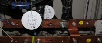
Examples of cable tags:
In accordance with the operating rules for electrical installations, any cable line must have digital and/or letter designations. Often, when an electrical circuit includes several parallel conductors, a combined alphanumeric system is used. In such a situation, the cable tag of each core contains the same numerical value, but different letters of the Cyrillic or Latin alphabet.
The cable sleeve and exposed wires must be marked with tags indicating the number, line name, operating voltage, cross-sectional area and brand of electrical components used. All tags are characterized by resistance to negative environmental factors. The maximum allowable distance between tags is 50 m.
When it comes to cable systems that are located in the same building and include several telecommunications rooms (according to the standard, such systems belong to administration class 2), the following network elements are subject to marking:
- sockets and socket panels,
- connecting equipment (patch panels and blocks),
- copper and/or optical cables,
- internal trunk cables, their termination points,
- consolidation points,
- ground planes (including main plane),
- telecommunication spaces (cross-connection and equipment rooms, their analogues),
- fire-fighting means.
TIA/EIA-606-A standard
makes the following requirements for marking marks: “Marking marks must be resistant to the environment at the installation site and have a service life no less than that of the component being marked. All markings on markers must be printed using a mechanical device." According to the standard, the use of paper labels with handwritten text is not allowed; all text must be printed strictly using printing devices.
To simplify the identification and maintenance of cable lines, markings are used.
Let us consider in more detail what requirements apply to each element of the cable system.
Telecommunication sockets and socket panels
Clause 5.1.2 of the standard states that each socket or connector must have a unique building-wide identifier. The socket must contain a cable line identifier in FS-AN
, where:
F
is the number of the floor with the telecommunications room (TC), indicated by a number;
S
- a letter indicating a shopping center within one floor or a certain space;
A
- letter designation (up to two letters) identifying the patch panel or cross-connect panel;
N
- digital designation (two to four digits) of the port of the patch panel or part of the cross-connect panel on which this line is installed.
Example of wall socket markings
An example of marking a switching socket
Patch and crossover panels
Clause 5.1.2 states that each port on a patch panel or distribution panel must have a label that contains the AN portion that was used in the patch socket identifier, FS-AN. The condition is met by assigning variable A a letter indicating the panel in the rack, and variable N - 2-4 numbers indicating each individual port of this panel.
Horizontal cables
Clause 5.1.2 of the standard also specifies the requirements for cable line marking. The cable line must be marked at both ends at a distance of no more than 30 cm from the edge. The horizontal cable line identifier is an FS-AN format marker (see above for detailed description).
Example of cable line marking
Internal trunk cables
When marking trunk lines, you should refer to clause 6.1.1 of the standard.
Each section of trunk cable connecting telecommunications premises must have a unique label. Also, as in the horizontal subsystem, markers in the main lines must be applied to both ends at a distance of 30 cm from the edge. The trunk ID must be in the format FS1/FS2-N
, where:
FS1
is the identifier of the telecommunications room in which the first end of the cable line is installed;
FS2
is the identifier of the telecommunications room in which the second end of the cable line is installed;
N
is the alphabetic or numeric designation of the main cable itself; it can be up to 2 characters long.
Trunk cable installation points
Clause 6.1.2 of the standard also describes the requirements for marking the main cable installation points. Each backbone patch panel port must have its own unique label, which is in the format FS1/FS2-ND
. The FS1/FS2-N part is the trunk cable identifier, and the D is the designation for a specific copper cable or single fiber optical cable.
This mark should be positioned in such a way that it can be easily determined which copper cable or optical fiber corresponds to it. It is allowed to mark the patch panel with part of the FS1/FS2-N label for ease of identification and to save space for marking, and with part D the port or optical adapter panel is marked directly.
To avoid confusion about how lines should be marked, the TIA/EIA-606-A standard was developed.
Grounding plates
Sections 5.1.3 and 5.1.4 of the TIA/EIA-606-A standard state that each ground bus that belongs to a common ground loop must be individually labeled. The grounding busbar label has the format FS-TGB, where FS is the identifier of the telecommunications room in which the busbar is located; TGB is an abbreviation for Telecommunications Grounding Busbar.
Telecommunications premises
Each telecommunications room located in the building must have a unique format label - FS.
It must be placed indoors in such a way that all people can easily find it. We have reviewed all the basic rules for marking cable system elements, which will help facilitate network administration. Now let's turn to the markers themselves and their varieties. Network elements such as patch panels and sockets most often have special places for marking, which simplifies the entire process and does not require additional costs. But when it comes to cable lines, it is necessary to use special markers. These can be either simple pieces of paper printed on a printer or flexible stickers made of polyvinyl chloride.
In the case of paper markers
A common problem is that the adhesive base dries out.
This leads to the fact that the markers simply fall off the cable, and it becomes impossible to identify it. To avoid this, you can use tubular markers
. These markers are made of polyvinyl chloride and are placed directly on the cable, which eliminates the possibility that they will somehow fall off.
Paper markers
Tubular markers NMC-CMR-1-YL-500 NIKOMAX
Marking goes along with the laying of cable lines. Just like marking, well-carried cable installation helps to avoid problems with line identification or maintenance in the future.
For the most part, the bulk of the cable is laid on metal trays or boxes. But it is not always possible to install an entire tray, or it becomes necessary to make a branch of several cables, for which it is not practical to lay additional cable-supporting elements. A large number of different accessories have been developed for such situations. Consider some of them.
Each telecommunications room located in the building must have a unique FS format tag.
Bases for fastening cables and ties
Quite often, when installing a single cable or when there is a small bundle, a combination of cable ties and bases is used. This method helps to lay the installation along the walls/ceiling in a small space. There are mainly two types of such bases used - self-adhesive and with a mounting hole.
Bases with clamps
Another type of base designed for organizing bundles or individual cables is base with clamps. They have similar functionality to the previous bases, but differ in design. A special clip-retainer is analogous to a cable tie.
Base with clasp NMC-CHSxx-BK-100 NIKOMAX
R-mounts
We will also touch on R-shaped fastenings.
They are used when installing a small amount of cable along the wall. For the most part, these fasteners are used for single cable installations, since they have a small internal diameter and are not designed for heavy loads. All the components discussed will help not only organize cable routes or small branches, but they can also help in organizing the workplace.
To summarize, we can say that both labeling and high-quality organization of the cable network are very important points that are worth paying attention to, even if we are talking about a small project. After all, the time and money spent will pay off double if it is necessary to modernize or maintain the network.
Author of the article: Igor Nikolaychuk
Purposes of wire markings
This process can significantly simplify electrical installation work, planned or emergency repairs, and maintenance of facilities and cable lines during operation. Another functional purpose is to reduce the likelihood of emergency situations and accompanying injuries to working personnel.
The cable is marked during the manufacturing process. The manufacturer must choose the color for the insulating sheath of the wire in accordance with international or domestic standards specified in PUE, PTEEP, GOSTs and other documentation. The data displayed on the outer sheath of the cable indicates information on several parameters:
- number of wires;
- cross-sectional area of the entire cable;
- insulating materials used;
- wire materials, etc.
Such marking, although necessary, is not sufficient to increase safety during the operation of cable lines. Based on it, maintenance specialists will not be able to draw clear conclusions about the purpose of the entire system or a specific section of electrical wiring. Therefore, when performing electrical installation work, additional abbreviations are applied to the cable, adding information about the purpose of the circuit to the characteristics.
Thanks to this, tags with the following data appear on the insulation:
- cable brand;
- purpose;
- the object associated with it;
- line length and other information if necessary.
Cable tags greatly simplify such marking, making it convenient and as fast as possible. They are selected depending on the diameter, characteristics and insulating materials on the wire. They may differ in a number of parameters, but have a common purpose and are capable of storing inscriptions for long periods of use.
What is written on cable lines when installing cable lines?
Date: November 15, 2009 |
Category: Questions and Answers, Electrical installation Tags: Cable, Cable tags, Cable brand, Electrical installation This material was prepared by specialists.
Do you need electrical installation or electrical measurements? Call us! Dmitry Please tell me what they say on the cable labels 0.4 sq. Do I need to indicate the length of the cable line? Answer: When installing cable lines, cable tags must be installed on them, indicating the number and name of the cable line, voltage, brand and cross-section of the cable.
The length of the cable line is not indicated on the tags.
PUE-6 2.3.23. Each cable line must have its own number or name. If a cable line consists of several parallel cables, then each of them must have the same number with the addition of the letters A, B, C, etc. Openly laid cables, as well as all cable terminations, must be equipped with tags indicating on the tags of cables and terminations the brand, voltage, cross-section, number or name of the line; on the coupling tags - coupling numbers and electrical installation dates. Tags must be resistant to environmental influences. On cables laid in cable structures, tags must be located along the length at least every 50 m.
PTEEP 2.4.5 Each CL must have a passport, including the documentation specified in clause 2.4.2. dispatch number or name. Openly laid cables, as well as all cable couplings, must be labeled; the cable tags at the beginning and end of the line must indicate the brand, voltage, cross-section, number or name of the line; on the coupling tags - coupling number, installation date. Tags must be resistant to environmental influences. They should be located along the length of the line every 50 m on openly laid cables, as well as at turns of the route and in places where cables pass through fire-resistant partitions and ceilings (on both sides).
SNIP 3.05.06-85 3.22 Wires and cables laid in boxes and on trays must be marked at the beginning and end of the trays and boxes, as well as at the places where they are connected to electrical equipment, and cables, in addition, also at turns of the route and at branches.
3.103 Each cable line must be marked and have its own number or name.
3.104 Labels must be installed on openly laid cables and cable joints. On cables laid in cable structures, tags must be installed at least every 50-70 m, as well as in places where the direction of the route changes, on both sides of passages through interfloor ceilings, walls and partitions, in places where cables enter (exit) into trenches and cable structures. On hidden cables in pipes or blocks, tags should be installed at the end points at the end couplings, in the wells and chambers of the block sewer system, as well as at each connecting coupling. On hidden cables in trenches, tags are installed at the end points and at each coupling.
Other and useful information
Other and useful information
Requirements for types and methods of attaching tags
In addition to the placement of tags, all information about the markings produced on cable lines and communication devices is recorded in a special journal. Such records are regularly updated depending on changes that have occurred in the network structure.
Like cable, tags are made into specific shapes from a variety of materials. These can be ordinary labels, self-adhesives, plastic seals or polymer products used for high-quality and reliable marking of a bundle of several cores or one wire.
Ley Line Markers
In accordance with GOST, plastic plaques are made in square, round or triangular shapes. They are used in open areas of cable routes and circuit components. The tags have two holes through which the wire or core should be threaded, after which it is securely clamped and fixed in the desired position.
Cable lines - marking requirements
Cable lines are an integral part of electrical and communication networks. When laying any open cables, including power cables in cable structures (cable tunnels, floors, overpasses, etc.), markings are required on the cable sheath. Power routes are often bundles of cables laid in parallel, the main purpose of marking which is ease of operation and repair of cable lines.
Unlike the factory marking of cable products, which is applied to the outer sheath and carries information about the features of the product, the marking of electrical installation cables is applied to explain the purpose of the cable. It must correspond to the information reflected in the cable log compiled when laying electrical cables. Labeling rules and the basic requirements for it are reflected in the following regulatory documents:
- current edition of the rules for electrical installations – clause 2.3.23;
- rules for technical operation of consumer electrical installations – clause 2.4.5;
- SNiP 3.05.06-85 – pp. 3.103 – 3.106.
According to the requirements of all three documents, marking is carried out by installing tags on laid cables and cable joints.
Features of cable line marking
Taking into account the above-mentioned tag rules, the following are established:
- at the beginning and end of the cable line;
- in places where couplings are installed;
- at points of change in cable direction;
- along the entire length of the line at a distance of no more than 50 m;
- on both sides where obstacles pass (walls, ceilings, etc.).
When laying cables in trenches, tags are installed next to the end couplings; in addition, they must be placed on the connecting couplings.
Tag markers installed along the entire cable line must contain the following information:
- cable number according to technical documentation;
- type of cable products used;
- the number of current-carrying conductors and their cross-section;
- numbers of cabinets between which the cable is connected, indicating the source and consumer;
- the length of the cable.
For connecting couplings, the marker indicates the number of the connection itself and the date when it was installed.
Tag markers differ in their geometry and material of manufacture. Due to their purpose, they come in square, round and triangular shapes:
- square mark the power cables of networks less than 1000 volts;
- round tags are used for marking high-voltage lines (from 1 kV and above);
- Triangles mark current-carrying lines of control cables.
Often, a bundle contains several dozen conductive lines; markers of this size get tangled, interfere with each other, and even get destroyed. In such situations, you can use smaller tags with a special fastening, which indicate only the cable number.
Tags are made from various materials: steel, aluminum or plastic. For rooms with high humidity or aggressive environments, only plastic tags are allowed. Today, a large number of building materials are produced, including those for electrical installations, so tags of any shape made of wear-resistant plastics or PVC are easier to buy.
Designations may be applied in any way that prevents abrasion or accidental damage to the inscriptions. This can be engraving on metal surfaces or burning with subsequent filling with dyes on plastic; for rooms with normal conditions, symbols are often applied with indelible paints. The simplest, cheapest and fastest way to apply information to tags today is considered to be the use of special printers.
See also other articles:
If you install stranded wires, the core of which can contain from several to several dozen thin wires, under a screw or other fastening, only by removing the insulation, it will not be possible to achieve high-quality contact.
The resolution of the dispute is suggested by the rules for the installation of electrical equipment (PUE) clause 1.7.144, which prohibits the connection of protective conductors with a loop; however, the desire to save on expensive cables and installation work pushes many electricians to violate them. So what is the danger? Why are PUEs so uncompromising regarding daisy chain connections?
Main types of cable markers
A marking tag in accordance with international standards must be installed on open cable routes and power installations. If the wire is laid in structures specially designed for this purpose, then the distance between the markers can be 50-70 m. You cannot do without them in a number of other cases:
- when the route crosses various obstacles that make visual inspection difficult (interfloor ceilings, walls, partitions), then tags are placed on each side of the obstacle passed (for example, on both sides of the wall);
- at points where the direction of the cable line changes;
- in places where input or output from other structures is carried out.
Many manufacturers and electricians prefer cable tags made of plastic, since such material can withstand moisture for a long time without changing its properties.
Form of marking tags
The rules and regulations indicate information on the forms of tags, which were described above:
- triangular - installed in cable lines for control or signaling purposes;
- square – for power lines with voltage up to 1 kV;
- round – over 1 kV.
Label sizes
The most common brands of cable tags are U-134, U-135, U-136 and U-153. Let's compare their sizes and, depending on the data obtained, draw conclusions on possible use in systems:
- U-134 is used to mark power lines with voltages not exceeding 1000 V. The square tag with an area of 55x55 mm is equipped with two 11x3.5 mm grooves for fixing with a cable binder.
- U-135 is suitable for indicating information on electrical circuits with voltages over 1000 V. Round products with a diameter of 55 mm and similar grooves for cable binders.
- U-136 is used for marking signal and control wires. The triangular product has equal sides 62 mm long each. There are two slots for a cable binder of the same size.
- U-153 is used for power lines with voltages up to 1000 V. A square product with a length of 28 mm and a 5 mm hole is attached using a special wire.
Important! Many organizations either ignore the cable tagging process or perform it using free-form tags. The consequences of both decisions can cause frequent emergencies and injury to operating personnel.
Color coding of wires and cables
Generally accepted standards and rules for color marking the insulating sheath of wires allow you to quickly and accurately determine the operating parameters of a cable and understand in which systems and devices it can be used. The color marking regulations are prescribed by PUE and GOST.
It is noteworthy that the designation system will be different for cable networks with alternating current or direct current. Often the cable is made in different colors. Instead of a shell, color marking can be done using heat-shrinkable tubes (cambrics). Another option is colored electrical tape. The choice of color for phase and neutral wires should always be different!
For three-phase alternating power lines, the buses should be marked as follows:
- first phase – yellow;
- the second is green;
- the third is red.
In DC cable runs, color designations are chosen according to the charge, which can be positive or negative. In the first case, a wire with a red braid is selected, in the second, a wire with a blue braid. The system does not support phase and neutral wires, and for the middle wire a light blue conductor is usually used.
For power installations with voltage up to 1 kV and neutral, the following marking is carried out:
- working neutral wire – blue;
- grounding – yellow-green;
- combined zero – yellow-green with blue markers (or blue with yellow-green markers);
- phases - red, black and other colors depending on the quantity.
It is noteworthy that the wiring inside electrical appliances is red, in sockets - brown.
Cable line marking
Marking cable lines with tags is a traditional way of marking cables in accordance with GOST, SNiP. Tags are resistant to dampness, dirt and other environmental influences. Our tags are suitable for automated application of information using a thermal transfer printer. The printing is applied either to the tag itself or to a self-adhesive label glued to the tag. The text does not wash off or fade. Operating temperature from -40°С to +90°С.
Types of cable tags
- square tags U134 for power cable up to 1000 volts
- round tags U135 for power cables over 1000 volts
- triangular tags U136 for control cable
Marking of wires and cables corresponds to PUE, SNiP, PTE EP.
Characteristics
| Name | Kit contents | Operating temperature | Installation method | ||
| 1 | 2 | 3 | |||
| 3in1 kit | tag | label | ribbon | from -40°С to +90°С | clamp, tie, rope |
| 2in1 kit | tag | – | ribbon | from -40°С to +90°С | clamp, tie, rope |
Application
Download a leaflet on the use of tags for marking cable lines in PDF format.
Video
Printing cable tags on the cab EOS1 printer
Normative base
Excerpts from documents regulating the use of cable tags.
Requirements for the production of tags TU 36-1440-82
Marking tags for cable lines are manufactured in accordance with TU 36-1440-82 : • Square tag U-134 – intended for power cables up to 1000V; • Round tag U-135 – intended for power cables over 1000V; • Triangular tag U-136 – designed for control cables.
| Type | Purpose of the tag | Dimensions, mm | Weight of tags 1000 pcs., kg | ||
| A | H | S | |||
| tag U-134 | For power cables up to 1000 V | 55 | – | 0,8 | 3,8 |
| tag U-135 | For power cables with voltages above 1000 V | 0,8 | 3,0 | ||
| tag U-136 | For control cables | 62 | 55 | 0,8 | 2,2 |
SNIP 3-05-06-85 “Electrical devices”
SNIP 3-05-06-85 “Electrical technical devices” came into force on July 1, 1986 (Resolution of the USSR State Construction Committee dated December 11, 1985 N 215).
P. 3.22. Wires and cables laid in boxes and on trays must be marked at the beginning and end of the trays and boxes, as well as at the points where they are connected to electrical equipment, and the cables, in addition, also at route turns and branches. Marking of cable lines P. 3.103. Each cable line must be marked and have its own number or name. P. 3.104. Labels must be installed on exposed cables and cable joints. On cables laid in cable structures, tags must be installed at least every 50 - 70 m, as well as in places where the direction of the route changes, on both sides of passages through interfloor ceilings, walls and partitions, in places where cables enter (exit) into trenches and cable structures. On hidden cables in pipes or blocks, tags should be installed at the end points at the end couplings, in the wells and chambers of the block sewer system, as well as at each connecting coupling. On hidden cables in trenches, tags are installed at the end points and at each coupling. P. 3.105. Tags should be used: in dry rooms - made of plastic, steel or aluminum; in damp rooms, outside buildings and in the ground - made of plastic. Designations on tags for underground cables and cables laid in rooms with a chemically active environment should be made by stamping, punching or burning. For cables laid in other conditions, markings may be applied with indelible paint. P. 3.106. Tags must be secured to the cables with nylon thread or galvanized steel wire with a diameter of 1 - 2 mm, or plastic tape with a button. The place where the tag is attached to the cable with wire and the wire itself in damp rooms, outside buildings and in the ground must be covered with bitumen to protect it from moisture.
Wire and cable marking methods
When choosing marking products, electricians are guided by operating conditions, capabilities and technical parameters of tags, availability of the necessary equipment and manufacturing materials.
Before installing the wire
In many situations, cable markings are placed on routes after installation. However, in some cases it becomes necessary to do this much earlier. The most obvious example is confined space or working at dangerous heights.
In such situations, the following marking products can be used:
- PVC tubes and cambrics of different diameters, on which information about the line is printed (they can be additionally protected with transparent tape, which simplifies fixation and increases protection);
- heat shrink tube for insulation;
- A simpler and cheaper method is to write the information on a piece of thick paper, attach it to the cable and secure it with transparent tape or a clamp.
After installing the wire
If a wire or cable is located in a switchgear, then the designations are applied using one of the following methods:
- Before connecting the contact tracks to the wires, polyvinyl chloride cambrics and heat-shrinkable tubes are put on the latter.
- A self-laminating marker is a small plate, on one side of which an adhesive coating is applied for fixing to the cable, and on the other there is a matte surface for various inscriptions. The tag must be glued to the insulation and additionally wrapped with transparent tape (special electrical tape). The selected materials can withstand high temperatures and are characterized by resistance to aggressive environments.
- Cable tags are often the best option. The products are made of polymer materials and can be attached to the cable sheath in several ways. Plastic withstands high temperatures, protecting inscriptions with important information. The sizes, shapes and contents of tags are selected in accordance with PUE, PTEEP and SNiP.
- For small diameter cables, polymer flags with standard markings can be used.
- The sleeve and container involve the use of a plastic carrier that is attached to the wire, after which a marker with printed symbols is placed inside it.
- Clips and rings - for fixing with letters and numbers up to three or four characters.
- Self-adhesive nylon markers.
Cable tags
To properly install and operate electrical wiring and other devices, you must have at least minimal knowledge of the standards for cable lines and electrical installations. There are many provisions and instructions governing the actions of an electrician and installer when working on electrical lines of various voltages. Such documents also include the Rules for marking wires on the main line and in the distribution cabinet. This article discusses the types of tags for cable markings, as well as the conditions under which the label should be on the surface of the wire.
Cable tags
Types of cable tags
Cable marking can be carried out with factory-made or self-produced tags, but their form must be strictly observed within the framework of the regulations. Based on this standard, there are several types of tags used to mark cable lines, these include:
- Square badges with holes for fastening. These tags indicate lines with voltages up to 1000 V, most often these are routes for household purposes;
- Round tags are designed to identify electrical cables transmitting over 1000 V; these are industrial lines that require a high level of safety during installation and operation;
- To mark a low-voltage wire or control network, you will need a triangular-shaped tag with all sides equal to each other.
Alphanumeric designations
GOST specifies regulations for marking the external insulation of cable lines, thanks to which cords, cables and wires can be distinguished from each other. If there are no markings on the braid or they are not sufficient for maintenance and safety, then special tags with additional data are attached to the route.
According to the rules and recommendations prescribed in GOST, a wire is a product consisting of one or more cores, which are protected with insulation along their entire length. The cores can be produced without insulation. A cable is defined as several conductors insulated separately from each other, placed under a single sealed sheath made of metal or polymer materials. A cord consists of two or more flexible conductors that are connected together by twisting or braiding. The cores are fixed along their entire length, and the braid is made from non-metallic materials.
All cables are divided into several groups:
- power;
- signaling and control;
- installation;
- radio frequency;
- connected.
You can decipher the alphanumeric symbols on the insulation yourself.
The first letter in the abbreviation indicates the material the core is made of. The letter “A” at the beginning indicates that the current-carrying conductor is made of aluminum. The absence of such a letter means that it is made of copper.
The second letter indicates the scope of application of the product. If the second letter in the abbreviation is missing, then such a cable is considered to be power.
The third letter is used to indicate the degree of flexibility of the product. Its absence indicates a single-core wire, the presence of the letter “G” indicates a flexible multi-core wire.
The fourth letter allows you to designate the material used to make the insulation. Windings are made from different materials, so more specific designations are used for it.
The fifth letter indicates the material used to make the outer shell and the presence or absence of an armored hull.
The sixth letter can be used to indicate the protective cover, the purpose of the layer and the structure as a whole.
Thanks to capital letters, you can indicate certain features of the cable line, the presence of certain properties. After the letter designations there are numbers. The first number indicates the operating voltage (“1” – 1 kV, without a number – 600 V), the second – the number of cores (1-37), the third – cross-sectional area.
Marker fastening
Cable tags can be attached to wires using various fasteners. The most common are synthetic thread, plastic tapes with a latch, wire with an anti-corrosion coating, clips, etc. If you need to use ordinary steel wire for fastening, then it should first be coated with a protective layer of bitumen or paint to prevent corrosion. Ideally, you should use polyvinyl chloride insulated wire.
How to mark
The most reliable method of marking cable lines is stamping. On the other hand, this method requires the presence of special equipment (a printer), which cannot always be used.
In many ways, the choice of a specific method depends on the material used to make the cable tag. You can also buy markers with already prepared symbols, sold in ribbons. They have cuts that allow you to quickly and accurately remove the desired label and fix it on the wire using an adhesive surface.
The inscriptions are made from waterproof paint or ink. If the electrical circuit is installed in rooms with high humidity levels or is constantly exposed to an aggressive environment, then the marking is applied by milling, punching, burning or stamping on plastic/metal.
For dry rooms with good ventilation or air conditioning, you can get by with marking using standard means - a pencil or felt-tip pen.
Marking of low-current cables – Low-current cables. Types and labeling. Device and features
PUE
clause 2.3.23. Each cable line must have its own number or name. If a cable line consists of several parallel cables, then each of them must have the same number with the addition of the letters A, B, C, etc.
Openly laid cables, as well as all cable terminations, must be equipped with tags indicating on the tags of cables and terminations the brand, voltage, cross-section, number or name of the line; on the coupling tags - coupling numbers and installation dates. Tags must be resistant to environmental influences.
On cables laid in cable structures, tags must be located along the length at least every 50 m.
SNIP 3-05-06-85
clause 3.22. Wires and cables laid in boxes and on trays must be marked at the beginning and end of the trays and boxes, as well as at the points where they are connected to electrical equipment, and the cables, in addition, also at route turns and branches. 3.103. Each cable line must be marked and have its own number or name.3.104. Labels must be installed on exposed cables and cable joints.
On cables laid in cable structures, tags must be installed at least every 50 - 70 m, as well as in places where the direction of the route changes, on both sides of passages through interfloor ceilings, walls and partitions, in places where cables enter (exit) into trenches and cable structures. On hidden cables in pipes or blocks, tags should be installed at the end points at the end couplings, in wells and chambers of block sewerage, as well as at each connecting coupling.
On hidden cables in trenches, tags are installed at the end points and at each coupling.
3.105. Tags should be used: in dry rooms - made of plastic, steel or aluminum; in damp rooms, outside buildings and in the ground - made of plastic.
Designations on tags for underground cables and cables laid in rooms with a chemically active environment should be made by stamping, punching or burning. For cables laid in other conditions, markings may be applied with indelible paint.
3.106. Tags must be secured to the cables with nylon thread or galvanized steel wire with a diameter of 1 - 2 mm, or plastic tape with a button. The place where the tag is attached to the cable with wire and the wire itself in damp rooms, outside buildings and in the ground must be covered with bitumen to protect it from moisture.
PTE EP
2.3. Each CL must have the documentation specified in paragraph 2.2 of this chapter, which is documented in a separate file (passport), the corresponding dispatch number and name. Openly laid cables, as well as all cable couplings, must have tags with designations: at the end and at the beginning of the lines, the tags must indicate the cable brand, voltage, cross-section, numbers or names of the lines; on the coupling tags - coupling number, installation date. Tags must be resistant to environmental influences. Tags must be attached along the entire length of the cable line every 50 m on openly laid cables, as well as on route turns and in places where cables pass through fire-resistant partitions and ceilings (on both sides).
You can choose and buy cable tags
useful things, stickers for the server room
alabels.com.ua
Cable tags: 10 requirements for marking live wires
It is customary to use special tags for marking cables. Today, the range of conductive cables is incredibly large. In order for the consumer to easily select products, and for electricians and repairmen to quickly understand which cable is in front of them, there is a standardized conductor marking system. Read below about the basic rules and requirements for marking electrical installation cables.
Requirements for marking cables when installing electrical panels are regulated by GOST 23594-79 dated 07/01/1980. According to the standard, each conductive cable or wire must have a marker, presented in the form of a tag or PVC tape.
Marking of wires and cables during installation, as a rule, must comply with GOST requirements
In addition, the following requirements are put forward for cable marking:
- For marking, letters of the Russian and Latin alphabets and Arabic numbers should be used.
- The inscriptions on the markings must be in capital letters, block letters, and be legible (do not contain serifs, have sufficient letter spacing). At the end of numerical designations, a dot should be placed to the right of the final digit.
- The length of the tag or label should not be less than 2.5 cm.
- The marking consumption rate should be one marker for every 3 meters of cable.
- The marking should be applied to the cable at a distance of 5-7 cm from the connecting elements.
At the same time, each power line must have a number or letter designation. For lines consisting of several parallel conductors, the designation must be double. So, each of the conductors must be designated by the same number with the addition of a letter sign (for example, A, B, C, etc.).
Common labeling mistakes
Let's list three main mistakes:
- The most common one is caused by novice electricians or experienced specialists due to inattention. In the process of screwing the wire to the shield and terminals, the craftsmen simply forget to put a heat-shrinkable tube with markings (tube) on the wires. Because of this, you have to unscrew the attached wiring and put the products on again.
- Often craftsmen confuse the PEN conductor with a grounding cable. The fact is that both elements have identical color markings, so you need to inspect them more carefully.
- If the panel is located outside the site, then it is necessary to conclude an agreement with the electrical energy supplier. You must have on hand technical documentation with a diagram and confirmation of compliance with the requirements of the PUE, PTEEP and other regulatory acts. Otherwise, you may face claims from Rostekhnadzor.
Let's summarize: in accordance with the requirements and regulations prescribed in international and domestic standards, all power installations and cable lines without exception must be marked. The need for marking is not affected by either the voltage values or the location of installation (laying) of the circuit.
Qualified specialists will agree to carry out repair work and engage in maintenance of emergency areas only if sufficient information about the parameters of the line is provided. This is exactly what is contained on the cable tags.
To properly install and operate electrical wiring and other devices, you must have at least minimal knowledge of the standards for cable lines and electrical installations. There are many provisions and instructions governing the actions of an electrician and installer when working on electrical lines of various voltages. Such documents also include the Rules for marking wires on the main line and in the distribution cabinet. This article discusses the types of tags for cable markings, as well as the conditions under which the label should be on the surface of the wire.
Cable tags
Cable marking with tags according to PUE
clause 2.3.24. Each cable line must have its own number or name. If a cable line consists of several parallel cables, then each of them must have the same number with the addition of the letters A, B, C, etc. Openly laid cables, as well as all cable terminations, must be equipped with tags indicating on the tags of cables and terminations the brand, voltage, cross-section, number or name of the line; on the coupling tags - coupling numbers and installation dates. Tags must be resistant to environmental influences. On cables laid in cable structures, tags must be located along the length at least every 50 m.
6.3.2 Installation of electrical wiring on cable trays and cable ladders, in cable and special cable boxes
6.3.2.11 Conductors laid in boxes and on trays must be marked at the beginning and end of the routes of trays and boxes within one room, open installation or structure , as well as in places where they are connected to electrical equipment. Cables must also be marked at route turns and branches. 6.3.6 Laying wires and cables in steel pipes 6.3.6.12 At the end points of the wiring, wires and cables must be marked in accordance with the design. 6.3.8 Installation of auxiliary circuits 6.3.8.3 The devices should be marked before installing the auxiliary circuit wires according to the electrical connection diagram. If installation is complicated, then, as an exception, devices can be marked after installation is completed. The wires of the auxiliary circuits should not cover the marking areas of the devices. 6.3.8.11 Wires and cores of control cables connected to assemblies (rows) of clamps must be marked according to the diagrams. Control cables must be marked at the ends, in places of branching and intersection of cable flows, when passing through walls, ceilings, etc. The ends of the free conductors of control cables must be insulated. 6.3.8.14 The tag is fixed on the cable below the cutting at a distance of no more than 50 mm using mounting tape or ties (clamps). The distance from the cable bandage to the tag should be no more than 20 mm. It is recommended to print inscriptions on cable tags and on PVC pipes using a cable printer. 6.3.8.15 The inscriptions on the PVC tag of each cable must contain on the front side: – cable number; – number of the cable start cabinet; – number of the cable end cabinet; on the reverse side: – cable type; – number of cable cores; – cross-section of cable cores; - length of cable. The font size of the cable number should be two sizes larger than the font of other inscriptions. 6.3.8.21 Inscriptions on PVC tubes for marking the cores of control cables must contain: – cable number; – core number; – cabinet terminal number, without indicating the terminal number. The font size of the core number should be two sizes larger than the font of other inscriptions. 6.3.8.22 The marking of cable cores must be placed in such a way that it is easy to read. It can be arranged in a column or row and read from top to bottom or left to right. 6.4.8 Marking of cable lines 6.4.8.1 Each cable line must be marked and have its own number or name in accordance with the design documentation. 6.4.8.2 Labels must be installed on openly laid cables and cable joints. On cables laid in cable structures, tags must be installed at least every 50 - 70 m, as well as in places where the direction of the route changes, on both sides of passages through interfloor ceilings, walls and partitions, in places where cables enter (exit) into trenches and cable structures. On hidden cables in pipes or blocks, tags should be installed at the end points at the end couplings, in the wells and chambers of the block sewer system, as well as at each connecting coupling. On hidden cables in trenches, tags are installed at the end points and at each coupling. 6.4.8.3 For cables with voltages over 1000 V, the tags must be round, for voltages up to 1000 V - square, for the control cable - triangular. 6.4.8.4 Tags should be used: in dry rooms - made of plastic, steel or aluminum; in damp rooms, outside buildings and in the ground - made of plastic. Designations on tags for underground cables and cables laid in rooms with a chemically active environment should be made by stamping, punching or burning. For cables laid in other conditions, markings may be applied with indelible paint. 6.4.8.5 Tags must be secured to cables with buckles or mounting tape with a button. 6.4.8.6 When laying a cable line, it is recommended to install intelligent electronic markers along the route, including in places where the cable line route turns, the location of connecting couplings and horizontal inclined drilling pits.
2.4.5. Each cable line must have a passport, including the documentation specified in clause 2.4.2, dispatch number or name. Openly laid cables, as well as all cable couplings, must be labeled; the cable tags at the beginning and end of the line must indicate the brand, voltage, cross-section, number or name of the line; on the coupling tags - coupling number, installation date. Tags must be resistant to environmental influences. They should be located along the length of the line every 50 m on openly laid cables, as well as at turns of the route and in places where cables pass through fire-resistant partitions and ceilings (on both sides).
The differences between SNiP 3.05.06-85 and SP 76.13330.2016 regarding cable marking are given in this article.
Types of cable tags
Cable marking can be carried out with factory-made or self-produced tags, but their form must be strictly observed within the framework of the regulations. Based on this standard, there are several types of tags used to mark cable lines, these include:
- Square badges with holes for fastening. These tags indicate lines with voltages up to 1000 V, most often these are routes for household purposes;
- Round tags are designed to identify electrical cables transmitting over 1000 V; these are industrial lines that require a high level of safety during installation and operation;
- To mark a low-voltage wire or control network, you will need a triangular-shaped tag with all sides equal to each other.
Form of marking tags
What tags should be in terms of form are determined by the Electrical Installation Rules. Tags for cables and wires are:
- square, which are used on household power lines with a voltage not exceeding 1000 V;
- round, used for marking power lines with voltages above 1000 V. We are talking about industrial lines that need to ensure a high level of safety required during their installation and operation;
- triangular - similar tags in the shape of a triangle with equal sides are used to designate low-voltage wires.
Requirements for inscriptions on tags
Tags on the cable, secured with clamps or threaded through the wire, must be signed in a certain way; this rule is regulated by the rules of the PUE. In accordance with this document, the following data is applied to the label:
- Cable or line number. This is information that contains data about the direction of the highway, what it feeds, and what level of protection is required. During the wiring installation process, an object passport is drawn up, which indicates the buildings or premises powered by this line. They are assigned numbers, which will subsequently be written on the tag itself; during the service process, the technician will be able to look at the markings of the cables and, by comparing them with the object’s passport, understand where this or that line leads;
- Brand and cross-section of wire. Since space on the tag is limited, the designation is written abbreviated, with a minimum number of characters. For example, a vinyl-coated cable with a cross-section of 3*2.5 is briefly designated VVG-3/2.5;
- Line voltage. This is a mandatory parameter, since it is not clear from the outer sheath of the cables what voltage the current flows through it, respectively, and what level of protection is required during repair work;
- The beginning and end of cable lines. For more accurate information about possible losses on the main line after its installation, a designation of the total length is applied. After reading the data, the technician servicing the wire line will be able to accurately calculate the resistance and level of voltage loss in the network.
Labels on tags
All of the information listed is basic and mandatory. It is not prohibited to place additional information on the tag that characterizes the electrical main, for example, the date of laying. In addition, when placing a tag on the coupling, it is necessary to place the date of installation of the wire, since the coupling has its own resource, which will be calculated based on this indicator.
Inscriptions on metal tags are most often made by engraving with a special pencil or indelible paint. Plastic products are signed with a permanent marker or indelible paint. Also, when placing a tag using wire on a highway, it is necessary to additionally protect metal objects with bituminous composition or any other paint, otherwise the wire will rust and collapse, and the tag will be lost. Nylon thread is best suited for fastening; it is not afraid of temperature changes and high humidity.
Tag for threading onto wire
Recently, to indicate the cable on the line, many electricians began to use stickers that already have inscriptions informing about the voltage, as well as empty spaces in which additional data is written. Such stickers are very convenient, since the master does not waste time making markings, but simply glues the element onto the finished tag and continues installation.
What do the tags tell you?
The PUE determines not only what tags should be on the cables, but also the mandatory information that they must contain, namely:
- power line number - allows you to find out its direction, identify the object powered by it, and determine mandatory safety measures. The installation of electrical wiring is accompanied by the creation of a passport for the building being serviced, a house in which all the premises supplied with electricity from this line are indicated. They receive numbers, they are applied along with other marking information. The presence of marking labels makes it much easier for specialists to maintain lines;
- wire brand and cross-section - space on the tag is limited, so the designation is carried out with a minimum number of characters. The cable brand is indicated by a generally accepted abbreviation;
- voltage level is an important mandatory characteristic, since it is difficult to understand just from the outside of the cable what current it carries;
- the location of the beginning and end of the line - data on the total length of the electric main, with which an electrician can easily determine the resistance of the wiring and the level of voltage loss in it.
The above characteristics and parameters must be applied to the tags without fail. If there is free space on the labels, you can place there any additional parameters characterizing the cable, for example, the time of its installation.
Tags installed on couplings connecting cables must contain information about the date of installation.
Rules for placing tags on devices
When installing in closed channels or collectors, the tags must be located in inspection wells, regardless of their distance from each other. The part is attached on both sides of the collector to each of the route branches. It is also necessary to mark the turning sections of the line on both sides, indicating the direction of rotation and degree.
When wiring passes through ceilings indoors or under the road surface, an inspection box must be installed, and the wires are marked with plastic tags.
When laying electric lines through undeveloped territory or lands intended for agriculture, markings are installed along the entire route in the form of poles with tags, which are also marked with the characteristics of the power line. Such poles will act as an object for reference to the terrain, their coordinates are included in the route plan, and if necessary, it will be possible to accurately determine the location of the cable under the ground.
Thus, according to the rules and regulations, all power installations and cable lines are subject to mandatory labeling, regardless of their voltage type and location. In addition, any qualified craftsman will agree to carry out repair work in an emergency area only if he has sufficient information about the characteristics of the electrical line.
Cable marking with tags according to PUE
clause 2.3.23. Each cable line must have its own number or name. If a cable line consists of several parallel cables, then each of them must have the same number with the addition of the letters A, B, C, etc. Openly laid cables, as well as all cable terminations, must be equipped with tags indicating the brand, voltage, cross-section, number or name of the line on the tags of the cables and terminations; on the coupling tags - coupling numbers and installation dates. Tags must be resistant to environmental influences. On cables laid in cable structures, tags must be located along the length at least every 50 m.
clause 3.22. Wires and cables laid in boxes and on trays must be marked at the beginning and end of the trays and boxes, as well as at the points where they are connected to electrical equipment, and the cables, in addition, also at route turns and branches. 3.103. Each cable line must be marked and have its own number or name. 3.104. Labels must be installed on exposed cables and cable joints. On cables laid in cable structures, tags must be installed at least every 50 - 70 m, as well as in places where the direction of the route changes, on both sides of passages through interfloor ceilings, walls and partitions, in places where cables enter (exit) into trenches and cable structures. On hidden cables in pipes or blocks, tags should be installed at the end points at the end couplings, in the wells and chambers of the block sewer system, as well as at each connecting coupling. On hidden cables in trenches, tags are installed at the end points and at each coupling. 3.105. Tags should be used: in dry rooms - made of plastic, steel or aluminum; in damp rooms, outside buildings and in the ground - made of plastic. Designations on tags for underground cables and cables laid in rooms with a chemically active environment should be made by stamping, punching or burning. For cables laid in other conditions, markings may be applied with indelible paint. 3.106. Tags must be secured to the cables with nylon thread or galvanized steel wire with a diameter of 1 - 2 mm, or plastic tape with a button. The place where the tag is attached to the cable with wire and the wire itself in damp rooms, outside buildings and in the ground must be covered with bitumen to protect it from moisture.
2.3. Each CL must have the documentation specified in paragraph 2.2 of this chapter, which is documented in a separate file (passport), the corresponding dispatch number and name. Openly laid cables, as well as all cable couplings, must have tags with designations: at the end and at the beginning of the lines, the tags must indicate the cable brand, voltage, cross-section, numbers or names of the lines; on the coupling tags - coupling number, installation date. Tags must be resistant to environmental influences. Tags must be attached along the entire length of the cable line every 50 m on openly laid cables, as well as on route turns and in places where cables pass through fire-resistant partitions and ceilings (on both sides).