An inductor is a passive component of electronic circuits whose main purpose is to store energy in the form of a magnetic field. The property of an inductor is somewhat similar to a capacitor, which stores energy in the form of an electric field.
Inductance (measured in Henry) is the effect of creating a magnetic field around a current-carrying conductor. The current flowing through the inductor creates a magnetic field, which has a relationship with the electromotive force (EMF) that opposes the applied voltage.
The resulting reaction force (EMF) opposes the change in alternating voltage and current in the inductor. This property of an inductive coil is called inductive reactance. It should be noted that the inductive reactance is in antiphase to the capacitive reactance of the capacitor in the AC circuit. By increasing the number of turns, the inductance of the coil itself can be increased.
Stored energy in inductance
As you know, a magnetic field has energy. Just as there is a reserve of electrical energy in a fully charged capacitor, there is also a reserve of magnetic energy in an inductive coil through the winding of which current flows.
The energy stored in the inductor is equal to the expended energy necessary to ensure the flow of current I in counteracting the EMF. The amount of stored energy in the inductance can be calculated using the following formula:
where L is the inductance, I is the current flowing through the inductor.
The design and principle of operation of an inductor.
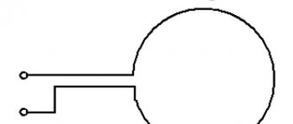
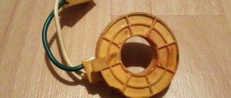
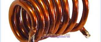
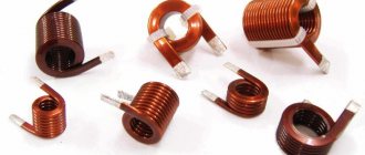
As is already clear from the name of the element, an inductor, first of all, is nothing more than a coil. That is, a certain number of turns of an insulated conductor. Moreover, the presence of insulation is the most important condition - the turns of the coil should not short-circuit with each other. Most often, the turns are wound on a cylindrical or toroidal frame:
The most important characteristic of an inductor is, naturally, inductance. By definition, inductance is the ability to convert the energy of an electric field into the energy of a magnetic field. This property of the coil is due to the fact that when current flows through the conductor, a magnetic field appears around it:
And here’s what the magnetic field that appears when current passes through the coil looks like:
In general, strictly speaking, any element in an electrical circuit has inductance, even an ordinary piece of wire. But the fact is that the magnitude of such inductance is very insignificant, in contrast to the inductance of coils. Actually, in order to characterize this value, the Henry (H) unit of measurement is used. 1 Henry is a fairly large value, so µH (microhenry) and mH (millihenry) are most often used. The inductance value can be calculated using the following formula:
L = \frac{\mu_0\thinspace \mu SN^2}{l}
Let's figure out what quantities are included in this expression:
- \mu_0 is the magnetic permeability of vacuum. This is a constant and it is equal to: \mu_0 = 4 \pi \cdot 10^{-7}\medspace\frac{Gn}{m}
- \mu is the magnetic permeability of the magnetic core material. A few words about what kind of core this is and what it is needed for. The point is that if the coil is wound not just on a frame (with air inside), but on a magnetic core, then the inductance will increase many times over. Judge for yourself - the magnetic permeability of air is 1, and for nickel it can reach 1100. So we get an increase in inductance by more than 1000 times
- S - cross-sectional area of the coil
- N - number of turns
- l - coil length
From the formula it follows that with an increase in the number of turns or, for example, the diameter (and, accordingly, the cross-sectional area), the inductance will increase. And as the length increases, it decreases. Thus, the turns on the coil should be placed as close to each other as possible, as this will lead to a decrease in length.
Now that the structure of the inductor , it’s time to consider the physical processes that occur in this element during the passage of electric current. To do this, we will consider two circuits - in one we will pass direct current through the coil, and in the other - alternating current.
Hydraulic model
The operation of an inductor can be compared to the operation of a hydraulic turbine in a flow of water. The flow of water directed through a turbine that has not yet been spun up will feel resistance until the turbine is completely spun up.
Next, the turbine, which has a certain degree of inertia, rotates in a uniform flow, practically without affecting the speed of water flow. If this flow is suddenly stopped, the turbine will still rotate by inertia, creating water movement. And the higher the inertia of a given turbine, the more it will resist changes in flow.
Power supply 0…30 V / 3A
Adjustable power supply assembly kit…
More details
Also, an inductive coil resists changes in the electric current flowing through it.
Inductance in electrical circuits
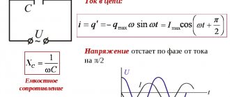
While a capacitor resists changes in alternating voltage, inductance resists alternating current. An ideal inductance will have no resistance to direct current, however, in reality, all inductive coils themselves have a certain resistance.
In general, the relationship between the time-varying voltage V(t) passing through a coil of inductance L and the time-varying current I(t) passing through it can be represented as a differential equation of the following form:
When a sinusoidal alternating current (AC) flows through an inductor, a sinusoidal alternating voltage (EMV) is generated. The amplitude of the EMF depends on the amplitude of the current and the frequency of the sinusoid, which can be expressed by the following equation:
where ω is the angular frequency of the resonant frequency F:
Moreover, the phase of the current lags behind the voltage by 90 degrees. In a capacitor, the opposite is true, where the current leads the voltage by 90 degrees. When an inductive coil is connected to a capacitor (series or parallel), an LC circuit is formed that operates at a specific resonant frequency.
Inductive reactance XL is determined by the formula:
where XL is the inductive reactance, ω is the angular frequency, F is the frequency in hertz, and L is the inductance in henry.
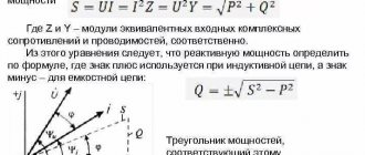
Inductive reactance is the positive component of impedance. It is measured in ohms. The impedance of the inductor (inductive reactance) is calculated by the formula:
Inductance
An electric current passing through a circuit creates a magnetic field around it. Magnetic flux Φ through the circuit of this conductor (it is called its own magnetic flux
) is proportional to the induction module B of the magnetic field inside the circuit \(\left( \Phi \sim B \right)\), and the magnetic field induction in turn is proportional to the current strength in the circuit \(\left( B\sim I \right)\ ).
Thus, the own magnetic flux is directly proportional to the current strength in the circuit \(\left( \Phi \sim I \right)\). This relationship can be represented mathematically as follows:
\(\Phi = L \cdot I,\)
where L
- proportionality coefficient, which is called
circuit inductance
.
- The inductance of a circuit
is a scalar physical quantity, numerically equal to the ratio of the own magnetic flux penetrating the circuit to the current strength in it:
\(~L = \dfrac{\Phi}{I}.\)
The SI unit of inductance is the henry (H):
1 H = 1 Wb/(1 A).
- The inductance of the circuit is 1 H if, at a direct current of 1 A, the magnetic flux through the circuit is 1 Wb.
The inductance of the circuit depends on the size and shape of the circuit, on the magnetic properties of the environment in which the circuit is located, but does not depend on the current strength in the conductor. Thus, the inductance of the solenoid can be calculated using the formula
\(~L = \mu \cdot \mu_0 \cdot N^2 \cdot \dfrac{S}{l},\)
where μ is the magnetic permeability of the core, μ0 is the magnetic constant, N
is the number of turns of the solenoid,
S
is the area of the turn,
l
is the length of the solenoid.
With the shape and dimensions of a fixed circuit remaining unchanged, the intrinsic magnetic flux through this circuit can change only when the current strength in it changes, i.e.
\(\Delta \Phi =L \cdot \Delta I.\) (1)
Inductor connection diagrams
Parallel connection of inductors
The voltage across each of the inductors connected in parallel is the same. The equivalent (total) inductance of parallel-connected coils can be determined by the formula:
Series connection of inductors
The current flowing through inductors connected in series is the same, but the voltage across each inductor is different. The sum of potential differences (voltages) is equal to the total voltage. The total inductance of series-connected coils can be calculated using the formula:
These equations are valid provided that the magnetic field of each coil does not affect neighboring coils.
Inductor quality factor
In practice, an inductor has a series resistance created by the copper winding of the coil itself. This series resistance converts the electric current flowing through the coil into heat, which leads to a loss of induction quality, that is, quality factor. Quality factor is the ratio of inductance to resistance.
The quality factor of the inductor can be found through the following formula:
where R is the winding's own resistance.
Inductor. Inductance formula
The basic formula for coil inductance is:
- L = inductance in henry
- μ 0 = permeability of free space = 4π × 10 -7 H/m
- μ g = relative permeability of core material
- N = number of turns
- A = Cross-sectional area of the coil in square meters (m2)
- l = coil length in meters (m)
Direct conductor inductance:
- L = inductance in nH
- l = conductor length
- d = conductor diameter in the same units as l
Air core coil inductance:
- L = inductance in µH
- r = outer coil radius
- l = coil length
- N = number of turns
Inductance of multilayer air core coil:
- L = inductance in µH
- r = average coil radius
- l = coil length
- N = number of turns
- d = coil depth
Flat Coil Inductance:
- L = inductance in µH
- r = average coil radius
- N = number of turns
- d = coil depth
Features of calculating inductive elements with cores
Unlike inductive elements without cores, the calculation of which took into account the magnetic flux penetrating only the current-carrying conductor, the magnetic flux of inductive elements with cores is almost completely closed to the cores. Therefore, when calculating the inductance of such elements, it is necessary to take into account the dimensions of the core and the material from which it is made, that is, its magnetic permeability.
The generalized formula for calculating inductive elements with cores can be expressed using the following expression
where ω is the number of coil turns,
RM – magnetic circuit resistance,
μa is the absolute magnetic permeability of the substance from which the core is made,
SM – cross-sectional area of the core,
lM – length of the average magnetic field line,
Thus, knowing the dimensions of the core, you can quite simply calculate the inductance. However, due to this simplicity of expression and the scatter in the magnetic permeability of the core material, the error in calculating the inductance will be 25% .
For cores with a complex structural configuration, the concept of effective (equivalent) dimensions is introduced, which take into account the features of the core shape: the effective path of the magnetic line le and the effective cross-sectional area Se of the core. Then the inductance of the coil with the core will be calculated by the formula
where ω is the number of coil turns,
μ0 – magnetic constant, μ0 = 4π*10-7,
μr – relative magnetic permeability of the substance,
Se is the effective cross-sectional area of the core,
le is the effective path of the magnetic line of the core.
Thus, calculating the inductance of inductive elements with cores comes down to finding the effective dimensions of the core. To simplify the determination of these core dimensions, auxiliary quantities called core constants were introduced:
C1 is the first constant of the core, which is equal to the sum of the ratios of the lengths of sections of the core that are homogeneous in cross-section to the cross-section of the core, measured in mm-1;
C2 is the second constant of the core, which is equal to the sum of the ratios of the lengths of sections of the core that are homogeneous in cross-section to the square of its cross-section, measured in mm-3;
where N is the number of dissimilar sections of the core,
lN – length of the Nth section of the core,
SN – area of the Nth section of the core.
Then the values of Se and le will be determined from the following expressions
In addition to inductance, using constants C1 and C2, the effective volume Ve is determined, which is required to determine the parameters of power inductive elements - transformers and chokes. If there is a need to calculate only the inductance L, then use only the constant C1 according to the following expression
where ω is the number of coil turns,
μ0 – magnetic constant, μ0 = 4π*10-7,
μr – relative magnetic permeability of the substance,
C1 is the first constant of the core, which is equal to the sum of the ratios of the lengths of sections of the core that are uniform in cross-section to the cross-section of the core.
Despite the rather complex formulations and formulas, calculating inductance using them is quite simple.
There are quite a few types of cores available that have different design features and properties; let’s look at some of them.
Inductor design
An inductor is a winding of conductive material, usually copper wire, wound around either an iron-containing core or no core at all.
The use of materials with high magnetic permeability, higher than air, as a core helps to retain the magnetic field near the coil, thereby increasing its inductance. Inductive coils come in different shapes and sizes.
Most are made by winding enameled copper wire over a ferrite core.
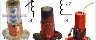
Some inductive coils have an adjustable core that allows the inductance to vary.
Miniature coils can be etched directly onto the PCB in a spiral pattern. Low-value inductors can be located in microcircuits using the same technological processes used to create transistors.
Toroidal Coil Inductance
For a toroidal coil wound on a core made of a material with high magnetic permeability, you can approximately use the formula for an infinite straight solenoid:
where is an estimate of the length of the solenoid ( is the large radius of the torus).
The best approximation is given by the formula
where a rectangular core with an outer radius R
and inner radius
r
, height
h
.
Mutual induction
Mutual induction (mutual induction) is the occurrence of an electromotive force (induction emf) in one conductor due to a change in current strength in another conductor or due to a change in the relative position of the conductors. Mutual induction is a special case of a more general phenomenon - electromagnetic induction. When the current in one of the conductors changes or when the relative position of the conductors changes, a change occurs in the magnetic flux through the (imaginary) surface “stretched” over the contour of the second, created by the magnetic field generated by the current in the first conductor, which, according to the law of electromagnetic induction, causes the occurrence of an emf in the second conductor. If the second conductor is closed, then under the influence of mutual induction emf an induced current is formed in it. Conversely, a change in current in the second circuit will cause an emf to appear in the first. The direction of the current arising from mutual induction is determined by Lenz's rule. The rule indicates that a change in current in one circuit (coil) is counteracted by another circuit (coil).
The more part of the magnetic field of the first circuit penetrates the second circuit, the stronger the mutual induction between the circuits. On the quantitative side, the phenomenon of mutual induction is characterized by mutual inductance (mutual induction coefficient, coupling coefficient). To change the magnitude of the inductive coupling between the circuits, the coils are made movable. Devices used to change the mutual inductance between circuits are called coupling variometers.
The phenomenon of mutual induction is widely used to transfer energy from one electrical circuit to another, to convert voltage using a transformer.
Application of inductors
Inductors are widely used in analog and signal processing circuits. They combine with capacitors and other radio components to form special circuits that can amplify or filter signals of a specific frequency.
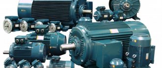
Inductors have a wide range of applications ranging from large inductors such as power supply chokes that, in combination with filter capacitors, eliminate residual noise and other oscillations in the power supply output, to as small inductors as those found inside integrated circuits.
Two (or more) inductors, which are connected by a single magnetic flux, form a transformer, which is the main component of circuits operating with an electrical power supply network. Transformer efficiency increases with increasing voltage frequency.
For this reason, aircraft use AC voltage with a frequency of 400 hertz instead of the usual 50 or 60 hertz, which in turn allows for significant savings in the mass of transformers used in the aircraft power supply.
Inductors are also used as energy storage devices in switching voltage stabilizers, in high-voltage electrical power transmission systems to deliberately reduce system voltage or limit short-circuit current.