Loop Inductance - Theory
Inductance is an idealized element whose properties are similar to an inductive coil, in which the energy of a magnetic field is accumulated.
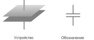
Symbol of inductance and positive directions of current, EMF of self-induction and voltage:
If a current is passed through a conductor, a magnetic flux Φ is created around it. The total magnetic flux (clutch flux) of the inductor is equal to Ψ= w×Φ, where Φ is the magnetic flux created by one turn; w is the number of turns.
By definition, self-inductance (or simply inductance) is equal to the proportionality coefficient between flux linkage and coil current L=Ψ/i.
Inductance is measured in Henry 1 H = 1 Wb / 1 A. The symbol L used to denote inductance was adopted in honor of Heinrich Friedrich Emil Lenz. The unit of inductance is named after Joseph Henry. The term inductance itself was coined by Oliver Heaviside in February 1886.
The coupling flux of the inductor is Ψ=L×i.
In accordance with the law of electromagnetic induction, when the magnetic flux changes in the coil, a self-inductive emf eL=-dΨ/dt is induced. The “-” sign is placed because the EMF has such a direction that the current it generates with its magnetic field prevents the change in the magnetic flux that causes this EMF.
The voltage across the inductance balances the EMF and can be written as uL=-eL=dΨ/dt=L×di/dt.
The instantaneous power entering the inductor is equal to p=uL×i=L×i×di/dt.
The energy stored in the inductor is wM=∫(0^t)ptd=∫(0^t)L×i×dt×di/dt=(L×i²)/2.
Mutual inductance characterizes the property of one element with current i1 to create a magnetic field that partially meshes with the turns w2 of another element.
The coefficient of mutual inductance is determined by the formula M=Ψ12/i2=Ψ21/i1, where Ψ12 is the coupling flux of the first circuit caused by the current of the second circuit (similar to Ψ21). Measured in Gn.
Mutual inductance and its calculation
For two circuits having w1 and w2 turns with currents I1 and I2 (Fig. 1.17), the flux of the first circuit, determined by the current of this circuit, the self-induction flux Ф1l, can be decomposed into the leakage flux Ф1s, penetrating only this circuit, and the mutual induction flux Ф1m, also penetrating the second circuit:
The flux linkage corresponding to flow F11 (provided that this flow penetrates all turns of the primary circuit is equal to
and leakage flux linkage
Similarly for the second circuit
The flux linkage of the second circuit, determined by the current of the first,
and the flux linkage of the first circuit, determined by the current of the second,
It can be shown that
The value M is called mutual inductance and is determined by the configuration of the circuits, their relative position and the magnetic permeability of the medium. Mutual inductance is also measured in henry (H). The total flow passing through the first circuit is
Total primary circuit flux linkage
and accordingly for the second circuit
In these algebraic sums, the first term is always positive, and the sign before the second term is determined by the direction of the currents in the circuits; a positive sign corresponds to the case when the directions of flows Ф1м and Ф2м coincide (see Fig. 1.17). From the above it is clear that
Thus, mutual inductance and inductances always satisfy the inequality
and the coupling coefficient of two circuits used in technical calculations
Similarly, in a system of many loops, the flux linkage of the loop is determined by the currents of all loops:
where Lq is the inductance of the qth circuit, Mqp = Мрq is the mutual inductance of the qth and pth circuits. The general technique for calculating the mutual inductance of circuits is to find the flux linkage that penetrates the circuit q, but created by the current of the pth circuit, and divide it by this current.
Electromagnetic induction
Electromagnetic induction is the phenomenon of the occurrence of current in a closed conducting circuit when the magnetic flux passing through it changes.
The phenomenon of electromagnetic induction was discovered by Michael Faraday through a series of experiments.
Experience once. Two coils were wound on one non-conducting base in such a way that the turns of one coil were located between the turns of the second. The turns of the first coil were closed to a galvanometer, and the second were connected to a current source.
When the key was closed and current flowed through the second coil, a current pulse arose in the first. When the switch was opened, a current pulse was also observed, but the current through the galvanometer flowed in the opposite direction.
Experience two. The first coil was connected to a current source, and the second to a galvanometer. In this case, the second coil moved relative to the first. As the coil approached or moved away, the current was recorded.
Experience three. The coil was connected to a galvanometer, and the magnet was moved relative to the coil.
Here's what these experiments showed:
- Induction current occurs only when the lines of magnetic induction change.
- The direction of the current differs when the number of lines increases and when they decrease.
- The strength of the induction current depends on the rate of change of the magnetic flux. In this case, both the field itself can change and the circuit can move in a non-uniform magnetic field.
Why does induced current occur?
Current in a circuit can exist when external forces act on free charges. The work done by these forces to move a single positive charge along a closed loop is equal to electromotive force (EMF).
This means that when the number of magnetic lines through the surface limited by the contour changes, an emf appears in it, which is called the induced emf.
Introduction
If someone came up with the idea of conducting a survey of the world's population on the topic “What do you know about inductance?”, the overwhelming number of respondents would simply shrug their shoulders. But this is the second most numerous technical element, after transistors, on which modern civilization is based! Detective fans, remembering that in their youth they read Sir Arthur Conan Doyle’s exciting stories about the adventures of the famous detective Sherlock Holmes, will, with varying degrees of confidence, mutter something about the method that the above-mentioned detective used. At the same time, implying the method of deduction, which, along with the method of induction, is the main method of knowledge in Western philosophy of the New Age.
With the induction method, individual facts, principles are studied and general theoretical concepts are formed based on the results obtained (from particular to general). The deduction method, on the contrary, involves research from general principles and laws, when the provisions of the theory are distributed into individual phenomena.
It should be noted that induction, in the sense of method, does not have any direct relation to inductance, they simply have a common Latin root inductio
- guidance, motivation - and mean completely different concepts.
Only a small part of those surveyed from among the exact sciences - professional physicists, electrical engineers, radio engineers and students in these fields - will be able to give a clear answer to this question, and some of them are ready to give an entire lecture on this topic right away.
Definition of inductance
In physics, inductance, or the coefficient of self-induction, is defined as the coefficient of proportionality L between the magnetic flux Ф around a current-carrying conductor and the current I generating it, or - in a more strict formulation - this is the coefficient of proportionality between the electric current flowing in any closed circuit and the magnetic flux created by this current:
Ф = L·I
or
L = Ф/I
To understand the physical role of the inductor in electrical circuits, one can use the analogy of the formula for the energy stored in it when current I flows with the formula for the mechanical kinetic energy of the body.
For a given current I, inductance L determines the energy of the magnetic field W created by this current I:
WI
= 1/2
L
I
2
Similarly, the mechanical kinetic energy of a body is determined by the mass of the body m and its speed V:
Wk
= 1/2 ·
m
·
V
2
That is, inductance, like mass, does not allow the energy of the magnetic field to instantly increase, just as mass does not allow this to happen with the kinetic energy of the body.
Let's study the behavior of current in inductance:
Rice. 1. Electrical diagram of the experiment
Rice. 2. Physical implementation of the experiment
Rice. 3. Oscillogram of current through inductance. The yellow oscillogram is the output of the signal generator, the blue one is the signal at the resistor.
Due to the inertia of the inductance, the fronts of the input voltage are delayed. In automation and radio engineering, such a circuit is called an integrating circuit, and is used to perform the mathematical operation of integration.
Let's study the voltage on the inductor:
Rice. 4. Electrical diagram of the experiment
Rice. 6. Voltage oscillogram across the inductance (blue)
At the moments of applying and removing voltage, due to the self-inductive emf inherent in the inductance coils, voltage surges occur. Such a circuit in automation and radio engineering is called differentiating, and is used in automation to correct processes in a controlled object that are fast in nature.
Rice. 5. By and large, in all electric current generators of any type, as well as in electric motors, their windings are inductor coils.
How to find loop inductance
The formula, which is the simplest for finding the value, is the following:
- L=F:I,
where F is the magnetic flux, I is the current in the circuit.
Self-inductive emf can be expressed through inductance:
- Ei = -L x dI : dt.
The formula suggests a conclusion about the numerical equality of induction with EMF, which occurs in the circuit when the current changes by one ammeter in one second.
Variable inductance makes it possible to find the energy of the magnetic field:
- W = L I2 : 2.
What is inductance
This term denotes the relationship that is established between the current strength in the conductor ( I ) and the created magnetic flux (F):
L = Ф/ I.
Given the basic definition, it is not difficult to understand the dependence of inductance on the properties of the environment, which influences the distribution of power lines. The dimensions and configuration of the conductive element have a certain significance.
Inductance is similar to mechanical inertia. Only in this case we are talking about actions with electrical quantities. This coefficient characterizes the ability of the component in question to resist changes in the current passing through it.
Necessary formulas for calculations
To find the inductance of the solenoid, the following formula is applied:
- L= µ0n2V,
where µ0 shows the magnetic permeability of the vacuum, n is the number of turns, V is the volume of the solenoid.
You can also calculate the inductance of the solenoid using another formula:
- L = µ0N2S : l,
It will be interesting➡ What is active power?
where S is the cross-sectional area and l is the length of the solenoid.
To find the inductance of the solenoid, any formula is used that is suitable for solving the given problem.
Designation and units of measurement
Current resistance: formula
In honor of Lenz, the unit of inductance was designated by the symbol "L". Expressed as Henry, abbreviated as Gn (in English literature N), in honor of the famous American physicist.
Joseph Henry
If, with a current change of one ampere for every second, the self-inductive emf is 1 volt, then the inductance of the circuit will be measured in 1 henry.
How can inductance be designated in other systems:
- In the SGS system, SGSM - in centimeters. To distinguish it from the unit of length, it is designated abhenry;
- In the SGSE system - in StatHenry.
Definition of inductance
Measuring the inductance of the coil can be carried out in laboratory conditions. The SI unit of inductance is 1 Henry - it is measured in a circuit with a magnetic flux of 1 Wb, and the current in the circuit is 1 Ampere. In the Gaussian system, the inductance is 1 H = 10⁹ cm.
In order to determine it, you need to measure the effective value of the alternating current and its frequency, as well as the voltage on the coil and its active resistance:
- R is the ohmic resistance of the coil.
- F is the frequency of alternating current.
- U is voltage.
- I is the current strength.
Properties
Has the following properties:
- Depends on the number of turns of the circuit, its geometric dimensions and the magnetic properties of the core;
- Cannot be negative;
- Based on the definition, the rate of change of current in the circuit is limited by the value of its inductance;
- As the frequency of the current increases, the reactance of the coil increases;
- It has the property of storing energy - when the current is turned off, the stored energy tends to compensate for the drop in current.
Inductance and capacitor
The current-carrying elements of the device are capable of creating its own inductance. These are such structural parts as masonry, connecting busbars, down conductors, terminals and fuses. It is possible to create additional capacitor inductance by connecting busbars. The operating mode of an electrical circuit depends on inductance, capacitance and active resistance. The formula for calculating the inductance that occurs when approaching the resonant frequency is as follows:
- Ce = C: (1 – 4Π2f2LC),
where Ce determines the effective capacitance of the capacitor, C indicates the actual capacitance, f is the frequency, L is the inductance.
The inductance value must always be taken into account when working with power capacitors. For pulse capacitors, the most important value is the self-inductance. Their discharge falls on the inductive circuit and has two types - aperiodic and oscillatory.
The inductance in a capacitor depends on the connection diagram of the elements in it. For example, when sections and buses are connected in parallel, this value is equal to the sum of the inductances of the package of main buses and terminals. To find this kind of inductance, the formula is as follows:
- Lk = Lp + Lm + Lb,
where Lk shows the inductance of the device, Lp of the package, Lm of the main buses, and Lb of the inductance of the terminals.
If, in a parallel connection, the bus current varies along its length, then the equivalent inductance is determined as follows:
- Lk = Lc : n + µ0 l x d : (3b) + Lb,
where l is the length of the tires, b is its width, and d is the distance between the tires.
To reduce the inductance of the device, it is necessary to arrange the current-carrying parts of the capacitor so that their magnetic fields are mutually compensated. In other words, current-carrying parts with the same current movement must be removed from each other as far as possible, and those with the opposite direction should be brought closer together. By combining down conductors with a decrease in dielectric thickness, the inductance of the section can be reduced. This can also be achieved by dividing one section with a large volume into several with smaller capacity.
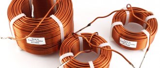
"Spool of thread"
An inductor is an insulated copper wire wound on a solid base. As for insulation, the choice of material is wide - varnish, wire insulation, and fabric. The magnitude of the magnetic flux depends on the area of the cylinder. If you increase the current in the coil, the magnetic field will become larger and vice versa.
If you apply an electric current to a coil, a voltage appears in it opposite to the current voltage, but it suddenly disappears. This kind of voltage is called electromotive force of self-induction. At the moment the voltage is turned on to the coil, the current changes its value from 0 to a certain number. The voltage at this moment also changes its value, according to Ohm’s law:
- I = U : R,
where I characterizes the current strength, U indicates the voltage, R is the coil resistance.
Another special feature of the coil is the following fact: if you open the “coil - current source” circuit, the EMF will be added to the voltage. The current will also initially increase and then decline. This implies the first law of commutation, which states that the current strength in the inductor does not change instantly.
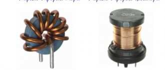
The coil can be divided into two types:
- With magnetic tip. The material of the heart is ferrites and iron. The cores serve to increase inductance.
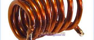
- With non-magnetic. Used in cases where the inductance is no more than five milliHenry.
The devices differ in appearance and internal structure. Depending on these parameters, the inductance of the coil is determined. The formula is different in each case. For example, for a single-layer coil the inductance will be equal to:
- L = 10µ0ΠN2R2 : 9R + 10l.
But for a multilayer one there is another formula:
- L= µ0N2R2 :2Π(6R + 9l + 10w).
Main conclusions related to the operation of coils:
- On a cylindrical ferrite, the largest inductance occurs in the middle.
- To obtain maximum inductance, it is necessary to wind the turns closely on the coil.
- The smaller the number of turns, the smaller the inductance.
- In a toroidal core, the distance between the turns does not play the role of the coil.
- The inductance value depends on the “turns squared”.
- If inductances are connected in series, then their total value is equal to the sum of the inductances.
- When connecting in parallel, you need to ensure that the inductances are spaced apart on the board. Otherwise, their readings will be incorrect due to the mutual influence of magnetic fields.
It will be interesting➡ What is the selectivity of circuit breakers + principles for calculating selectivity
Series and parallel connection of inductors
Inductors can be connected in series or in parallel, resulting in a set with new characteristics.
Parallel connection
When the coils are connected in parallel, the voltages on all elements are equal, and the currents (variables) are distributed in inverse proportion to the inductances of the elements.
- U=U1=U2=U3;
- I=I1+I2+I3.
The total inductance of the circuit is defined as 1/L=1/L1+1/L2+1/L3. The formula is valid for any number of elements, and for two coils it is simplified to the form L=L1*L2/(L1+L2). Obviously, the final inductance is less than the inductance of the element with the smallest value
Serial connection
With this type of connection, the same current flows through a circuit made up of coils, and the voltage (alternating!) on each component of the circuit is distributed in proportion to the inductance of each element:
- U=U1+U2+U3;
- I=I1=I2=I3.
The total inductance is equal to the sum of all inductances, and will be greater than the inductance of the element with the largest value. Therefore, such a connection is used when it is necessary to increase the inductance.
Important! When connecting coils into a series or parallel battery, the calculation formulas are correct only for cases where the mutual influence of the magnetic fields of the elements on each other is excluded (by shielding, large distances, etc.). If an influence exists, then the overall value of the inductance will depend on the relative position of the coils.
Application of inductors
Inductors are widely used in analog and signal processing circuits. They combine with capacitors and other radio components to form special circuits that can amplify or filter signals of a specific frequency.
Inductors have a wide range of applications ranging from large inductors such as power supply chokes that, in combination with filter capacitors, eliminate residual noise and other oscillations in the power supply output, to as small inductors as those found inside integrated circuits.
Two (or more) inductors, which are connected by a single magnetic flux, form a transformer, which is the main component of circuits operating with an electrical power supply network. Transformer efficiency increases with increasing voltage frequency.
For this reason, aircraft use AC voltage with a frequency of 400 hertz instead of the usual 50 or 60 hertz, which in turn allows for significant savings in the mass of transformers used in the aircraft power supply.
Inductors are also used as energy storage devices in switching voltage stabilizers, in high-voltage electrical power transmission systems to deliberately reduce system voltage or limit short-circuit current.
General information
In order to understand what the inductance of the coil depends on, it is necessary to study in detail all the information about this physical quantity. The first step is to consider the accepted international designation of the parameter, its purpose, characteristics and units of measurement.
The very concept of inductance was proposed by the famous English physicist Oliver Heaviside, who studied it. This scientist gave the world other well-known terms - electrical conductivity, magnetic permeability and resistance, as well as EMF (electromotive force).
The first letter of the surname of another famous physicist, Emilia Lenza, was taken as a designation for inductance in formulas and when carrying out calculations. Today, the symbol L continues to be used when referring to this parameter.
The outstanding American physicist Joseph Henry was the first to discover the phenomenon of inductance. In his honor, physicists named the unit of measurement in the international SI, which is most often used in calculations. In other systems (Gaussian and SGS), inductance is measured in centimeters. To simplify the calculations, a relationship was adopted in which 1 cm equals 1 nanohenry. The very rarely used SGSE system leaves the self-induction coefficient without any units of measurement or uses the stathenry value. It depends on several parameters and is approximately equal to 89875520000 henry.
Among the main properties of inductance are:
- The parameter value can never be less than zero.
- The indicator depends only on the magnetic properties of the coil core, as well as on the geometric dimensions of the circuit.
Calculation methods
There are several basic ways to determine the inductance of a coil. All formulas that will be used in the calculations can be easily found in reference books or on the Internet. The whole calculation process is quite simple and will not be difficult for people with basic mathematical and physical knowledge.
Through current
This calculation is considered the simplest way to determine the inductance of a coil. The formula through current follows from the term itself. What is the inductance of the coil can be determined by the formula: L=Ф/I, where:
- L - circuit inductance (in Henry);
- F is the magnitude of the magnetic flux, measured in webers;
- I is the current strength in the coil (in amperes).
This formula is only suitable for a single-turn circuit. If the coil consists of several turns, then instead of the magnetic flux value, the total flux (total value) is used. When the same magnetic flux passes through all the turns, then to determine the total value it is enough to multiply the value of one of them by the total number.
Finite Length Solenoid
The solenoid is a thin long coil, where the thickness of the winding is significantly less than the diameter. In this case, calculations are carried out using the same formula as through current strength, only the magnitude of the magnetic flux will be determined as follows: Ф=µ0NS/l, where:
- µ0 is the magnetic permeability of the medium, determined from lookup tables (for air, which is taken by default in most calculations, it is equal to 0.00000126 henry/meter);
- N is the number of turns in the coil;
- S is the cross-sectional area of the coil, measured in square meters;
- l is the length of the solenoid in meters.
The self-induction coefficient of the solenoid can also be calculated based on the method for determining the energy of the magnetic flux of the field. This is a simpler option, but it requires some quantities. The formula for finding inductance is L=2W/I 2, where:
- W is the magnetic flux energy, measured in joules;
- I is the current strength in amperes.
Toroidal core coil
In most cases, the toroidal coil is wound on a core made of a material with high magnetic permeability. In this case, to calculate the inductance, you can use the formula for a straight solenoid of infinite length. It has the following form: L=N µ0 µS/2 πr, where:
- N is the number of coil turns;
- µ—relative magnetic permeability;
- µ0—magnetic constant;
- S is the cross-sectional area of the core;
- π is a mathematical constant equal to 3.14;
- r is the average radius of the torus.
It will be interesting➡ Circuit breakers
Long conductor
Most of these quasi-linear conductors have a circular cross-section. In this case, the value of the self-induction coefficient will be determined by the standard formula for approximate calculations: L= µ0l (µelnl/r+ µi/4)/2 π. The following notations are used here:
- l is the length of the conductor in meters;
- r is the radius of the wire cross-section, measured in meters;
- µ0—magnetic constant;
- µi is the relative magnetic permeability characteristic of the material from which the conductor is made;
- µe is the relative magnetic permeability of the external environment (most often the value for vacuum is taken to be 1);
- π—pi number;
- ln is the notation for logarithm.
Influence of the number of turns and winding method
Conductor inductance
An inductor is a spiral made of conductive material. The operating parameters of the products will depend on the design features. Inductance is increased:
- a large number of turns per unit length;
- enlargement of the cross section;
- installation in the central part of the core with ferromagnetic characteristics.
What does the inductance of the coil depend on, examples of typical solutions
Single-turn inductance and coil inductance
To calculate an elementary structure, the converted first formula is suitable:
Ф = L * I.
If a coil is considered, this expression is transformed into the total expression of the magnetic fluxes (Ψ) generated by the individual turns:
Ψ = n * F.
The same way:
Ln = L1 * n.
In fact, for accurate calculations, differences in force lines in the central part and at the edges of the structure are taken into account. More complex expressions are used for correction.
Solenoid inductance
A sufficiently long electric coil forms parallel lines of force inside. To create a uniform distribution of energy, it is necessary to use a conductor with a thickness much smaller compared to the cross-sectional diameter. Of course, it is necessary to set the same distance between the individual turns.
This design is called a solenoid. The magnetic flux density ( B ) in the central working part will depend in direct proportion to the length ( l ) and the following parameters:
- number of turns (N);
- current (i);
- winding density (n – number of circuits per unit length);
- cross-sectional area (S);
- volume (V = S * l).
Below are the basic formulas for calculations in the absence of a core, taking into account the magnetic constant ( m 0 ≈ 1.257 * 10-6 H/m):
- B = m0 * N * (i/l) = m0 * n * I;
- Ψ = m0 * N2 * (I * S/l) = m0 * n2 * i *V;
- L = m0 * N2 * (S/l) = m0 * n2 * V.
Inductance of a toroidal coil (ring-core coil)
To calculate the induction of a coil with a core, a correction factor “m” is added to the above formulas. Taking into account the special shape of the product, the following changes must be made:
L = N2 * ((m0 * m * S)/2π * rL), or L = N2 * ((m0 * m * h)/2π) * ln(R/r),
Where:
- 2π * rL – length of the working element with an average radius rL;
- R (r) and h are the outer (inner) radius and height of the torus, respectively.
The coefficient “m” takes into account the relative magnetic permeability of a certain material to the value for a neutral environment (vacuum). If m is much greater than unity, it is possible to ignore the field distortions created by a thick conductor.
Graphical output of the formula
It is possible to obtain the written formula using the graphical method. To do this, let us display on a graph the dependence of the magnetic flux Φ(I) on the current I (Fig. 1.21.2). The total amount of heat released, which is equal to the initial energy reserve of the magnetic field, is determined as the area of the resulting figure in Fig. 1.21.2 triangles:
Figure 1.21.2. Calculation of magnetic field energy.
As a result, the formula for the energy Wm of the magnetic field of a coil with inductance L, created by current I, will be written as the formula:
Wм=ΦI2=LI22=Φ22L
Let's use the expression we got for the coil energy to a long solenoid with a magnetic core. Applying the above formulas for the self-induction coefficient Lμ of the solenoid and for the magnetic field B created by the current I, we obtain the entry:
Wм=μ0·μ·n2·I22V=B22μ0·μV
In this formula, V is the volume of the solenoid. The resulting expression demonstrates to us that magnetic energy is not localized in the turns of the coil through which the current passes, but is distributed throughout the entire volume in which the magnetic field arose.
Definition 4
Volumetric magnetic energy density is a physical quantity that is equal to the magnetic field energy per unit volume: Wм=B22μ·μ.
At one time, Maxwell demonstrated that the indicated formula (in our case, derived for a long solenoid) is correct for any magnetic fields.
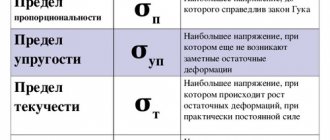
Linear and nonlinear inductors
For linear materials, the magnetic permeability µ does not depend on the field strength and the characteristic for them is depicted by a straight line (Fig. 1.18, a). Magnetic permeability is proportional to the tangent of the angle a of the slope of this straight line:
where k is the scale factor.
Nonlinear materials include ferromagnets and iron, nickel, cobalt and gadolinium. The first three elements are important in electrical engineering, mainly in the form of alloys. In nonlinear materials, the magnetic permeability is very high and depends on the field strength.
Similar to nonlinear dielectrics, the static magnetic permeability can be determined from the initial magnetization curve B (H) (Fig. 1.18, b)
and differential, and with rapid field changes - dynamic magnetic permeability
In Fig. 1.18, b these permeabilities are presented as a function of field strength. The maximum values of magnetic permeability in very pure iron and in some alloys, for example in permalloy (an alloy of iron and nickel with various additives), are hundreds of thousands of times higher than the magnetic constant equal to
magnetic permeability of vacuum.
In alternating magnetic fields in ferromagnets, the phenomenon of magnetic hysteresis occurs (Fig. 1.19), which consists in the discrepancy between the B (H) curve as the field strength increases and the curve as the field decreases.
The curve connecting the tops of the hysteresis loops is called the main magnetization curve and practically coincides with the initial magnetization curve. Ferromagnetic properties depend on temperature and appear only in a certain temperature range.
To calculate the inductance, the main one is the dependence of the flux linkage ψ on the current I, called the Weber-ampere characteristic.
Depending on the core material, the toroids will also be linear or nonlinear in terms of their weberampere characteristics. A nonlinear toroid is considered as an example.
For a toroid, the webampere characteristics ψ (I) on the appropriate scale coincide with curves B (H); therefore the straight line and curves in Fig. 1.18 a and b also correspond to weberampere characteristics at the values indicated in parentheses.
For nonlinear toroids, the concepts of static inductance are introduced
and differential as well as dynamic inductance
which are functions of current (see Fig. 1.18, b); for linear toroids these inductances are the same.
Similar to inductances in nonlinear circuit systems, static mutual inductance is introduced
and differential, mutual inductance, as well as dynamic
About inductance in simple words
Inductance is a physical quantity that was introduced to evaluate the ability of an electrical conductor to resist current. Those. inductance, or as it is also called, the self-inductance coefficient, shows the dependence of Ɛ on the properties of the conductor and on the magnetic permeability of the environment in which it is located. The unit of measurement is henry (H).
If we consider the value using an inductor as an example, we can understand that its performance will vary depending on the number of turns of the coil, as well as its size and shape. The greater the number of turns, the greater the inductance. This value will also be increased if a core is placed inside the coil, since the relative magnetic permeability of the medium in which the conductor is located will change. This relationship can be seen in the diagram.
If you look at the formula for the dependence of EMF on inductance, you can understand that the greater the value, the more noticeable the electromotive force will be, which indicates their direct proportionality. Following from this, we can conclude that inductance acts as a kind of “storage” of energy, which opens at the moment the current changes.
Ɛ=- L(dI/dt), where:
- Ɛ – self-induced emf;
- L-inductance;
- I – current strength;
- t – time.
In this case, L is equal to the magnetic field (Ф) divided by the current strength (I).
Core material
What does the resistance of a conductor depend on?
As in the previous example, to calculate the induction of a coil with a core, the relative magnetic permeability multiplier “ m ” :
L = m0 * m * N2 * (S/l) = m0 * m * n2 * V.
Using this coefficient, the ferromagnetic properties of a certain material are taken into account.
If, for example, we take an endless (very long) straight wire with a circular cross-section, then it will have a certain inductance:
L = (m0/2π) * l *(mc * ln(l/r) +1/4m,
Where:
- mc – magnetic permeability (relative) of the medium;
- r is the radius, which is much less than the length (l) of the conductor.
However, simple dependencies only operate up to a certain frequency. From a certain level, short waves begin to propagate in the surface part of the conductors (skin effect). Additionally, it is necessary to take into account the influence of vortex components that screen radiation and change the force parameters of the field.
Modern magnetic materials
The coil will work exactly as designed if all functional components of the design are correctly selected. As shown above, core parameters are essential. Important features of the relevant materials are noted below:
- Steel with low impurity content is inexpensive. It is recommended for use in DC circuits, since losses increase significantly with increasing frequency.
- Silicon is added to special grades (transformer steel). To reduce the harmful effects of surface effects, the core is assembled from plates. However, such solutions should not be used at frequencies above 1 kHz.
- Alloys made of iron and nickel are characterized by increased magnetic permeability. Operating range – up to 80-120 kHz.
- Powder materials are created with a layer of dielectric on the surfaces of individual microscopic granules. They are well suited for working with high-frequency signals, but do not have high magnetic permeability.
- Ferrites are materials created on the basis of ceramic components. They have good technical characteristics and low losses. It is necessary to take into account the significant dependence on temperature, as well as the deterioration of operating parameters during long-term operation.
Measuring the inductance of a coil made of copper wire on a ferrite core