Alphanumeric marking of resistors
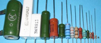
The simplest in terms of evaluation is the Soviet resistor, its power rating is marked directly on the case with the marking MLT-1 and so on, where the unit of measurement is power, and MLT is the type of resistors most popular in Soviet times, and this abbreviation means that the resistor is M - metal film, L-varnished, T-heat-resistant. The power of such resistors depends on their size; the larger the resistor, the more power it can dissipate. These resistors are already an endangered species; they can be found in old electronic equipment.
, the unit of measurement of resistance, like others, is Ohms, they are designated as R and E. The exact power size is indicated by the additional letter “ K ” - kilo-ohms or the letter “ M ” - mega-ohms; the measurement system here is quite simple. For example: 33E is 33 Ohms, and 47K is 47 kOhms, respectively, 1M2 is 1.2 Megaohms and so on.
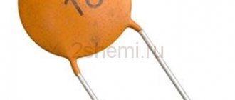
If there is only a number without a letter, then they mean that this resistance is in Ohms, and the tolerance with this designation is 20%. For example, if the number 10 is written, then you have a resistor with a resistance of 10 ohms, and the tolerance is 20%.
Examples of alphanumeric markings of resistors
3E9I or 3R9 means that the resistance is 3.9 Ohms, tolerance 5%
2K2I means that the resistance is 2.2 kOhm, tolerance 5%
5K1S means that the resistance is 5.1 kOhm, tolerance is 10%
Code marking of domestic resistors
In accordance with GOST 11076-69 and the requirements of Publications 62 and 115-2 IEC, the first 3 or 4 characters carry information about the resistor value, determined by the base value from the EZ...E192 series, and the multiplier. The last character carries information about the admission, i.e. resistor accuracy class. The requirements of GOST and IEC practically coincide with another standard BS1852 (British Standard).
Rice. 5 Code marking.
In addition to the line defining the rating and tolerance of the resistor, additional information about the type of resistor, its rated power and date of manufacture can be included.
For example:
Rice. 6 Additional information about resistor type.
Color coding of resistors
Color coding has made the marking process a little easier on a mass production scale, but has also confused some hams, but it's actually quite simple.
The starting point of the report is usually considered to be a gold stripe or a silver one - this is the initial link, and it is not counted; it is necessary to rotate it and orient it so that the colored stripes start on the left side.
Next it reads the number by stripes:
- 0-black;
- 1-brown;
- 2-Red;
- 3-Orange;
- 4-Yellow;
- 5-Green;
- 6-Blue;
- 7-Purple;
- 8-Grey;
- 9-White.
The third bar in the barcode has a slightly different meaning - it measures the number of zeros that need to be added to the resulting value. Therefore, black is 0, cinnamon is 1 zero (0), red is 2 zeros (00), and so on.
To simplify your calculations, you can use a program on your computer called Resistor 2.2 (link to download the program in the attachment). It will simplify the calculations and automatically show the power of the resistor when all strips are entered. Or use the resistor color coding calculator directly online.
Subtleties of marking
Resistors, especially low-power ones, are small parts; a 0.125W resistor has a length of several millimeters and a diameter of the order of a millimeter. It is difficult to read the denomination with a decimal point on such a part, therefore, when indicating the denomination, instead of the decimal point, write the letter corresponding to the units of measurement (K - for kilo-ohms, M - for mega-ohms, E or R for ohm units). In addition, any denomination is displayed with a maximum of three symbols. For example, 4K7 denotes a resistor with a resistance of 4.7 kOhm, 1R0 - 1 Ohm, M12 - 120 kOhm (0.12 MOhm), etc. However, in this form it is difficult to apply values to small resistors, and they are marked with colored stripes.
For resistors with an accuracy of 20%, markings with three stripes are used, for resistors with an accuracy of 10% and 5%, markings with four stripes are used, for more accurate resistors with five or six stripes. The first two stripes always indicate the first two digits of the denomination. If there are 3 or 4 bars, the third bar represents the decimal factor, that is, the power of ten that is multiplied by the two-digit number indicated by the first two bars. If there are 4 stripes, the last one indicates the accuracy of the resistor. If there are 5 stripes, the third means the third sign of resistance, the fourth is the decimal multiplier, the fifth is the accuracy.
The sixth strip, if present, indicates the temperature coefficient of resistance (TCR). If this strip is 1.5 times wider than the others, then it indicates the reliability of the resistor (% failures per 1000 hours of operation). It should be noted that sometimes there are resistors with 5 bands, but standard (5 or 10%) accuracy. In this case, the first two stripes set the first digits of the denomination, the third - the multiplier, the fourth - the accuracy, and the fifth - the temperature coefficient.
Marking of SMD resistors
SMD marking is a little more complicated; the dimensions of SMD resistors do not allow color rings to be applied to them or the value to be written. Therefore, they are marked with 3 or 4 numbers, except for resistors of size 0402 . The values of resistors of type 0402 can be found in the table. The rest have the following marking order.
Resistors with a tolerance of up to 10% are marked with 3 digits, where the first 2 digits are the resistor value, and the last one indicates the decimal value.
Example of SMD resistor markings:
3 Character Resistor
A resistor with the numbers 222 means 22 * 102 = 2200 Ohms or in other words 2.2 kOhms.
4 Character Resistor
Resistors with 4 characters have a tolerance of 1%, we calculate in the same way: 4422 is 442 * 2 * 102 = 44.2 kOhm
There are also smd resistors without markings, such resistors have a resistance of 0, they are needed simply to fill the empty space on the board, they are also called zero resistors.
The use of codes is currently the most popular way of marking SMD resistors, based on tabular codes for each indicator.
Trimmer resistors
A trim resistor (potentiometer) is a variable resistor that is usually used in control and measuring instruments to fine-tune the operating mode or correct the metrological characteristics of measuring channels. Typically, the trimmer is used once - during the setup procedure, or occasionally - from time to time.
After adjustment manipulations, the adjusting screw is secured (for example, painted over) so that during further operation of the product its position does not move due to random mechanical influences (vibrations, shocks). The number of adjustments for such resistors is limited to several tens of full turns.
Trimmer resistors (potentiometers), as a rule, are installed inside the device housing. They have different design solutions.
Just like variables, tuning resistors can be made of wire or based on a wear-resistant sputtered conductor. There are single-turn (shown in Figures 1.12a - 1.12d) and multi-turn (shown in Figures 1.12e - 1.12k) potentiometers. Potentiometers can be relatively powerful with an adjusting element, which can be placed on the outside of the device (shown in Figures 1.12l, 1.12m, 1.12n).
As an example, consider the characteristics of a typical multi-turn potentiometer type Bourns 3296W-1-472LF (shown in Figure 1.13)
As an example, consider the characteristics of a typical multi-turn potentiometer type Bourns 3296W-1-472LF (shown in Figure 1.13)
Comparative characteristics of alternative types of trimming resistors are presented in Table 1.6, designations of trimming resistors are shown in Figure 1.15.
Table 1.6 - Comparative characteristics of tuning multi-turn resistors with a nominal value of 330 Ohms
Table of SMD resistor codes and their values
| Code smd | Meaning | Code smd | Meaning | Code smd | Meaning | Code smd | Meaning |
| R10 | 0.1 Ohm | 1R0 | 1 ohm | 100 | 10 ohm | 101 | 100 Ohm |
| R11 | 0.11 Ohm | 1R1 | 1.1 Ohm | 110 | 11 ohm | 111 | 110 Ohm |
| R12 | 0.12 Ohm | 1R2 | 1.2 Ohm | 120 | 12 ohm | 121 | 120 Ohm |
| R13 | 0.13 Ohm | 1R3 | 1.3 Ohm | 130 | 13 ohm | 131 | 130 Ohm |
| R15 | 0.15 Ohm | 1R5 | 1.5 Ohm | 150 | 15 ohm | 151 | 150 Ohm |
| R16 | 0.16 Ohm | 1R6 | 1.6 Ohm | 160 | 16 ohm | 161 | 160 Ohm |
| R18 | 0.18 Ohm | 1R8 | 1.8 Ohm | 180 | 18 ohm | 181 | 180 Ohm |
| R20 | 0.2 Ohm | 2R0 | 2 ohm | 200 | 20 ohm | 201 | 200 Ohm |
| R22 | 0.22 Ohm | 2R2 | 2.2 Ohm | 220 | 22 Ohm | 221 | 220 Ohm |
| R24 | 0.24 Ohm | 2R4 | 2.4 Ohm | 240 | 24 ohm | 241 | 240 Ohm |
| R27 | 0.27 Ohm | 2R7 | 2.7 Ohm | 270 | 27 Ohm | 271 | 270 Ohm |
| R30 | 0.3 ohm | 3R0 | 3 ohm | 300 | 30 ohm | 301 | 300 Ohm |
| R33 | 0.33 Ohm | 3R3 | 3.3 Ohm | 330 | 33 Ohm | 331 | 330 Ohm |
| R36 | 0.36 Ohm | 3R6 | 3.6 Ohm | 360 | 36 Ohm | 361 | 360 Ohm |
| R39 | 0.39 Ohm | 3R9 | 3.9 Ohm | 390 | 39 Ohm | 391 | 390 Ohm |
| R43 | 0.43 Ohm | 4R3 | 4.3 Ohm | 430 | 43 Ohm | 431 | 430 Ohm |
| R47 | 0.47 Ohm | 4R7 | 4.7 Ohm | 470 | 47 Ohm | 471 | 470 Ohm |
| R51 | 0.51 Ohm | 5R1 | 5.1 Ohm | 510 | 51 Ohm | 511 | 510 Ohm |
| R56 | 0.56 Ohm | 5R6 | 5.6 Ohm | 560 | 56 Ohm | 561 | 560 Ohm |
| R62 | 0.62 Ohm | 6R2 | 6.2 Ohm | 620 | 62 Ohm | 621 | 620 Ohm |
| R68 | 0.68 Ohm | 6R8 | 6.8 Ohm | 680 | 68 Ohm | 681 | 680 Ohm |
| R75 | 0.75 Ohm | 7R5 | 7.5 Ohm | 750 | 75 Ohm | 751 | 750 Ohm |
| R82 | 0.82 Ohm | 8R2 | 8.2 Ohm | 820 | 82 Ohm | 821 | 820 Ohm |
| R91 | 0.91 Ohm | 9R1 | 9.1 Ohm | 910 | 91 Ohm | 911 | 910 Ohm |
| Code smd | Meaning | Code smd | Meaning | Code smd | Meaning | Code smd | Meaning |
| 102 | 1 kOhm | 103 | 10 kOhm | 104 | 100 kOhm | 105 | 1 MOhm |
| 112 | 1.1 kOhm | 113 | 11 kOhm | 114 | 110 kOhm | 115 | 1.1 MOhm |
| 122 | 1.2 kOhm | 123 | 12 kOhm | 124 | 120 kOhm | 125 | 1.2 MOhm |
| 132 | 1.3 kOhm | 133 | 13 kOhm | 134 | 130 kOhm | 135 | 1.3 MOhm |
| 152 | 1.5 kOhm | 153 | 15 kOhm | 154 | 150 kOhm | 155 | 1.5 MOhm |
| 162 | 1.6 kOhm | 163 | 16 kOhm | 164 | 160 kOhm | 165 | 1.6 MOhm |
| 182 | 1.8 kOhm | 183 | 18 kOhm | 184 | 180 kOhm | 185 | 1.8 MOhm |
| 202 | 2 kOhm | 203 | 20 kOhm | 204 | 200 kOhm | 205 | 2 MOhm |
| 222 | 2.2 kOhm | 223 | 22 kOhm | 224 | 220 kOhm | 225 | 2.2 MOhm |
| 242 | 2.4 kOhm | 243 | 24 kOhm | 244 | 240 kOhm | 245 | 2.4 MOhm |
| 272 | 2.7 kOhm | 273 | 27 kOhm | 274 | 270 kOhm | 275 | 2.7 MOhm |
| 302 | 3 kOhm | 303 | 30 kOhm | 304 | 300 kOhm | 305 | 3 MOhm |
| 332 | 3.3 kOhm | 333 | 33 kOhm | 334 | 330 kOhm | 335 | 3.3 MOhm |
| 362 | 3.6 kOhm | 363 | 36 kOhm | 364 | 360 kOhm | 365 | 3.6 MOhm |
| 392 | 3.9 kOhm | 393 | 39 kOhm | 394 | 390 kOhm | 395 | 3.9 MOhm |
| 432 | 4.3 kOhm | 433 | 43 kOhm | 434 | 430 kOhm | 435 | 4.3 MOhm |
| 472 | 4.7 kOhm | 473 | 47 kOhm | 474 | 470 kOhm | 475 | 4.7 MOhm |
| 512 | 5.1 kOhm | 513 | 51 kOhm | 514 | 510 kOhm | 515 | 5.1 MOhm |
| 562 | 5.6 kOhm | 563 | 56 kOhm | 564 | 560 kOhm | 565 | 5.6 MOhm |
| 622 | 6.2 kOhm | 623 | 62 kOhm | 624 | 620 kOhm | 625 | 6.2 MOhm |
| 682 | 6.8 kOhm | 683 | 68 kOhm | 684 | 680 kOhm | 685 | 6.8 MOhm |
| 752 | 7.5 kOhm | 753 | 75 kOhm | 754 | 750 kOhm | 755 | 7.5 MOhm |
| 822 | 8.2 kOhm | 823 | 82 kOhm | 824 | 820 kOhm | 815 | 8.2 MOhm |
| 912 | 9.1 kOhm | 913 | 91 kOhm | 914 | 910 kOhm | 915 | 9.1 MOhm |
General universal table of values
Of course, it is extremely difficult to keep all the designations and color relationships in your head. Yes, and there is no particular need for this. But there is a universal table of color values, thanks to which the color markings of resistors can be deciphered without much difficulty.
Similar designations are accepted by most manufacturers in the world, which makes it universal for any country.
For example, you can consider a 6-band version with color rings: red, orange, yellow, green, blue, brown.
- Red—numeric value “2.”
- Orange - numeric value "3".
- Yellow—numeric value “4.”
- Green - the fourth bar indicates the multiplier; for green (according to the table) this value is 1*10⁵. Based on the table, the first three colors give the value “234”. After calculating 234*10⁵, we get 2.34 MOhm.
- Blue - determines the accuracy, which for this color is 0.25%, i.e. this is exactly the possible deviation from the initial value in either direction when the resistor is operating.
- Brown - indicates the temperature coefficient, in this case the value is 100 ppm/°C.
Marking of SMD resistors according to EIA-96
SMD resistors with greater precision and smaller dimensions have led to the creation of compact markings. The EIA-96 standard was invented . This standard is designed for resistors with a resistance tolerance of 1%.
This marking system consists of three symbols: the first two digits are the resistor value code, and the next symbol is the multiplier. We take the SMD resistor, look at the first 2 digits and find the corresponding resistance from the table, then look at the number and also look at the table by which to multiply by. It's quite simple.
02A = 200 Ohm ±1%
10S = 1 ohm ±1%
10C = 1000 ohms ±1%
Resistor marking table according to EIA-96 (value codes)
| Code | Number | Code | Number | Code | Number | Number | Number |
| 01 | 100 | 25 | 178 | 49 | 316 | 73 | 562 |
| 02 | 102 | 26 | 182 | 50 | 324 | 74 | 576 |
| 03 | 105 | 27 | 187 | 51 | 332 | 75 | 590 |
| 04 | 107 | 28 | 191 | 52 | 340 | 76 | 604 |
| 05 | 110 | 29 | 196 | 53 | 348 | 77 | 619 |
| 06 | 113 | 30 | 200 | 54 | 357 | 78 | 634 |
| 07 | 115 | 31 | 205 | 55 | 365 | 79 | 649 |
| 08 | 118 | 32 | 210 | 56 | 374 | 80 | 665 |
| 09 | 121 | 33 | 215 | 57 | 383 | 81 | 681 |
| 10 | 124 | 34 | 221 | 58 | 392 | 82 | 698 |
| 11 | 127 | 35 | 226 | 59 | 402 | 83 | 715 |
| 12 | 130 | 36 | 232 | 60 | 412 | 84 | 732 |
| 13 | 133 | 37 | 237 | 61 | 422 | 85 | 750 |
| 14 | 137 | 38 | 243 | 62 | 432 | 86 | 768 |
| 15 | 140 | 39 | 249 | 63 | 442 | 87 | 787 |
| 16 | 143 | 40 | 255 | 64 | 453 | 88 | 806 |
| 17 | 147 | 41 | 261 | 65 | 464 | 89 | 825 |
| 18 | 150 | 42 | 267 | 66 | 475 | 90 | 845 |
| 19 | 154 | 43 | 274 | 67 | 487 | 91 | 866 |
| 20 | 158 | 44 | 280 | 68 | 499 | 92 | 887 |
| 21 | 162 | 45 | 287 | 69 | 511 | 93 | 909 |
| 22 | 165 | 46 | 294 | 70 | 523 | 94 | 931 |
| 23 | 169 | 47 | 301 | 71 | 536 | 95 | 953 |
| 24 | 174 | 48 | 309 | 72 | 549 | 96 | 976 |
What is a resistor
The resistor, as an element of microcircuits and power networks, gets its name from the English word “resistor”. It, in turn, has the Latin roots “resisto”, which is literally translated into Russian as “I resist”. As its name suggests, its purpose is to resist the flow of charged electrons.
The part is classified as a passive component in an electrical circuit, where it reduces the voltage to the design level. Unlike active elements, a resistor cannot independently amplify signals. According to Ohm's law and Kirhoff's law, the voltage is reduced to values equal to the voltage values multiplied by the existing resistance.
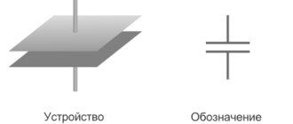
In accordance with GOST, it is depicted in the drawings as a rectangle. To indicate the power of resistors in the diagram, special markings are used in the form of lines and Arabic numerals. It helps to briefly indicate the type and characteristics of the required element.
Five strip resistors
Resistor C2-29V
Constant non-wire resistor C2-29V.
Permanent non-wire precision resistors C2-29V in isolated and non-insulated design, designed for operation in circuits of direct, alternating and pulsed currents.
Resistors S2-29V are manufactured in climatic version B. Resistors S2-29V are manufactured in accordance with the technical specifications OZHO .467.130 TU (acceptance "QTK"), OZHO .467.099 TU (acceptance "5"), OZHO .467.138 TU (acceptance "9" "). Note. The technical conditions BADC.430410.002 TU for resistors S2-29V, developed by the Severodonetsk Resistance Plant, are similar to the technical conditions OZhO.467.099 TU and were developed due to the difficulty of resolving issues with the calculator company OZHO.467.099 TU for subscriber services in connection with the collapse of the USSR.
Main dimensions of resistors C2-29V:
| Type of resistor | Dimensions, mm | Weight, g, no more | |||
| Lmax | Dmax | d | l | ||
| S2-29V-0.062 | 6,5-0,5 | 2,3-0,4 | 0,6±0,1 | 16+4 | 0,25 |
| S2-29V-0.125 | 8,0-1,6 | 3,5-0,7 | 0,3 | ||
| S2-29V-0.25 | 11-1,3 | 4,5-0,8 | 0,8±0,1 | 25±3 | 1,0 |
| S2-29V-0.5M | 11-1,3 | 4,5-0,8 | 1,0 | ||
| S2-29V-1 | 20-2,7 | 9,8-1,3 | 1,0±0,1 | 3,5 | |
| S2-29V-2 | 28-2,3 | 5,0 | |||
The symbol of the resistor S2-29V when ordering and in the design documentation must consist of the word “Resistor”, an abbreviated symbol of the resistor, rated power dissipation, full designation of the nominal resistance and permissible deviation in accordance with GOST 28883-90, group by noise level, group by temperature resistance coefficient, designation TU.
An example of a symbol for a resistor S-29V:
Resistor S2-29V - 0.125 - 110 kOhm ±1% - 1.0 - A OZHO.467.099 TU
Basic technical data of resistors S2-29V:
Rated power dissipation, rated resistance and permissible deviations of rated resistance, maximum operating voltage:
| Type of resistor | Rated power dissipation, W | Nominal resistance, Ohm | Limit operating voltage, V | |||
| direct current | alternating (rms) current | direct current | alternating (rms) current | |||
| at atmospheric pressure, Pa (mm Hg) | ||||||
| 4399.56 and above (33 and above) | below 4399.56 (below 33) | |||||
| S2-29V-0.062 | 0,062 | 10…5,11•106 | 150 | 150 (105) | 150 | 150 (105) |
| S2-29V-0.125 | 0,125 | 1…1•106 | 200 | 280 (200) | 200 | 280 (200) |
| S2-29V-0.25 | 0,25 | 1…5,11•106 | 500 | 500 (350) | 300 | 300 (210) |
| S2-29V-0.5 | 0,5 | 1…5,11•106 | 500 | 500 (350) | 300 | 300 (210) |
| S2-29V-1 | 1,0 | 1…8,56•106 | 700 | 700 (495) | 300 | 300 (210) |
| S2-29V-2 | 2,0 | 1…20•106 | 750 | 750 (530) | 300 | 300 (210) |
Intermediate values of the nominal resistance of resistors C2-29V correspond to series E192 according to GOST 2825-67.
Permissible deviations of the nominal resistance of resistors S2-29V with a dissipation power of 0.125 - 2 W.
| Nominal resistance | Permissible deviations, % |
| 1…10 Ohm | ±0,5; ±,01 |
| St. 10 to 100 Ohm | ±0,25; ±0,5; ±1,0 |
| St. 100 Ohm to 100 kOhm | ±0,05; ±0,1; ±0,25; ±0,5; ±1,0 |
| Over 100 kOhm to 1 mOhm | ±0,1; ±0,25; ±0,5; ±1,0 |
| St. 1 mOhm | ±0,25; ±0,5; ±1,0 |
Note. Resistors S2-29V with a dissipation power of 0.25 W, a nominal resistance of over 2.21 to 5.11 mOhm and a dissipation power of 0.5 W, a nominal resistance of over 3.01 to 5.11 mOhm can be used with resistance deviations of ±0.5 ; ±1.0%.
Permissible deviations of the nominal resistance of resistors C2-29V with a dissipation power of 0.062 W.
| Nominal resistance | Permissible deviations, % |
| 10…100 Ohm | ±0,5; ±0,1 |
| St. 100 to 1000 Ohm | ±0,25; ±0,5; ±1,0 |
| St. 1 kOhm to 10 kOhm | ±0,1; ±0,25; ±0,5; ±1,0 |
| St. 10 kOhm to 100 kOhm | ±0,05; ±0,1; ±0,25; ±0,5; ±1,0 |
| Over 100 kOhm to 511 kOhm | ±0,1; ±0,25; ±0,5; ±1,0 |
Temperature coefficient of resistance (TCR) of resistors S2-29V:
| TCS group | Rated power dissipation, W | Nominal resistance | TKS•10-6, 1/°С, no more | ||
| in the temperature range, °C | |||||
| from 20 to 70 | from 20 to 155 | from minus 60 +20 | |||
| D | 0,125 | 10.1…100 kOhm | ±5 | ±15 | ±55 |
| 0,25 | |||||
| WITH | 0,125 | 101 Ohm…100 kOhm | — | ±15 | ±55 |
| 0,25 | |||||
| A | 0,062 | 101 Ohm…511 kOhm | — | ±25 | ±75 |
| 0,125 | 10 Ohm…1 mOhm | ||||
| 0,25 | 10 Ohm…5.11 mOhm | ||||
| 0,5 | 10 Ohm…5.11 mOhm | ||||
| 1,0 | 10 Ohm…5.11 mOhm | ||||
| 2,0 | 10 Ohm…10 mOhm | ||||
| B | 0,062 | 10 Ohm…511 kOhm | — | ±50 | ±150 |
| 0,125 | 1 Ohm…1 mOhm | ||||
| 0,25 | 1 Ohm…5.11 mOhm | ||||
| 0,5 | 1 Ohm…5.11 mOhm | ||||
| 1,0 | 1 Ohm…8.56 mOhm | ||||
| 2,0 | 1 Ohm…20 mOhm | ||||
| IN | 0,062 | 10 Ohm…511 kOhm | — | ±100 | ±250 |
| 0,125 | 1 Ohm…1 mOhm | ||||
| 0,25 | 1 Ohm…5.11 mOhm | ||||
| 0,5 | 1 Ohm…5.11 mOhm | ||||
| 1,0 | 1 Ohm…8.56 mOhm | ||||
| 2,0 | 1 Ohm…20 mOhm | ||||
Note. Resistors S2-29V with a permissible resistance deviation of ±0.05 are produced with TKS of groups A, D, C; with permissible deviations ±0.1; ±0.25 – with TCS of groups A, B, D, C; with permissible deviation ±0.5; ±1.0 – with TCS of groups A, B, B, C.
Noise level of resistors S2-29V:
| Nominal resistance | Noise level, µV/V, no more |
| 1 Ohm…10 kOhm | 1,0 |
| St. 10 to 499 kOhm | 0,5 |
| 1,0 | |
| Over 499 kOhm to 1 mOhm | 1,0 |
| St. 1 to 10 mOhm | 1,0 |
| 5,0 | |
| St. 10 mOhm | 5,0 |
Note. It is allowed to produce C2-29V resistors with a permissible deviation of ±1.0% in the range of nominal resistances over 499 Ohms to 1 mOhm with a noise level of no more than 5 µV/V.
| Pulse mode parameters: | |
| pulse duration, μs, no more | 500 |
| pulse repetition frequency, kHz, no more | 20 |
| overload factor, no more | 500 |
pulse voltage and average power dissipation of resistors S2-29V:
| Power dissipation, W | Maximum pulse voltage (amplitude value), V, at average power dissipation | |
| 10% Rnom | 20% Rnome | |
| 0,062 | 300 | 220 |
| 0,125 | 400 | 300 |
| 0,25 | 750 | 650 |
| 0,5 | 1000 | 900 |
| 1,0 | 1200 | 1050 |
| 2,0 | 1200 | 1050 |
| Reliability of resistors C2-29V: | |
| Minimum operating time, h | |
| at P=Pnom | 25 000 |
| at Р<0.5Рnom and ambient temperature not higher than 55 °С | 100 000 |
| Minimum shelf life, years | 25 |
| Changing the resistance of resistors: | |
| during minimum operating time, %, no more | |
| with permissible deviation ±0.05; ±0.1; ±0.25% | ±0,5 |
| with tolerance ±1.0% | ±0,1 |
| during the minimum shelf life, Ohm | ±0,05 |
External influencing factors for resistors C2-29V:
| Influencing factor and its characteristics | Method of mounting resistors | |
| for the body | for the terminals at a distance of 5-7 mm from the resistor body | |
| Sinusoidal vibration: | ||
| frequency range, Hz | 1 — 5000 | 1 — 600 |
| acceleration amplitude, m•s-2 (g) | 400 (40) | 100 (10) |
| Acoustic noise: | ||
| frequency range, Hz | 50 –10 000 | 50 – 10 000 |
| sound pressure level, dB | 170 | 160 |
| Mechanical shock: | ||
| single action: | ||
| peak impact acceleration, m•s-2 (g) | 15000 (1500) | |
| duration of action, ms | 0,1 — 2 | |
| multiple action: | ||
| peak impact acceleration, m•s-2 (g) | 1500 (150) | 400 (40) |
| duration of action, ms | 1 — 5 | 1 — 3 |
| Linear acceleration, m•s-2 (g) | 5000 (500) | 1500 (150) |
| Atmospheric low pressure. Pa (mm Hg): | |
| working | 1,33•10-4 (10-6) |
| ultimate | 1,2•104 (90) |
| Atmospheric increased operating pressure, kPa (ata) | 294 (3) |
| Increased ambient temperature at rated dissipation power, °C: | 85 |
| Maximum permissible ambient temperature with reduced dissipation power | |
| working | 155 |
| ultimate | 70 |
| Reduced maximum operating and maximum ambient temperature, °C | minus 60 |
| Temperature change, °C: | |
| from the maximum permissible operating temperature of the environment | 155 |
| to a reduced maximum ambient temperature | minus 60 |
| High relative humidity, % | 98 |
| Salt (sea) fog. | + |
| Atmospheric condensed precipitation (frost and dew). | + |
| Mold fungi. | + |
Typical characteristics of resistors S2-29V:
Permissible power dissipation of resistors S2-29V in the ambient temperature range from minus 60 to + 155 ° C, depending on the required operating time, rated power dissipation and permissible resistance deviation
For resistors C2-29V during operation:
up to 10,000 h – 0.062 W; up to 25,000 h – 0.125 W and 0.25 W
For resistors C2-29V during operation:
St. 10,000 h – 0.062 W; up to 25,000 h – 0.5 W, 1 W and 2 W
Permissible deviations from the nominal resistance, %:
1 — ±0,005; 2 — ±0,1; 3 — ±0,25; 4 — ±0,5; ±1,0
Permissible power dissipation of resistors S2-29V in the pressure range from 1.33 10-7 to 294 kPa (from 10-6 2280 mm Hg)
Instructions for the use and operation of resistors S2-29V:
Soldering of C2-29V resistors should be done at a distance of at least 5 mm from the resistor body.
When installing C2-29V resistors in equipment, it is recommended to use POS-61 solder in accordance with GOST 21930-76. Solder temperature 260±5 °C. The flux should consist of 25% by weight of rosin (GOST 19113-84) and 75% by weight of isopropyl (GOST 9805-84) or ethyl (GOST 18300-72) alcohol. Soldering time is no more than 4 s. The use of a soldering iron is allowed.
Bend the leads at a distance of at least 3 mm from the resistor body.
To increase the operational stability of resistors C2-29V with a dissipation power of 0.062; 0.125 and 0.5 W with permissible deviations from the nominal resistance ±0.005; ±0.1; ±0.25% and resistors C2-29V with a dissipation power of 0.5; 1 and 2 W with permissible deviations from the nominal resistance of ±0.25%, it is recommended to use them at an ambient temperature of no more than 70 ° C and a load of no more than 0.7 Rn.
It is allowed to wash C2-29V resistors with an alcohol-gasoline mixture in a 1:1 ratio while simultaneously exposed to ultrasonic vibrations with a frequency of 18–20 kHz, the washing time is 2 minutes at a mixture temperature of 25±10 °C.
After installing equipment intended for use in areas with a tropical climate, the terminals of resistors C2-29V and soldering points should be coated with tropical-resistant varnish.
Resonant frequency values when attaching C2-29V resistors by soldering to the terminals at a distance of 5-7 mm from the resistor body:
S2-29V-0.062 – over 5,000 Hz,
S2-29V-0.125 – over 3,000 Hz,
S2-29V-0.25 – over 3,000 Hz,
S2-29V-0.5 – over 1,500 Hz,
S2-29V-1 – over 1,500 Hz,
S2-29V-2 – over 1,000 Hz.
When rigidly mounted to the body, the resonant frequency is over 7500 Hz.
95% resource in permissible modes and operating conditions of resistors S2-29V with a dissipation power of 0.062; 0.125 and 0.25 W – 60,000 hours; resistors with dissipation power 0.5; 1 and 2 W – 80,000 hours;
It is allowed to use resistors C2-29V with a dissipation power of 0.5; 1 and 2 W with permissible deviations ±0.005; ±0.1; ±0.25% at P=Pnom, at a temperature of 85 °C for 500 hours; with permissible deviations ±0.005; ±0.1% at P=Pnom, at a temperature of 70 °C for 1000 hours.
Rules for storing resistors C2-29V:
Resistors C2-29V should be stored in warehouse conditions at a temperature of +5. ..+30 °C, with a relative air humidity of no more than 85% and in the absence of aggressive impurities in the air.
Standard marking
Any type of permanent resistor is color-coded with 3 to 6 color stripes. Below we will consider all possible ring options.
With 3 rings
This system is used with respect to constant resistors, characterized by a permissible deviation within ±20% (nominal series E6, that is, for each multiplier there are only six different resistance values). The colors have meanings corresponding to the main table. The first two bars mark the resistance, and the last one is the decimal value.
According to the scheme for calculating the resistance of the resistor, the formula is used: R = (10D1 + D2)*10^E. Looking at the table, we see that the resistance value of the resistor from the figure (Red, Red, Green) is R = (20+2)*10^5 = 2200000 = 2.2MOm ±20%.
With 4 rings
This color coding of resistors is intended for elements from the nominal series E24 (5%) and E12 (10%). In this system, the first two bars represent the resistance, and the next one represents the decimal factor. The fourth strip shows the resistance tolerance: gold - ±5%, silver - ±10%.
Formula for calculating resistance: R = (10D1 + D2)*10^E ± S. Thus, for the resistor shown in the figure (Green, Brown, Red, Gold) R = (10*5 + 1)*10^2 = 5100 will be equal to 5.1KOm ±5%.
With 5 rings
This marking system is designed to identify resistors with tolerances up to 5%. The reading principle is the same: the first three lines indicate the denomination, and the fourth and fifth lines indicate the decimal factor and tolerance.
Formula corresponding to this system. Formula: R=(100D1+10D2+D3)*10^E ± S.
For resistors in the E48, E96 and E192 rating series, an additional precision resistor table is used.
| Color | Tolerance |
| Brown | ±1% |
| Red | ±2% |
| Green | ±0,5% |
| Blue | ±0,25% |
| Violet | ±0,1% |
| Grey | ±0,05% |
Thus, the resistance value of the resistor shown in the figure (Red, Blue, Blue, Brown, Green) is R = (200+60+6)*10 = 2660 = 2.66 KOm ±0.5%.
Definitions and calculation
Resistor and resistance
A resistor
is a passive electrical element that creates
electrical resistance
in electronic circuits. Resistors can be found in almost all electronic devices. They are used for various purposes, in particular, to limit current in circuits, as voltage dividers, to provide bias voltage for active elements of electrical circuits, as terminators (matched loads) of transmission lines, in RC circuits as a timing element... The list goes on and on.
Decade resistance store
The electrical resistance of a resistor or any conductor is a measure of its resistance to the flow of electric current. In SI, resistance is measured in ohms. Almost any material has resistance except superconductors, which have zero resistance. Learn more about resistance, resistivity and conductivity.