How to connect a tachometer to a generator
HomeDriving rulesHow to connect a tachometer to a generator
The tachometer is a device that is actively used on gasoline and diesel cars. This device is used to measure the rotation speed (rpm) of the crankshaft or generator. Most modern vehicles are equipped with a standard tachometer straight from the factory.
The need to independently install a tachometer on a diesel engine may arise for various reasons. It should be noted that the tachometer connection diagram on a diesel engine is somewhat different from a similar solution for gasoline internal combustion engines. When choosing a tachometer for a diesel engine, it is necessary to take this feature into account, since a tachometer for gasoline engines will not fit on a diesel engine.
Where does the tachometer signal come from for a diesel engine?
Today, electronic, digital and analog tachometers are available for sale for diesel engines, the connection diagram of which requires a number of features. The fact is that the connection point for the tachometer for a diesel engine in the vast majority of cases is the generator.
To connect to the generator, you must have the tachometer itself, an insulated wire and accompanying instructions for installing and operating a car tachometer.
Connecting the device
The operating principle of an electronic tachometer is based on reading electrical impulses. In gasoline units, pulses are read and supplied in a certain amount to the ignition coil. As for the diesel engine, reading is carried out from a special terminal located in the generator housing.
To connect the tachometer to a diesel engine, it is advisable to carry out work on a lift or use an inspection pit.
At the initial stage, it is necessary to remove the protection from the generator, avoiding dirt getting inside the device. The next step is a visual inspection of the generator coil, which has several terminals.
The tachometer contact (input wire) should be connected to the terminal that is usually marked with the letter “W”.
Also, in some sources it is recommended to additionally implement the closure of the contact that comes from the oil pump.
It is noted that otherwise, after the engine reaches a certain crankshaft speed, a warning light may falsely light up on the instrument panel, indicating a critically low engine oil pressure in the engine lubrication system.
If the terminal marked “W” is not initially present on the generator, then you will need to independently install a separate contact wire. The pre-prepared wire must be properly insulated.
To facilitate access, the generator must be completely removed, as it will require partial disassembly. After disassembly, the wires (3 pieces) will become visible, going from the generator winding to the rectifier, which is also built into the device.
It is imperative to check that during the assembly process the wire brought out does not come into contact with moving elements in the generator structure. Next, the tachometer wire is connected to the contact brought out from the generator in the same way as when there is a terminal marked “W”.
The remaining contacts of the tachometer are connected in accordance with the diagram contained in the instructions for the specific device.
It is also worth considering that directly connecting the wire to the tachometer will lead to incorrect values. Additionally, you will need a divider board, which will make the speed readings correct.
Analog and digital tachometers
Car gas tank device and operating principle
A homemade tachometer can be of two types:
- Analog.
- Digital.
The differences are clear from the names. The first convert the electronic signal and output it to an indication device - voltmeters, ammeters, LEDs. The latter convert the analog signal into a sequence of zeros and ones, which are easily recognized by microcontrollers. The latter work with such complex combinations, ultimately converting the original value into numbers on the display.
Analogue tachometer circuit.
Analog tachometers consist of the following main components:
- an electronic microcircuit that acts as an amplifier and analog signal converter;
- wiring connecting all elements of the tachometer;
- scales with a specific graduation, which is applied by simultaneously measuring the rotation speed with a reference tachometer (instead of a scale, LEDs mounted one behind the other can be used);
- an arrow indicating the current value of the desired value;
- an electromagnetic coil on which the axis for the arrow is located;
- a reading device - a breaker (this is often an inductive sensor).
Digital tachometer circuit.
Digital tachometers perform a similar function, but consist of different components:
- ADC having 8 bits;
- a central processor that performs the function of converting an analog signal into a sequence of 1s and 0s;
- LCD display to display the current value of a certain value;
- speed sensor - chopper, must be used either with an amplifier or with shunts, depending on the design;
- a special chip that allows you to reset the current values to zero;
- in cars, sensors for fluid temperature, cabin temperature, oil pressure, speed, and many others can be connected to the CPU.
In the “heart” of the microcircuit, with the help of a personal computer, a certain algorithm is laid according to which the work takes place. The processor calculates mathematical formulas that depend on what parameter needs to be measured. When monitoring one value, the algorithm will be the simplest.
But a digital tachometer in a car can also be used as a temperature, pressure, and speed recorder. The microcontroller has several inputs and outputs. Reading devices are connected to them via buffer cascades - converters and signal amplifiers. But it is worth noting that when introducing additional equipment into the tachometer design, it is necessary to take this into account in the algorithm and software of the microcontroller.
To make a homemade digital tachometer, you will need knowledge of a personal computer and a programming language. The ability to compose algorithms will also be useful. Therefore, it will be simpler to use conventional microcircuits that will amplify the breaker signal and output it to a strip of LEDs or a dial indicator. If there is a row of LEDs, consisting of 10 pieces for every thousand revolutions, then you can determine the current value with an accuracy of one hundred.
Design and principle of operation of a car tester
The basis of any electrical measuring instrument is an ammeter - a device for measuring current. However, it can also be used to measure other quantities, mainly voltage and resistance. It all depends on the way the device is connected to the circuit: if you connect the ammeter in series, you can measure the current, if you connect the device in parallel to any section of the circuit, you get a voltmeter, with which you can measure the voltage in this section. And if the device is equipped with its own current source and a set of resistors, then an ohmmeter is obtained - a device for measuring resistance (it also helps to ensure circuit integrity).
Actually, this is how a multimeter works: in it, the device is connected to the circuit in different ways and, depending on the connection, becomes a voltmeter, ammeter or ohmmeter. This is how classic and modern digital comparators work. In the latter, a special microcircuit plays the role of an ammeter, which makes measurements and displays the results on the LCD in a form convenient for us.
However, modern multimeters can also perform the functions of a thermometer, electronic speedometer and other devices. How is such versatility achieved? It's simple: an ammeter is also used here, but sensors are used to measure various non-electrical quantities, which convert these quantities into electric current, and the multimeter converts this current into numbers that we understand: temperature, motor speed, closing angle, indicate contacts in the distributor, etc.
Tachometer for a diesel engine, operating principle, types of video
A fan with a heating function for a car for 600 rubles. Car cigarette lighter fan with heating function
Unlike other devices installed on cars, the tachometer for a diesel engine is connected through a generator. The device itself is designed to determine at what frequency the crankshaft rotates. In other words, the tachometer shows the number of revolutions over a certain period of time.
You can see the tachometer readings directly while driving; it is located near the speedometer on the instrument panel. Various types of sensors are used to take readings; depending on this, the measurement method can be non-contact or contact. Tachometers are used not only in cars, but also in other devices where control over rotation speed is required.
However, it is in cars that this device has found its widest application. Not a single modern car can do without this device, which allows you to control the operation of the engine and change gears in a timely manner. All this helps to increase service life, contributes to fuel economy, and ensures traffic safety.
There are many varieties of these devices that are used in certain cases.
The very first tachometer was a centrifugal one, where the energy coming from the mechanism is transmitted through an axle. The impact on the arrow in each case is carried out differently, depending on the design of the device.
Tachometer for a two-stroke engine - applications and selection
An electronic tachometer for a two-stroke engine should be considered separately.
One of the varieties of such a device is a waterproof version, used in motorcycles, scooters, snowmobiles and other vehicles with two-stroke engines.
In practice, this is the same as a tachometer for a single-cylinder engine, which determines its service life, as well as the frequency of maintenance, such as valve adjustment, oil change, spark plugs, etc.
Installing such a device on the mechanism is very simple. There is no need for a separate battery thanks to the built-in rechargeable battery. The connection is made directly to the wire of one of the spark plugs. The resolution of such a device is 0.1 hours, it can count up to a maximum of 10 thousand hours, and then reset.
Tachometer dials vary in size.
When a certain number of revolutions is reached, a special flash lamp is activated, after which the gear shifts into the next gear. Such large tachometers take up a lot of space and partially block the view.
Tachometer scale and its additional features
The design of each tachometer in a car provides for working with a specific number of cylinders. The bulk of these devices work with four-cylinder engines.
In some models it is possible to switch to the required number of cylinders.
Depending on the engine speed, the scale graduation has different meanings and can reach from 8 to 11 thousand revolutions per minute.
Certain types of tachometers equipped with a flash can remember the highest number of engine revolutions. The tachometer may additionally include other devices that display engine operation.
Such devices are called multidevices.
Bounce errors
To scare you, I will assume that we are measuring the engine speed from an inductive ignition sensor. That is, roughly speaking, a piece of cable is wound around a high-voltage wire and we measure the induction in it. This is a fairly common method, isn't it? What could be so complicated about this? The main problem is modern ignition systems; they give not just one impulse, but a bunch at once.
Like that:
But even a conventional ignition system produces transients:
Old cam contacts generally show wonderful pictures.
How to deal with this? The rotation speed cannot increase instantly, inertia will not allow it. In addition, at the beginning of the article I suggested limiting the frequency from above to reasonable limits. Counts that occur too often can simply be ignored.
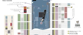
MinimumInterval = ( 1 / ( K * MaximumReasonableFrequency) ) const byte fqPin = 2; // For ATMega32 only 2 or 3. const int K = 1; const unsigned long maxFq = 20000; // rpm (revolutions per minute) const unsigned long minInterval = 1000000UL / ( K * maxFq ); // minimum interval in microseconds volatile unsigned long counter; // Number of samples. volatile unsigned long mks; // Time of the last count. unsigned long oldTime; // Time of the last count in the previous calculation. // Function for handling the interrupt. void ISR() { // Interrupt code here static unsigned long oldTmr; // save the old timer unsigned long tmr=microseconds(); if (tmr - oldTmr > minImterval) { mks=microseconds(); counter++; oldTmr=tmr; } } void setup() { Serial.begin(115200); // Connect the ISR function to interrupt when a signal appears on the fqPin leg. attachInterrupt(digitalPinToInterrupt(fqPin), ISR, RISING); } void loop() { unsigned long rpm; // Receive data. noInterrupts(); unsigned long cnt = counter; counter = 0; unsigned long tmr = mks; interrupts(); // Output the frequency in revolutions per second if (cnt > 0) { rpm = K * 1000000UL / ((tmr - oldTime) / cnt); oldTime = tmr; } else { rpm = 0; } Serial.println(rpm); delay(250); }
Another type of interference is missing samples. Because of the same inertia, your frequency cannot change twice in one millisecond. Obviously, this depends on what you are actually measuring. The frequency of a mosquito's wingbeat can probably drop to zero within a millisecond.
Statistical processing in this case becomes quite complex for a small interrupt handling function, and I am ready to discuss options in the comments.
What types of tachometers are there?
Car inverter 12 220v - how to choose a converter
Mostly there are analog (in the form of a dial with an arrow) and electronic (display) tachometers. More exotic ones - made in the form of a running scale on gas-discharge lamps (often found on American-made cars), as well as mechanical ones - a legacy of the very first cars.
Mechanical
The very first tachometers installed on cars in the early and mid-twentieth century were devices connected directly to the engine crankshaft.
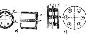
The principle of operation was quite simple: there was a gear on the crankshaft that meshed with a cable drive, which transmitted torque to a coil, which was an electromagnet of the device itself. The more revolutions, the greater the magnetic induction that occurs, the more the needle of the device deviates. Everything is very simple. However, the measurement error was quite high and could reach values of up to 500 rpm.
Analog
Further development led to the emergence of analog tachometers using a similar operating principle. The difference is that instead of being constantly driven by the crankshaft, the frequency of power supplied to the ignition coil is used to read the number of revolutions.
What it looks like in action. To create a spark on the spark plug, a short-term low voltage pulse is applied to the coil that converts low (12V) voltage to high (from 12,000 to 24,000V). The same pulse is supplied simultaneously to the electrical circuit of the analog tachometer and the electromagnet winding. The more pulses are supplied to the winding, the greater the induction force appears, and the greater the angle the arrow deflects.
It should be noted that the error of analog tachometers can range from 100 to 500 rpm.
Digital
Since digital electronic tachometers are increasingly replacing their analog counterparts, not to mention mechanical ones, we will dwell on them in more detail.
The basic principle of operation of a digital tachometer is to measure and count the number of pulses arriving at the primary winding of the ignition coil, or measure the time interval corresponding to these intervals and convert the received information into digital values displayed on the display.
Video - digital tachometer with many settings and Shift Light:
In addition to the fact that a digital tachometer operates on all of the above values, to improve measurement accuracy, the device also processes values coming from the idle speed sensor and, sometimes, the crankshaft sensor. The 1xbet working website has a fairly wide line: there are about 35 different sports. The painting is also impressive, and, of course, the largest number of events is associated with football. However, for other directions there is plenty to choose from. You should also pay attention to eSports events, since this area is only gaining popularity: there are more and more games, as well as events related to them. Placing bets with 1xbet is not only fun and comfortable, but also as profitable as possible. All data is summed up, and the resulting average value is practically a true indicator.
Since approximately half of the total number of cars (especially compact or small cars) are not equipped with a standard tachometer, electronics manufacturers offer installation kits for self-installation of an electronic tachometer.
A simple set represents, in fact, the display itself, often liquid crystal with a built-in board for processing incoming information and a set of wires for connecting to the standard terminals of the coil (the first cylinder with a distributed ignition system), as well as power.
More complex ones may contain additional idle speed sensors, as well as an external optocoupler. However, such kits are installed for a specific purpose - to gain complete control over engine speed. A simple kit is sufficient for everyday use.
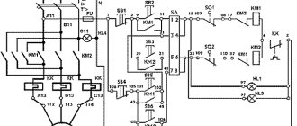
For clarity, below is a typical wiring diagram for an electronic tachometer that receives information only from the ignition coil.
As described above, the tachometer receives the signal from contact K of the ignition coil, which receives low voltage pulses, power is supplied from terminal B of the ignition coil (constant +12V when the ignition is turned on), minus is the vehicle’s weight.
Another version of the tachometer connection diagram - using information from the controller (the “brains”) of the car is shown below.
In this case, to display the number of engine revolutions, information received from the crankshaft position sensor and processed by the controller is used.
Blank for code
Since we are dealing with such delicate quantities as time and space, it is better to immediately master interruptions.
const byte fqPin = 2; // For ATMega32 only 2 or 3. volatile unsigned long counter = 0; // Function for handling the interrupt. void ISR() { // Interrupt code here counter++; // For example } void setup() { Serial.begin(115200); // Connect the ISR function to interrupt when a signal appears on the fqPin leg. attachInterrupt(digitalPinToInterrupt(fqPin), ISR, RISING); } void loop() { // Copy the data. noInterrupts(); unsigned long cnt = counter; interrupts(); // Here we do something with the received data. // ... Serial.println(cnt); delay(1000); }
Pay attention to the volatile modifier for the counter variable. All variables that will be changed in the interrupt handler (ISR) must be volatile. This word tells the compiler that the variable may change unexpectedly and access to it cannot be optimized.
The ISR() function is called every time a 1 appears on the fqPin leg. We do not call this function; the controller itself does this. He does this even when the main program is in a stupor at the delay() function. Consider that ISR() serves an event that is beyond your control and given to you from above like setup() and loop(). The controller interrupts the execution of your program, executes ISR() and returns back to the same point where it interrupted.
Please note that in the loop() function we disable any interruptions at all in order to read the counter variable and save it to the temporary cnt variable. Then, of course, we turn it on again. So we can lose one call, of course, but on the other hand, the unsigned long variable has 32 bits, and the ATMega32 processor is 8-bit, it is unlikely that it will copy the data in one clock cycle, but during the copying process an interruption may occur and some of the data will change . For the same reason, we copy the value of counter locally since the value of this variable when used in different places of the program can be different, again due to its change in the interrupt.
The body of the ISR() function should be as short as possible; more precisely, the function itself should execute as quickly as possible. This is important because it interrupts the execution of your code, which may be susceptible to unexpected delays. Some libraries disable interrupts for latency-sensitive operations, such as driving a WS2812 LED strip.
We count revolutions per unit of time.
The first thing that comes to mind is to take a time interval and count the number of measurements.
Frequency = (Counter / Time) / K const byte fqPin = 2; // For ATMega32 only 2 or 3. const unsigned long interval = 1000000UL; // Counting interval in microseconds const int K = 1; unsigned long oldMks = 0; // previous point in time volatile unsigned long counter = 0; // Function for handling the interrupt. void ISR() { // Interrupt code here counter++; // For example } void setup() { Serial.begin(115200); // Connect the ISR function to interrupt when a signal appears on the fqPin leg. attachInterrupt(digitalPinToInterrupt(fqPin), ISR, RISING); } void loop() { // calculate the current moment in time unsigned long mks=microseconds(); // Receive data. noInterrupts(); unsigned long cnt = counter; counter = 0; // Immediately reset the counter interrupts(); // Print the frequency in revolutions per second Serial.println( 1000000f * (float)cnt / (float)(mks-oldMks) / (float)K ); // 1000000 microseconds in a second // then follow the formula above. // mks-oldMks is better than interval because this is the real time from the last // counter poll, and interval is the estimated time. // We convert all integer variables into real ones oldMks=mks; // Save calculation time. // We sleep while the counts are accumulating until the next calculation delayMicroseconds(interval); }
Like many simple solutions, this one has unobvious disadvantages. To improve measurement accuracy, you need a fairly large time interval. The principle is the same as Quantization Noise. When the wheel rotation time is comparable to the counting time, significant changes in the rotation speed will not be noticed. The readings of such a frequency meter will differ up to two times for each reading.
To increase accuracy at low speed, the K number can be increased, as is done, say, in automotive technology for the ABS sensor. You can increase the counting time. By doing both, we come to the second problem - counter overflow. Yes, overflow is easily cured by increasing the number of bits, but the arithmetic of the Arduino processor cannot count 64-bit numbers as quickly as we would like and as it does with 16-bit ones.
Increasing the calculation time is also not very good because we need to know the frequency right now, when we press the gas, and not in a couple of seconds. And in a couple of seconds we will rather get some kind of average value. During this time, you can do vrumm-vrumm several times.
There is another method. It is devoid of the above-described disadvantages, but, as usual, it has its own.
We count the interval between samples
Frequency = 1 / (Interval * K)
We can time one sample and the other and calculate the difference. The reciprocal of the calculated interval is the frequency. Cool! But there are downsides.
const byte fqPin = 2; // For ATMega32 only 2 or 3. const int K = 1; volatile unsigned long interval; // Function for handling the interrupt. void ISR() { // Interrupt code here static unsigned long oldTime; // Save the previous value. unsigned long Time=microseconds(); interval=Time-OldTime(); oldTime=Time; } void setup() { Serial.begin(115200); // Connect the ISR function to interrupt when a signal appears on the fqPin leg. attachInterrupt(digitalPinToInterrupt(fqPin), ISR, RISING); } void loop() { // Receive data. noInterrupts(); unsigned long cnt = interval; interrupts(); // Output the frequency in revolutions per second Serial.println( 1000000f / ( (float)K * (float)(cnt) ); // 1000000 microseconds per second // further according to the formula above. // All integer variables are converted to real / / We sleep so as not to flood the screen with a stream of data // A quarter of a second is a good time. delay(250); }
What should we do if our wheel is barely spinning and the measured interval exceeds reasonable limits? Above, I suggested that frequencies below a reasonable minimum be considered zero.
A certain disadvantage of the method can be considered quantization noise at high frequencies, when the integer interval is reduced to several binary digits.
I would also like some statistics of calculations to improve the readings, but we take only the last value.
By trial and error, I selected the interval for displaying data on the display at 250ms as optimal. If more often, then the numbers are blurred; if less often, the slowness infuriates.
Combined method
You can try to combine the advantages of both methods.
Frequency = Counter / Measurement Interval / K
That is, we measure the time not just between readings, but the time between data checks and divide by the number of readings during this time. The result is an average interval between samples, the reciprocal of which is the frequency. Let's let the compiler optimize the calculations.
const byte fqPin = 2; // For ATMega32 only 2 or 3. const int K = 1; volatile unsigned long counter; // Number of samples. volatile unsigned long mks; // Time of the last count. unsigned long oldTime; // Time of the last count in the previous calculation. // Function for handling the interrupt. void ISR() { // Interrupt code here mks=microseconds(); // The moment of the last count counter++; // Number of samples } void setup() { Serial.begin(115200); // Connect the ISR function to interrupt when a signal appears on the fqPin leg. attachInterrupt(digitalPinToInterrupt(fqPin), ISR, RISING); } void loop() { unsigned long rpm; // Receive data. noInterrupts(); unsigned long cnt = counter; counter = 0; unsigned long tmr = mks; interrupts(); // Output the frequency in revolutions per second if (cnt > 0) { rpm = 1000000UL / ((tmr - oldTime) / cnt) / K; oldTime = tmr; } else { rpm = 0; } Serial.println(rpm); delay(250); }
Please note that the interval does not count the polling time, as in the first example, but the time from the last count to the previous last count in the last poll. This significantly improves the accuracy of the calculation.
Thus, we can obtain completely reliable data at both low and high frequencies.
If you use cooperative multitasking, you can do the counting, say, every 100ms, and the display every 250ms. A very short polling interval will reduce sensitivity to low frequencies.
As they say in the advertisement, “but that’s not all.”
Operating principle and types
The tachometer receives the signal from the pulse crankshaft speed sensor and converts them into the corresponding numerical value. When using various methods of calculating the control value (direct, reverse, mixed), the reading error reaches 100–500 rpm.
If we touch on the basic diagram of the devices, then in addition to the mechanical tachometer, which can already be considered a rarity, since it is found only on vintage cars, there are two more types of such devices:
- digital;
- analog.
You can also classify devices depending on the installation method:
- standard ones - as a rule, they are installed on the conveyor in a specially designated place on the dashboard of the car;
- remote – mounted outside the dashboard in addition to existing control devices, very often used on sports cars.
Digital tachometer
It is an electronic indicator (screen, display) showing the number of engine revolutions at a given time. It is believed that this representation is most convenient when working with electronic control units or when tuning (tuning) the motor. The device also includes a processor, an analogue to digital signal converter, an idle air valve sensor and another converter that is needed to transform electrical signals into light signals (optocoupler).
Analog tachometer
The appearance of such a device has already been described above. Visually, it is similar to most control and measuring instruments: there is a dial along which an arrow moves, indicating the number of revolutions. The value of the engine crankshaft rotation speed corresponds to the angle of rotation of the arrow relative to the zero value. One of the main elements of such a system is a magnetic coil that accumulates the energy necessary to turn the arrow. The electrical signal from the sensors is supplied through microcircuits to a coil that activates an arrow, which, by its deviation, indicates the value of the control parameter. Sometimes a combined design is used, when in addition to an analog device, a digital one is also installed. However, it is believed that with constant use, the signal from an analog tachometer is perceived by the human brain better than from a digital one.
Features of measuring movement speed and rotation speed.
When measuring the rotation speed of a gasoline engine, it is necessary to take into account the value of K, which is not at all obvious. For example, you wrap a wire around a spark plug cable and expect there to be one spark per turn. It's not like that at all. Firstly, in a 4-stroke engine the flash occurs once per two revolutions, in a 2-stroke engine once per revolution of the crankshaft. Secondly, to simplify the ignition system, the switch supplies a spark to the cylinders that are not currently working, such as at the exhaust. To obtain the correct K, you need to read the documentation for the engine or look at the readings of the reference tachometer.
When measuring driving speed, the display refresh rate doesn't really matter, especially if you're drawing numbers rather than moving the needle. Even updating information once a second will not cause rejection. With engine speed, the opposite is true; the indicator should respond much faster to changes in speed.
Information output
A typical grievance of a novice developer of automobile and motorcycle electronics, “the arrows are twitching, the numbers are unreadable,” can be cured in a simple way - you have to deceive the client. Do you think a car tachometer always shows you the truth? Of course not! Although you like this deception and want your device to fool your head in the same way.
Arrows
If you turn on the ignition on a new fashionable car or motorcycle, the instrument needles will make a beautiful rise to the maximum and slowly fall to zero. Here! This is what we need to do. It is necessary that when the maximum value is shown, the arrow does not instantly rush towards it and does not fall to zero like a scam stock.
So, we need to take into account the maximum speed of the needle for increasing and the maximum speed for decreasing readings. It’s a good idea to make these speeds nonlinear, so that the needle first moves faster and then approaches the set value a little more slowly.
Here is an example with non-linear reading output:
dispRPM(unsigned int rpm) { static unsigned int lastRpm; if (rpm > lastRpm) { // Increases unsigned int disp = rpm — (lastRpm-rpm)/5; // quickly up outputRPM(disp); // Rotate the arrow lastRpm=disp; } else { // Decreases unsigned int disp = rpm — (lastRpm-rpm)/2; // slowly down outputRPM(disp); // Rotate the arrow lastRpm=disp; } }
You can play with the odds. The same principle is used when displaying the volume of a signal, for example, in any analog indicator: arrows, stripes, brightness, color, size, etc. The example given is the simplest, but not the most beautiful. Suggest your options in the comments.
Numbers
With numbers, everything is much more complicated. Rapid changes in readings lead to several orders of magnitude merging into a cloudy spot. For speed, as I wrote above, you can set the interval once per second and the eye will have time to read three digits.
In motorcycles, it’s not for nothing that they make analogue speed indicators; exact numbers are not needed, what is important is the relative proximity to the speed of maximum torque, to the maximum in general and idle.
I suggest changing the frequency of displaying information depending on the degree of change in the value. If the speed changes, say, by 5% from the last count, and not display, you can blunt it and show it once every 300-500ms. If it is 20%, then show it once every 100ms.
You can roughen the scale and show only two significant figures
Taking into account motorcycle topics, you can quite accurately show the idle speed as described just above and coarse the output at speeds from two idle. At high rpm, it is more important for riders to make blinkers like "downshift", "upshift" and "you'll burn the engine". That is, keep the engine near the maximum torque and do not let it spin above the maximum permitted speed. Blinkers are wonderfully made using SmartDelay when you can inherit your own from this class with a given controller leg and blinking frequency, there are methods for overriding and they are called once at a given time.
Ideas for displaying numbers are also welcome in the comments.
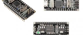
Tachometer with LCD display on microcontroller
There are two options - buy ready-made, or make it yourself. The second way will be within your power if you understand microcontroller technology and know how to program it. In other cases, it is better to purchase a finished product. Again, it should be noted that the VAZ 2101 wiring diagram will be slightly supplemented. First, you need to connect the tachometer to the positive terminal of the ignition switch. VAZ 2107 Replacing the heater radiator! In this video I will show you how to change the heater radiator on a VAZ 2107 car. Secondly, you will need to ensure that the pulses are read. This can be done in two ways:
- Take the signal from the ignition coil.
- Install the proximity sensor on the crankshaft.
The second solution will be more difficult, since you will have to upgrade the crankshaft pulley - you need to make a protrusion on it that will act on the contactless sensor. But taking the signal from the low-voltage output of the coil is a simpler solution.
Circuit diagram of a simple microcontroller tachometer
But you need to remember that during one revolution of the crankshaft exactly two flashes occur in the cylinders. Consequently, two signals will appear on the low-voltage terminal per revolution. This will need to be taken into account when making a tachometer for a VAZ 2101 with your own hands. VAZ 2105, VAZ 2106, VAZ and toe on the VAZ 2101 it is vertical as shown in. How to connect a 220 volt electric motor. In particular, at the stage of programming the microcontroller, this is necessarily taken into account in the algorithm. Which controller to choose is up to you. AtMega128, which has become a classic, will also do an excellent job. You can find a great variety of designs on it.
To control the actuator (in our case, an LCD display), it is advisable to use an amplifier - a Darlington assembly. How to connect the State on-board computer to a VAZ 2110. This is a small microcircuit that allows you to amplify the signal to the required value. Its price is insignificant, at least 10 rubles per piece, so there will be no problems with the purchase. With its help, the tachometer on the VAZ 2101 will be able to work as stably as possible, and there will be no chance that the output ports will be damaged. Be sure to connect the voltage divider to the input port. It will reduce the voltage coming from the ignition coil.
The module is powered from the ignition switch. How to replace the clutch cable on a VAZ 2109? The error when using microcontrollers can be either 3 revolutions per minute or 50. Therefore, study the datasheets and reviews of people who have used the devices for their designs. The photo shows an example of a circuit that can be used for a VAZ tachometer 2101
. It works stably, all that remains is to program it and install it in the dashboard of the penny. Due to its small dimensions, this will be much easier to do than in the case of installing a six indicator.
Video on installing a tachometer in a VAZ 2101:
How to connect a car tachometer with your own hands
The main function of the tachometer in a car is to determine the correct gear, which has a positive effect on the life of the engine. Most cars have an analog tachometer built into them during assembly.
The driver looks at the arrow approaching the red line and knows when to shift into a higher gear.
Not all cars have the type of device that satisfies the owner, so you just need to figure out what they have and how to connect the tachometer.
Did you know? The term “tachometer” comes from the Greek τάχος - speed and μέτρον - measure.
Types of tachometers
There are two types of tachometers: digital and analog.
The first looks like a small screen on which the driver can see all the data he needs while driving.
The second one is simpler and looks like a board with arrows and values.
Remote
A remote tachometer is installed on the front panel of the car. For greater ease of placement, this device has a leg for mounting on the panel.
In addition, their stylish appearance gives the car elegance.
Staff
The standard tachometer is built into the dashboard of the car. This device is more convenient, since it is easier for the driver to perceive the movement of one arrow, rather than several indicators while driving. A standard tachometer is more often used in cars, and manufacturers of electronic devices produce kits for self-equipping cars.
Important! Measuring instruments are produced according to the car brand. Indications from a non-native mechanism will be incorrect
How to connect a tachometer through the computer If your car does not have a carburetor engine, and the injector, the tachometer is not connected to the ignition. In this case, you need to connect the engine control unit to the controller.
The connection diagram for the tachometer is simple: take the ground to the body (ground), connect the plus from the device to the ignition positive. The tachometer has two inputs: the first goes to the control unit, the second to the crankshaft position sensor.
The device connected to the computer will read pulses directly from the control unit controller.
Connection diagram for a tachometer on a gasoline engine
Secure the mechanism in its place (the location is determined by the type of device). Connect the black wire to the ground (body) of the car. Connect the red wire to the ignition switch terminal, which supplies 12 W during operation of the ignition system.
The third wire can be any color. Since the ignition system is contact and non-contact, we will consider where to connect the tachometer in both. With a contact system, the device is connected to the distributor breaker. In the second system - to the voltage switch.
If the car has a display backlight, the tachometer is connected to the terminal provided for this in the ignition switch.
How to connect a tachometer to a diesel engine
Since the process is labor-intensive, it must be carried out in an inspection pit. The first point of work is to dismantle the protective casing of the generator, try to avoid getting dirt. The second step is connecting the tachometer to the diesel generator. To do this, find the terminal marked “W” on the generator body and connect the device output to it.
Attention! It is imperative to close the contact coming from the oil pump. If this is not done, the tachometer may “lie”
It happens that the terminal indicated above cannot be found. In this case, disassemble the generator. Connect one of the wires connecting the winding and the rectifier to the tachometer cable. Insulate the wires and reassemble the generator in reverse order.
How to check the tachometer for functionality
We figured out how to connect a tachometer to a diesel and carburetor engine. Now let's look at the reasons for device breakdowns.
You notice problems in the operation of the measuring device, for example, an arrow jumping in different directions. There may be several reasons for the breakdown. If the engine runs for a long time, vibration will occur, which may damage the display.
The next reason may be oxidation of the contact group of the electrical wiring, damage to its insulation or disconnection from the tips. These are all visible causes that need to be eliminated immediately. If the sensor itself is broken, it needs replacement.
Interesting! The tachometer was designed by the American Curtis Widder in 1903.
Digital index
It's no secret that even expensive cars still use an analog tachometer, which is considered the most comfortable for the eye and the most common for quick reading.
How is this convenient? Firstly, this way you can catch a more suitable moment to change gears. Secondly, such a device is often used by fuel system tuners to achieve optimal engine operating conditions and mixture quality.
Obviously, such technology is more complex, and therefore its use on modern automotive technology is still very limited. The electronic device is based on a liquid crystal display, which is either included in the main analog tachometer or has its own place on the dashboard.
In addition to the display, there is a so-called analog-to-digital converter, which converts pulses from a magnetic coil into a digital signal in binary format. Typically this signal is sent to a digital processor. Its task is to analyze the received data and send it to the display in a form that will be understandable to the end user, the driver. Communication between the devices is carried out by an optocoupler, whose task is to diagnose the idle air valve to compare the received data with the reference data and adjust the output values.