#37. Connecting a 4x4 Arduino matrix keyboard
Today in the lesson we will look at the principle of operation of a 4x4 matrix keyboard . Let's connect a 4x4 keyboard to the Arduino and write a sketch to get values when pressing the buttons .
Technical parameters of the matrix keyboard for Arduino.
Updated: October 19, 2022 Read more...
#36. GSM module SIM800L. AT commands and sending SMS
Today in the lesson we will look at the GSM GPRS SIM800L V2.0 MicroSIM module with antenna . Let's see what its advantages and disadvantages are. Let's figure out how to control this module using AT commands and send a CMC message .
GSM GPRS module has minimal functionality - data exchange with the GSM module via UART. The board has a slot for installing an external SIM card. SIM800L V2.0 GSM/GPRS is a quad-band GSM/GPRS module compatible with Arduino. The module is used to implement GSM and GPRS functions. The advantage of this module is the ability to directly connect it to an Arduino or other microcontroller with a 5V supply voltage.
Updated: September 15, 2022 Read more...
Microcontrollers of the MegaAVR family
| Type | Eg. power supply, V | Tact. Frequency, MHz | I/O | Flash | EEPROM | SRAM | Interfaces | ADC | Timers | ISP | Frame |
| ATmega406 | 4.0 — 25 | 1 | 18 | 40K | 512 | 2K | JTAG TWI | 10x12bit 1x18bit | 1x8bit 1x16bit | I Power-save Power-down Power-off | LQFP48 |
| ATmega48 | 1.8-5.5 | 20 | 23 | 4K | 256 | 512 | UART SPI I2C | 6x10bit 2x8bit | 2x8bit 1x16bit | S | DIP28 TQFP32 MLF32 |
| ATmega48 Avtomotove | 2.7-5.5 | 16 | 23 | 4K | 256 | 512 | UART SPI I2C | 6x10bit 2x8bit | 2x8bit 1x16bit | S | TQFP32 MLF32 |
| ATmega88 | 1.8-5.5 | 20 | 23 | 8K | 512 | 1k | UART SPI I2C | 6x10bit 2x8bit | 2x8bit 1x16bit | S | DIP28 TQFP32 MLF32 |
| ATmega88 Avtomotove | 2.7-5.5 | 20 | 23 | 8K | 512 | 1k | UART SPI I2C | 6x10bit 2x8bit | 2x8bit 1x16bit | S | TQFP32 MLF32 |
| ATmega168 | 1.8-5.5 | 20 | 23 | 16K | 512 | 1k | UART SPI I2C | 6x10bit 2x8bit | 2x8bit 1x16bit | S | DIP28 TQFP32 MLF32 |
| ATmega168 Avtomotove | 2.7-5.5 | 20 | 23 | 16K | 512 | 1k | UART SPI I2C | 6x10bit 2x8bit | 2x8bit 1x16bit | S | TQFP32 MLF32 |
| ATmega8 | 2.7-5.5 | 16 | 23 | 8K | 512 | 1k | UART SPI | 8x10bit | 2x8bit 1x16bit | S | DIP28 TQFP32 MLF32 |
| ATmega16 | 2.7-5.5 | 16 | 32 | 16K | 512 | 1k | UART SPI | 8x10bit | 2x8bit 1x16bit | S | DIP40 TQFP44 MLF44 |
| ATmega32 | 2.7-5.5 | 16 | 32 | 32K | 1K | 2K | UART SPI | 8x10bit | 2x8bit 1x16bit | S | DIP40 TQFP44 MLF44 |
| ATmega64 | 2.7-5.5 | 16 | 53 | 64K | 2K | 4K | 2xUART SPI | 8x10bit | 2x8bit 2x16bit | S | TQFP64 MLF64 |
| ATmega640 | 1,8…5,5 4,5…5,5 | 8 16 | 86 | 64K | 4K | 8K | 4xUART JTAG SPI | 16x10bit | 2x8bit 4x16bit | I | TQFP100 |
| ATmega128 | 2.7-5.5 | 16 | 53 | 128K | 4K | 4K | 2xUART SPI | 8x10bit | 2x8bit 2x16bit | S | TQFP64 MLF64 |
| ATmega1280 | 1,8…5,5 4,5…5,5 | 8 16 | 86 | 128K | 4K | 8K | 4xUART JTAG SPI | 16x10bit | 2x8bit 4x16bit | I | TQFP100 |
| ATmega1281 | 1,8…5,5 4,5…5,5 | 8 16 | 54 | 128K | 4K | 8K | 2xUART JTAG SPI | 8x10bit | 2x8bit 4x16bit | I | TQFP64 |
| AT90CAN32 | 2.7-5.5 | 16 | 53 | 32K | 1K | 2048 | UART JTAG CAN USART | 8x10bit | 2x8bit 2x16bit | S | MLF 64 LQFP 64 |
| AT90CAN64 | 2.7-5.5 | 16 | 53 | 64K | 2K | 4K | UART JTAG CAN USART | 8x10bit | 2x8bit 2x16bit | S | MLF 64 LQFP 64 |
| AT90CAN128 | 2.7-5.5 | 16 | 53 | 128K | 4K | 4K | 2xUART SPI CAN | 8x10bit | 2x8bit 2x16bit | S | TQFP64 MLF64 |
| AT90CAN128 Automotive | 2.7-5.5 | 16 | 53 | 128K | 4K | 4096 | 2xUART SPI CAN | 8x10bit | 2x8bit 2x16bit | S | MLF64 LQFP64 |
| ATmega103 | 4.0-5.5 | 6 | 48 | 128K | 4K | 4K | UART SPI | 8x10bit | 2x8bit 2x16bit | I | TQFP64 |
| ATmega161 | 2.7-5.5 | 8 | 35 | 16K | 512 | 1K | 2xUART SPI | — | 2x8bit 1x16bit | S | DIP40 TQFP44 |
| ATmega162 | 1.8-5.5 | 16 | 35 | 16K | 512 | 1K | 2xUART SPI | — | 2x8bit 1x16bit | S | DIP40 TQFP44 MLF44 |
| ATmega163L | 2.7-5.5 | 8 | 32 | 16K | 512 | 1K | UART SPI | 8x10bit | 2x8bit 1x16bit | S | DIP40 TQFP44 MLF44 |
| ATmega164P/V | 1.8-5.5 | 16 | 32 | 16K | 512K | 1024 | 2xUART SPI+USART TWI | 8x10bit | 2x8bit 1x16bit | S | MLF44 PDIP40 TQFP44 |
| ATmega165 | 1.8-5.5 2.7-5.5 | 8 16 | 53 | 16K | 512 | 1K | UART SPI JTAG PWM | 8x10bit | 2x8bit 1x16bit | S | TQFP64 MLF64 |
| ATmega165P | 1.8-5.5 | 16 | 54 | 16K | 0.5 | 1024 | UART SPI+USI 4PWM | 8x10bit | 2x8bit 1x16bit | S | MLF64 TQFP64 |
| ATmega169 | 1.8-3.6 | 4 | 53 4×25 LCD | 16K | 512 | 1K | UART SPI | 8x10bit | 2x8bit 1x16bit | S | TQFP64 |
| ATmega169P | 1.8-5.5 | 16 | 54 | 16K | 0.5 | 1024 | UART SPI+USI 4PWM | 8x10bit | 2x8bit 1x16bit | S | MLF64 TQFP64 |
| ATmega8515 | 2.7-5.5 | 16 | 35 | 8K | 512 | 512 | UART SPI | — | 2x8bit 1x16bit | S | PDIP40 PLCC44 TQFP,MLF |
| ATmega8535 | 2.7-5.5 | 16 | 32 | 8K | 512 | 512 | UART SPI | 8x10bit | 2x8bit 1x16bit | S | PDIP40 PLCC44 TQFP MLF |
| ATmega2560 | 1,8…5,5 4,5…5,5 | 8 16 | 86 | 256K | 4K | 8K | 2xUART JTAG SPI | 16x10bit | 2x8bit 4x16bit | I | TQFP100 |
| ATmega2561 | 1,8…5,5 4,5…5,5 | 8 16 | 54 | 256K | 4K | 8K | 2xUART JTAG SPI | 8x10bit | 2x8bit 4x16bit | I | TQFP64 |
| ATmega324P/V | 1.8-5.5 | 20 | 32 | 32K | 1K | 2048 | 2xUART SPI+USART TWI | 8x10bit | 2x8bit 1x16bit | S | MLF44 PDIP40 TQFP44 |
| ATmega325 | 1.8-5.5 | 16 | 53 | 32K | 1K | 2K | UART SPI | 8x10bit | 2x8bit 1x16bit | S | TQFP MLF |
| ATmega3250 | 1.8-5.5 | 16 | 68 | 32K | 1K | 2K | UART SPI | 8x10bit | 2x8bit 1x16bit | S | TQFP MLF |
| ATmega325P | 1.8-5.5 | 20 | 54 | 32K | 1K | 2048 | UART SPI | 8x10bit | 2x8bit 1x16bit | S | MLF64 TQFP64 |
| ATmega3250P | 1.8-5.5 | 20 | 54 | 32K | 1K | 2048 | UART SPI | 8x10bit | 2x8bit 1x16bit | S | TQFP100 |
| ATmega329P | 1.8-5.5 | 16 | 54 | 32K | 1K | 2048 | JTAG SPI | 8x10bit | 2x8bit 1x16bit | S | MLF64 TQFP64 |
| ATmega3290P | 1.8-5.5 | 16 | 54 | 32K | 1K | 2048 | JTAG SPI | 8x10bit | 2x8bit 1x16bit | S | TQFP100 |
| ATmega644P/V | 1.8-5.5 | 20 | 32 | 64K | 2K | 4096 | 2xUART SPI+USART TWI | 8x10bit | 2x8bit 1x16bit | S | MLF44 PDIP40 TQFP44 |
| ATmega645 | 1.8-5.5 | 16 | 53 | 64K | 2K | 4K | UART SPI | 8x10bit | 2x8bit 1x16bit | S | TQFP MLF |
| ATmega6450 | 1.8-5.5 | 16 | 68 | 64K | 2K | 4K | UART SPI | 8x10bit | 2x8bit 1x16bit | S | TQFP MLF |
| ATmega644 | 1.8-5.5 2.7-5.5 | 10 20 | 32 | 64K | 2K | 4K | UART SPI TWI PWM JTAG | 8x10bit | 2x8bit 1x16bit | S | PDIP40 TQFP44 MLF44 |
| ATmega329 | 1.8-5.5 | 16 | 53 LCD 4×25 | 32K | 1K | 2K | UART SPI | 8x10bit | 2x8bit 1x16bit | S | TQFP MLF |
| ATmega3290 | 1.8-5.5 | 16 | 68 LCD 4×40 | 32K | 1K | 2K | UART SPI | 8x10bit | 2x8bit 1x16bit | S | TQFP MLF |
| ATmega649 | 1.8-5.5 | 16 | 53 LCD 4×25 | 64K | 2K | 4K | UART SPI | 8x10bit | 2x8bit 1x16bit | S | TQFP MLF |
| ATmega6490 | 1.8-5.5 | 16 | 68 LCD 4×40 | 64K | 2K | 4K | UART SPI | 8x10bit | 2x8bit 1x16bit | S | TQFP MLF |
As can be seen from the table of microcontrollers, there are quite a large number and almost any controller can be “tailored” to the desired task. Let us choose at least one with a detailed description of how to choose and what parameters you generally need to navigate.
- Memory size. Indeed, if we imagine that we need 4 KB of memory and take, for example, ATtiny25, then there simply won’t be enough memory because This MK has only 2 kB of memory. Therefore, it is better to take more. I would choose ATtiny85. There is already 8 KB of memory and, if the functionality is improved, there is some buffer for the program.
- Number of pins. This is probably even more important than point 1. It all depends on the number of I/O ports. Of course, you can connect I2C devices to the pins and poll them directly and output information. But with I2C such MCUs work quite slowly. In our case with the ATtiny85 there are 8 pins (PDIP8 SOIC8 housing, i.e. 8 pins), of which 2 are power supply and we can safely use the remaining 6! During production we need: 1 output for buttons, 1 output for LEDs, 1 output for a relay. 3 more outputs remain free! Those. we have enough memory and conclusions. Especially its size. In the PDIP8 case, several of them will fit on your nail! Price issue. Tinki (ATtiny controllers are what radio amateurs call them) together with a controller for programming via a USB port cost about 80 rubles. Already cheaper. But what's strange. In China, MKs simply cost more than a finished device! Nonsense!
- Supply voltage. Next we will look at working with fuses. So it is these internal switches that indicate how the MK will work. What can this be compared to? For example, you wrote a program on a computer. You turn on the computer and... the computer does not turn on. Why you ask? Well, there can be many reasons: faulty power supply (1 reason), processor (2), memory (3), etc... or maybe the BIOS has simply failed. So it’s the fuses that work like BIOS on a computer - they indicate how the MK core itself will work. You can set the operating frequency of the core, from which generator the MK is synchronized, external or internal, and the limits of the permissible supply voltage at which the MK will operate. The same 85 tinka can be powered with a voltage from 2.7 to 5.5 V. It’s enough just to set the fuses correctly.
In general, we will choose a controller with Flash memory (this is where our program code is written) of at least 8 kB and as cheaply as possible (this is not about minimization, if you need a miniature device, then you should look for a surface-mount microcontroller in TQFP and SO packages). Let's take my favorite MK ATmega8. Its advantages: 8 kB of memory, 28 pins (about 20 of them are ours), there are 512 bytes of non-volatile memory into which we can save and read the necessary data. Price is about 50-60 rubles per piece in China. In total, we have reduced the cost of our project only by MK by at least 2 times. All that remains is to learn how to program the MK.
We will look at 3 programs for programming MK. This will actually be the Arduino IDE shell itself, AVRDUDESHELL and Sinaprog. The simplest is Sinaprog but it needs to prepare a hex file in the Arduino IDE. The most sophisticated one is AVRDUDESHELL. But we will still start with the Arduino IDE since... You can’t go anywhere without it and you just need to know how to use it. Let's start programming.
#35. We display symbols on the LCD 1602 and LCD 2004 display.
, LCD 1602 and LCD 2004 displays are often used. How to connect LCD 1602 to Arduino was discussed in the previous lesson. In addition to text, you often need to display special characters . For example, the designation of temperature is degrees Celsius or percentage of humidity , as well as the direction of advancement or rotation . How to display special characters on the LCD 1602 and LCD 2004 display ? In this lesson, we will look at the output from a set of preset symbols and create our own symbols , which we will also display on the LCD 1602 and LCD 2004 .
Updated: July 8, 2022 Read more...
#34. LCD display LCD 1602 and LCD 2004. Connection to Arduino. Basics.
Character LCD displays LCD 1602 and LCD 2004 are often used in Arduino projects due to their large size and relatively low cost. In addition, these displays are quite easy to work with. Today in the Arduino lesson we will look at the basics of working with LCD 1602 and LCD 2004 LCD displays . Let's connect LCD 1602 to Arduino . And let's look at a couple of examples of sketches that will allow you to display text information on LCD 1602 and 2004.
Description and classification of LCD 1602 and LCD 2004.
Updated: July 8, 2022 Read more...
Getting started with Arduino
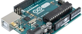
In everyday language, Arduino is an electronic board into which you can plug in many different devices and make them work together using a program written in the Arduino language in a special programming environment.
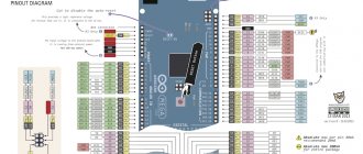
Most often the board looks like this:
The figure shows one of the Arduino boards - Arduino Uno. We will study it in more detail in the following lessons.
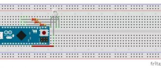
You can plug wires into the board and connect many different elements. Most often, a breadboard for solderless mounting is used for connection. You can add LEDs, sensors, buttons, motors, communication modules, relays and create hundreds of interesting smart device designs. The Arduino board is a smart socket that will turn everything connected on and off depending on how it was programmed.
All work on the project is divided into the following stages:
- We come up with an idea and design it.
- We assemble an electrical circuit. Here we need a breadboard, which simplifies the installation of elements. Of course, you will need skills in working with electronic devices and the ability to use a multimeter.
- We connect the Arduino board to the computer via USB.
- We write a program and write it to the board by literally pressing one button on the screen in a special Arduino programming environment.
- Disconnect from the computer. Now the device will work autonomously - when the power is turned on, it will be controlled by the program that we wrote into it.
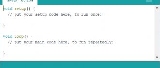
The program and programming environment look like this:
The screen shows a program (in Arduino slang the text of the program is called “sketch”), which will blink with a light connected to input 13 on the Arduino UNO board. As you can see, the program is quite simple and consists of instructions that are understandable for those who know English. The Arduino programming language uses its own dialect of the C++ language, but all C++ features are supported.
There is another option for writing code - a visual editor. There is no need to write anything here - you can simply move the blocks and put together the desired algorithm from them. The program will be loaded into the connected board with one click of the mouse button!
The visual environment is recommended for use by elementary school students; more senior engineers are better off immediately learning the “real” Arduino - it’s quite simple, and besides, knowledge of C++ will not harm anyone.
Overall, everything looks pretty clear, doesn't it? It remains to figure out the details.
#33. Motor shield l293d connection. Example code for Arduino
Robotics is becoming more and more popular every year. And therefore, the amount of electronics with which you can implement a robotic model is quite large. And if you have no experience working with electronics, Motor shield based on the l293d driver is perfect for you. The shield is installed on the Arduino UNO .
The shield contains contacts for connecting DC motors, stepper motors and servos. I have already done a project using this Motor shield. You probably have a question. If the shield is so simple, why do I have few Arduino projects using it? This is due to the difficulty of expanding the functionality of the project when using Motor shield l293d. But first things first.
Updated: June 24, 2022 Read more...
Arduino.ru
The programming language for Arduino devices is based on C/C++. It is easy to learn, and at the moment Arduino is perhaps the most convenient way to program devices on microcontrollers.
Basic and useful knowledge necessary for successful programming for the Arduino platform:
|
|
Arduino Language Reference
The Arduino language can be divided into three sections:
Operators
Control statements
Syntax
Arithmetic operators
Comparison Operators
Logical operators
Unary operators
| DataConstants
Data types
Data type conversion
Variable scope and qualifiers
| FunctionsDigital I/O
Analog I/O
Additional I/O Features
Working with time
Mathematical functions
Trigonometric functions
Random value generators
External interrupts
Data transfer functions
|
Arduino libraries
Servo is a servo drive control library. EEPROM - reading and writing non-volatile memory of the microcontroller. SPI is a library that implements data transfer via the SPI interface. Stepper is a stepper motor control library.