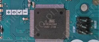
The Arduino Mega 2560 board is based on the ATmega2560 microcontroller. The board has 54 digital I/O pins, 15 of which can be used as PWM outputs, 16 analog inputs, 4 hardware serial UART ports, 16 MHz crystal, USB port, power connector, ISCP (In Circuit Serial Programming) connector , programming in the device using a serial protocol) and a reset button for the microcontroller. In order to start working with this board, you just need to connect it using the USB interface to the computer, or simply supply power from a DC source, which can also be a battery. The Arduino Mega 2560 is compatible with most expansion boards (shields) designed for the Arduino UNO, Duemilanove or Diecimila.
Arduino Mega 2560 replaced the Arduino Mega board.
Mega 2560 differs from all previous boards in that it does not use FTDI USB-to-serial hardware bridges. Instead, it has an ATmega16U2 microcontroller (ATmega8U2 in board versions 1 and 2) programmed to act as a USB-to-serial converter. In the second revision, the Mega2560 has a resistor that pulls the 8U2 HWB line to ground, which makes it easier to switch to DFU mode.
The following changes have been made to the Arduino Mega 2560 in revision 3:
- Pinout 1.0: SDA and SCL pins have been added, located next to the AREF pins, and two other new pins have been placed next to the RESET pin. IOREF allows shields to adapt to the voltage supplied from the board. In the future, shields will be compatible with boards based on AVR microcontrollers, operating at 5 V, and with Arduino Due, operating at 3.3 V.
- The RESET circuit has been strengthened.
- ATmega 8U2 was replaced with 16U2.
Schematic, datasheet, pinout
Download technical manual for microcontrollers ATmega 640/1280/1281/2560/2561:
Datasheet ATmega640/1280/1281/2560/2561 Atmel-2549-8-bit-AVR-Microcontroller-ATmega640-1280-1281-2560-2561_datasheet.pdf
8.4 MiB 2044 Downloads Details
| Category: | Documents |
| Date: | 20.04.2015 |
Download Eagle CAD files for Mega 2560 PCB:
Mega 2560 R3 in Eagle arduino-mega2560_R3-ref-design.zip
156.2 KiB 1322 Downloads Details
| Category: | Documents |
| Date: | 20.04.2015 |
Download the circuit diagram for Arduino Mega 2560:
Mega 2560 R3 circuit diagram arduino-mega2560_R3-sch.pdf
47.1 KiB 2551 Downloads Details
| Category: | Documents |
| Date: | 20.04.2015 |
Pinout diagram of the ATMega2560 microcontroller and their designation on the Arduino board:
Download pin designation as an archived SVG file:
Pinout m/k Mega2560 pin_mapping_mega2560.zip
17.3 KiB 1321 Downloads Details
| Category: | Documents |
| Date: | 20.04.2015 |
Pinout of the Arduino Mega 2560 board (click on the picture to enlarge).
Board based projects
Using the Arduino Mega 2560 made it possible to make a truly large and complex microcontroller system.
For example, there is a very interesting project that has received support in the Russian Federation and is actively developing - this is Arduino Mega Server. The microcontroller is so powerful that it can become an entire server for Internet sites or the cloud.
The only limitation on such a server is the amount of memory, because micro SD memory cards can be used as storage, and Ethernet supports a maximum memory amount of 32 GB.
Arduino Mega Server is a serious project with wide functionality that supports all the technologies a webmaster needs:
- HTML;
- CSS;
- Javascript and others.
On the pages that you create, and their number is limited only by their size and the capacity of your memory card, you can monitor the state of the controller in real time and control its inputs and outputs using buttons on the site’s web interface.
Support for many Javascript libraries will make the interface beautiful and modern.
Using Arduino Mega Server, you can make powerful branched automated control systems with remote control and monitoring of all parameters or home cloud storage.
In the figure below you see a screenshot of the smart home control page from the official website of the project.
Here is a small list of projects implemented with Arduino Mega Server:
- Smart home has already become a classic area of application for Arduino.
- Automated boiler room.
- Greenhouse farming with automatic support of soil humidity and salt composition.
- Weather station.
- And much more.
You receive an operating system for working with Arduino from a computer or smartphone via a web interface.
However, it is worth realizing the capabilities and power of the Arduino Mega 2560 microcontroller, although the board itself is more powerful than its predecessors, but by modern standards it is morally outdated.
These are the same 8 bits and 8 KB of RAM. The speed at which you download data from the server will be small, but it will be enough for web pages.
Characteristics of Arduino Mega 2560
| Microcontroller | ATmega2560 |
| Operating voltage | 5 V |
| Input Voltage (Recommended) | 7-12 V |
| Input voltage (limit) | 6-20 V |
| Digital inputs/outputs | 54 (of which 15 can work as PWM outputs) |
| Analog inputs | 16 |
| Max input/output current | 40 mA |
| Max current for 3.3V output | 50 mA |
| Flash memory | 256 KB of which 8 KB is used by the bootloader |
| RAM (SRAM) | 8 KB |
| Non-volatile memory (EEPROM) | 4 KB |
| Clock frequency | 16 MHz |
Description
Arduino Mega 2560 is an extended version of Arduino Uno, built on the ATmega2560 microcontroller, has more pins - 54 digital inputs/outputs (14 of which can be used as PWM outputs), 16 analog inputs, more hardware serial ports - 4 UART serial ports, 16 MHz crystal oscillator, USB connector, power connector, ICSP connector and reset button.
To work with Mega 2560, you need to connect the platform to your computer via a USB cable or supply power using an AC/DC adapter or battery. The Arduino Mega 2560 is compatible with all expansion boards designed for the Arduino Uno or Duemilanove platforms.
The Arduino Mega 2560 Rev3 is the latest model to replace the previous Arduino Mega 2560 and Mega 1280. The Rev3 version includes an Atmega16U2 chip (in Rev1 and Rev2 Atmega8U2) with USB-to-serial converter firmware, instead of those used in more earlier versions of FTDI chips. The ATmega16u2 microcontroller allows you to use the Arduino Mega2560 controller as a USB HID device. By flashing this microcontroller, the controller can be used as a keyboard, mouse or gaming joystick.
Nutrition
Arduino Mega can be powered from a USB port or an external source. The power source is selected automatically.
External power (not via USB) can be supplied from a power supply or battery. The power supply connects to a 2.1 mm connector on the board, which has a central positive pin. Battery power can be connected to the GND and VIN pins of the POWER connector.
The board can operate from an external voltage source in the range from 6 to 20 volts. If the power supply voltage is less than 7 V, the 5 V pin may have less than 5 V and the board may become unstable. If the external source voltage exceeds 12 V, the voltage regulator may overheat and damage the board. The recommended supply voltage range is 7-12 volts.
Power pins:
- VIN _ Input voltage of the Arduino board when using an external source (if there is no 5 volt voltage from the USB connection or other power source). You can supply power to this pin, or, if power is supplied to the 2.1 mm jack, then you can get the supply input voltage from this pin.
- 5V . The voltage at these pins is regulated by the voltage regulator built into the board. The board can be powered either via the 2.1mm power jack (7-12V), via the USB connection (5V), or via the VIN pin (7-12V) on the board. Supplying power through the 5V or 3.3V pins bypasses the regulator and can damage the board. This is not recommended.
- 3V3 . A voltage of 3.3 volts is generated using a regulator built into the board. The maximum current consumption should not exceed 50 mA.
- GND . Conclusions of the earth.
- IOREF . This pin provides the reference voltage with which the microcontroller operates. To properly configure external boards, you can read the voltage from this pin and select the appropriate power supply or enable voltage converters to operate with 5 V or 3.3 V.
Inputs and outputs
Each of the 54 digital pins on the Arduino Mega can operate in either input or output mode using the pinMode, digitalWrite and digitalRead functions. The outputs operate at 5 V. Each pin can send or receive a maximum of 40 mA and has an internal pull-up resistor of 20-50 kOhm (disabled by default). Plus, some pins have special functions:
- Serial: 0 (RX) and 1 (TX); Serial 1: 19 (RX) and 18 (TX); Serial 2: 17 (RX) and 16 (TX); Serial 3: 15 (RX) and 14 (TX). RX is used to send data over a serial port with TTL logic levels, and TX is used to receive data. Pins 0 and 1 are also connected to the corresponding pins of the ATmega16U2 USB-to-TTL converter chip
- External interrupts: 2 (interrupt 0), 3 (interrupt 1), 18 (interrupt 5), 19 (interrupt 4), 20 (interrupt 3) and 21 (interrupt 2). These pins can be set to low, rising or falling edge, or edge. For more details, see the description of the attachInterrupt function.
- PWM: 2 to 13 and 44 to 46. Provide 8-bit PWM signal output using the analogWrite function.
- SPI: 50 (MISO), 51 (MOSI), 52 (SCK), 53 (SS). These pins support SPI data transfer using the SPI library. SPI pins can also be routed to an ISCP block, which is physically compatible with Uno, Duemilanove and Diecimilia.
- LED: 13. This is a built-in LED on the board, which is connected to pin 13. When the pin is HIGH, the LED turns on; when it is low, the LED turns off.
- TWI (I2C): 20 (SDA) and 21 (SCL). Provides I2C communication using the Wire library. The location of these pins is different on Duemilanove or Diecimila boards.
Mega2560 has 16 analog inputs, each providing 10-bit resolution (1024 different values). By default, the voltage is measured between ground and 5 volts, although it is possible to change the upper range using the AREF pin and the analogReference function. Read more in the article Analog measurements with Arduino.
There are a couple more pins on the board:
- AREF. Reference voltage for analog inputs. Used with analogReference.
- RESET. A low signal at this input resets the microcontroller. Typically, an additional reset button is used on shields that block the reset button on the Arduino board itself.
Briefly about the chip
The ATmega2560 chip is an 8-bit AVR device with 256K ISP Flash memory, the contents of which can be changed by a standard programmer via a serial port or by a program launched by the AVR core code.
The chip is based on the AVR core using RISC architecture.
This allowed the ATmega2560 to achieve 1 million operations per second at a frequency of 1 MHz in one cycle.
Processor pinout diagram
The ATmega2560 chip is manufactured in a plastic QFN/MLF package with 64 pins.
Chip pinout:
| pin | meaning | pin | meaning | pin | meaning | pin | meaning |
| 1 | C0B PG5 | 17 | INT7 PB7 | 33 | PG0 WR | 49 | PA2 AD2 |
| 2 | INT0 PE0 | 18 | SC2 PG3 | 34 | PG1 RD | 50 | PA1 AD1 |
| 3 | INT1 PE1 | 19 | SC1 PG4 | 35 | PC0 A8 | 51 | PA0 AD0 |
| 4 | INT2 PE2 | 20 | RESET | 36 | PC1 A9 | 52 | VCC |
| 5 | INT3 PE3 | 21 | VCC | 37 | PC2 A10 | 53 | GND |
| 6 | INT4 PE4 | 22 | GND | 38 | PC3 A11 | 54 | PF0 ADC7 |
| 7 | INT5 PE5 | 23 | XTAL2 | 39 | PC4 A12 | 55 | PF0 ADC6 |
| 8 | INT6 PE6 | 24 | XTAL1 | 40 | PC5 A13 | 56 | PF0 ADC5 |
| 9 | INT7 PE7 | 25 | SLC PD0 | 41 | PC6 A14 | 57 | PF0 ADC4 |
| 10 | INT0 PB0 | 26 | SDA PD1 | 42 | PC7 A15 | 58 | PF0 ADC3 |
| 11 | INT1 PB1 | 27 | RD1 PD2 | 43 | PG2 ALE | 59 | PF0 ADC2 |
| 12 | INT2 PB2 | 28 | TX1 PD3 | 44 | PA7 AD7 | 60 | PF0 ADC1 |
| 13 | INT3 PB3 | 29 | CP1 PD4 | 45 | PA6 AD6 | 61 | PF0 ADC0 |
| 14 | INT4 PB4 | 30 | CK1 PD5 | 46 | PA5 AD5 | 62 | AREF |
| 15 | INT5 PB5 | 31 | T1 PD6 | 47 | PA4 AD4 | 63 | GND |
| 16 | INT6 PB6 | 32 | T0 PD7 | 48 | PA3 AD3 | 64 | AVCC |
The AREF contact serves to supply a reference voltage relative to which the ADC operates. Its stability determines the accuracy of the readings of all analog signal converters.
Connection
The Arduino Mega 2560 has several different capabilities for communicating with another computer, another Arduino board, or another microcontroller. The ATmega2560 has 4 hardware UART ports for serial communication with TTL levels (5 volts). ATmega16U2 (ATmega 8U2 on revision 1 and 2 boards) redirects one of the channels via USB and provides a virtual COM port for software on the computer (computers running Windows require an .inf file, but computers running Mac OS X and Linux recognize the board as COM port automatically). The Arduino IDE has a port monitor that allows you to send and receive simple text data to the Arduino board. The RX and TX LEDs flash to indicate data is being transferred via the ATmega8U2/ATmega16U2 chip and the USB connection to the computer (but not when data is being transferred via the serial port using pins 0 and 1).
The SoftwareSerial library allows you to work with a serial port connection for any Mega 2560 digital pins.
ATmega2560 also supports I2C and SPI communication. To simplify the use of exchange via the I2C protocol, the Wire library is used, and for communication via SPI, a library with the same name SPI is used.
Microcontroller Capabilities
The use of Arduino Mega 2560 r3 is justified in projects that lack the capabilities of standard Arduino Uno. In 2560, the list of available interfaces has been expanded to the maximum and the number of pins has been increased. Arduino Mega has the most built-in memory among the manufacturer's controllers. Another feature of the board is the use of the ATmega16U2 microcontroller (ATmega8U2 for versions R1 and R2) to convert the USB interface to UART.
Four serial transceivers provide communication between multiple controllers or with a computer.
The 2560 board implements USB board interface overload protection using a resettable fuse. It serves as an additional barrier, despite its own protection in computers. When the load current exceeds 500 mA, the fuse automatically trips. "Arduino Mega Sensor Shield" allows you to connect screens, displays, and various CNC modules to the board. The controller has an SPI interface.
Programming
Arduino Mega can be programmed using the Arduino IDE.
The ATmega2560 microcontroller on the Arduino Mega board comes with a firmware bootloader that allows you to load new code into the microcontroller without using an external hardware programmer. The bootloader uses the original STK500 protocol (C header files).
You can not use a bootloader and program the microcontroller through the pins of the ISCP block using Arduino ISP or similar.
The source code for the ATmega16U2 (or 8U2 in board versions 1 and 2) firmware is available for download in the Arduino repository. ATmega16U2/8U2 boots using the DFU bootloader, which is activated as follows:
- On version 1 boards: close the jumper on the back of the board (next to the map of Italy) and reboot 8U2.
- On version 2 or later boards: There is a resistor that pulls the 8U2/16U2 HWB line to ground, making it easier to enter DFU mode. You can use software from Atmel called Flip (for Windows) or DFU programmer (Mac OS X and Linux). You can also rewrite the firmware with an external programmer using the ISP connector (by rewriting the DFU bootloader). Details here.
Automatic (soft reset)
Instead of physically pressing the reset key before booting, the Arduino Mega 2560 is designed in such a way that it allows a soft reset from the connected computer. One of the lines that controls the data flow of the ATmega8U2, the DTR line, is connected to the reset line of the ATmega2560 through a 100 nF capacitor. Activating this line using a low voltage level allows the chip to be reset. The Arduino software takes advantage of this by allowing you to download code by simply clicking the download button in the Arduino environment. The low level signal is synchronized with the start of code recording, which reduces the bootloader timeout.
This has another application. When the Mega 2560 is connected to a computer running Mac OS X or Linux, a soft reboot (via USB) occurs every time. The bootloader program on the Mega 2560 takes about half a second to complete. During the programming process, the first few bytes of the code are delayed to avoid receiving incorrect data (all except the code of the new program). If you are doing a one-time debugging of a sketch written into the platform, or entering any other data at the first launch, you need to make sure that the program on the computer waits for a second before transferring the data.
On Mega2560 it is possible to disable the automatic reboot line by breaking the corresponding line. To restore the line, it is necessary to reconnect the contact at the break. The line is labeled "RESET-EN". It is also possible to disable automatic reboot by connecting a 110 Ohm 5 V resistor and this line. Details here.
Advantages and disadvantages of ATmega 2560
The advantages of ATmega 2560 include:
- flexibility of control algorithms without changing the hardware of the unit;
- large frequency range of processed signals;
- small size and weight of the block;
- convenience and ease of replacing blocks;
- chip reliability;
- many diagnostic points for analog and digital parts;
- the ability to quickly change work algorithms in emergency situations;
- absence of parameter drift, which is inherent exclusively in analog equipment.
Disadvantages of digital systems based on ATmega 2560:
- the need to use a large number of DACs and ADCs (digital-to-analog and analog-to-digital converters);
- increased system response time due to multiple signal conversion;
- the difficulty of directly transferring analog algorithms to a digital system;
- increasing the time and cost of developing software that implements control algorithms;
- increased requirements for signal conversion time to DAC and ADC;
- increasing complexity of equipment production technology;
- increasing requirements for the capacity and speed of a digital computer;
- the impact of the quality of the developed software on the uninterrupted and error-free operation of the entire control system.
Physical characteristics and compatibility with expansion cards
The length and width of the Mega2560 PCB are 10.2 and 5.3 cm, respectively. The USB connector and power connector exceed these dimensions. Three holes in the board allow it to be mounted on a surface. The distance between digital pins 7 and 8 is 0.4 cm, although between the other pins it is 0.25 cm.
The Arduino Mega2560 is compatible with all expansion boards designed for the Uno, Duemilanove or Diecimila platforms. The layout of pins 0 – 13 (and adjacent AREF and GND), analog inputs 0 – 5, power connector, ICSP block, UART serial port (pins 0 and 1) and external interrupt 0 and 1 (pins 2 and 3) on Mega corresponds to location on the above platforms. SPI communication can be done via the ICSP block on both the Duemilanove/Diecimila and Mega2560 platforms. However, the layout of the I2C communication pins (20 and 21) on the Mega platform does not match the layout of the same pins (analog inputs 4 and 5) on the Duemilanove/Diecimila.
Arduino.ru
General information
Arduino Mega is built on the ATmega2560 microcontroller (technical description).
The board has 54 digital inputs/outputs (14 of which can be used as PWM outputs), 16 analog inputs, 4 UART serial ports, a 16 MHz crystal oscillator, a USB connector, a power connector, an ICSP connector, and a reset button. To operate, you need to connect the platform to your computer via a USB cable or supply power using an AC/DC adapter or battery. The Arduino Mega 2560 is compatible with all expansion boards designed for the Uno or Duemilanove platforms. Scheme and initial data
EAGLE files: arduino-mega2560-reference-design.zip
Schematic diagram: arduino-mega2560-schematic.pdf
Brief characteristics
| Microcontroller | ATmega2560 |
| Operating voltage | 5V |
| Input Voltage (Recommended) | 7-12V |
| Input voltage (limit) | 6-20V |
| Digital Inputs/Outputs | 54 (14 of which can also function as PWM outputs) |
| Analog inputs | 16 |
| DC current via input/output | 40 mA |
| Constant current for 3.3V output | 50 mA |
| Flash memory | 256 KB (of which 8 KB is used for the bootloader) |
| RAM | 8 KB |
| Non-volatile memory | 4 KB |
| Clock frequency | 16 MHz |
Nutrition
Arduino Mega can be powered either via a USB connection or from an external power source. The power source is selected automatically.
External power (not USB) can be supplied via an AC/DC voltage converter (power supply) or a battery. The voltage converter is connected via a 2.1 mm jack with a positive pole on the central pin. The wires from the battery are connected to the Gnd and Vin pins of the power connector (POWER).
The platform can operate with external power from 6V to 20V. When the supply voltage is below 7V, the 5V pin may output less than 5V, and the platform may become unstable. If you use voltage higher than 12V, the voltage regulator may overheat and damage the board. Recommended range is 7V to 12V.
The Mega2560 board, unlike previous versions of boards, does not use an FTDI USB microcontroller. To exchange data via USB, an Atmega8U2 microcontroller is used, programmed as a USB-to-serial converter.
Power pins:
- VIN _ The input is used to supply power from an external source (in the absence of 5V from the USB connector or other regulated power source). The supply voltage is supplied through this pin. If power is supplied to the 2.1mm connector, then this input can be powered.
- 5V . A regulated voltage source used to power the microcontroller and on-board components. Power can be supplied from the VIN pin via a voltage regulator, or from a USB connector or other regulated 5V source.
- 3V3. The 3.3V pin voltage is generated by the FTDI chip on the platform. Maximum current consumption 50 mA.
- GND. Grounding terminals.
Memory
The ATmega2560 microcontroller has: 256 kB of flash memory for storing program code (4 kB is used to store the bootloader), 8 kB of RAM and 4 kB of EEPROM (which is read and written using the EEPROM library).
Inputs and Outputs
Each of the Mega's 54 digital pins can be configured as an input or output using the pinMode(), digitalWrite(), and digitalRead() functions. The pins operate at a voltage of 5 V. Each pin has a load resistor (standard disabled) of 20-50 kOhm and can pass up to 40 mA. Some pins have special functions:
- Serial bus: 0 (RX) and 1 (TX); Serial bus 1: 19 (RX) and 18 (TX); Serial bus 2: 17 (RX) and 16 (TX); Serial bus 3: 15 (RX) and 14 (TX). The pins are used to receive (RX) and transmit (TX) TTL data. Pins 0 and 1 are connected to the corresponding pins of the ATmega8U2 serial bus chip.
- External interrupt: 2 (interrupt 0), 3 (interrupt 1), 18 (interrupt 5), 19 (interrupt 4), 20 (interrupt 3), and 21 (interrupt 2). These pins can be configured to trigger an interrupt either on a low value, a rising or falling edge, or when a value changes. See the attachInterrupt() function for details.
- PWM: 2 to 13 and 44-46. Either pin provides 8-bit PWM using the analogWrite() function.
- SPI: 50 (MISO), 51 (MOSI), 52 (SCK), 53 (SS). These pins enable SPI communication, for example using the SPI library. Also, SPI pins can be output on the ICSP block, which is compatible with the Uno, Duemilanove and Diecimila platforms.
- LED: 13. Built-in LED connected to digital pin 13. If the pin value is high, the LED is lit.
- I2C: 20 (SDA) and 21 (SCL). The pins provide I2C (TWI) communication. To create it, the Wire library is used (information on the Wiring website). The pin layout on the Mega platform does not match that of the Duemilanove or Diecimila.
The Mega2560 platform has 16 analog inputs, each with a resolution of 10 bits (i.e., can take 1024 different values). The standard pins have a measurement range of up to 5 V relative to ground, however it is possible to change the upper limit using the AREF pin and the analogReference() function.
Additional pair of platform pins:
- AREF. Reference voltage for analog inputs. Used with the analogReference() function.
- Reset. A low signal on the pin resets the microcontroller. Typically used to connect a reset button on an expansion board, which blocks access to the button on the Arduino board itself.
Connection
The Arduino Mega2560 platform contains several devices to communicate with a computer, other Arduino devices or microcontrollers. ATmega2560 supports 4 UART serial data ports for TTL. The ATmega8U2 chip installed on the board routes one of the interfaces via USB, providing a virtual COM port to programs on the computer (Windows machines require an .inf file to work correctly with a virtual COM port; systems based on OSX and Linux automatically recognize the COM port). The Arduino development environment's Serial Monitor utility allows you to send and receive text data when connected to the platform. The RX and TX LEDs on the platform will blink when data is being transmitted via the ATmega8U2 chip and USB connection (but not when using serial transmission via pins 0 and 1).
With the SoftwareSerial library it is possible to create serial data transmission through any of the Mega2560 digital pins.
ATmega2560 supports I2C (TWI) and SPI interfaces. Arduino includes a Wire library for easy use of the I2C bus. More information is available on the Wiring website. For SPI communication, the SPI library is used.
Programming
The platform is programmed using the Arduino development environment. Detailed information can be found in the manual and instructions.
The ATmega2560 microcontroller comes with a pre-written bootloader, making it easy to write new programs without the use of external programmers. Communication is carried out using the original STK500 protocol.
It is possible not to use a bootloader and program the microcontroller through the pins of the ICSP block (in-circuit programming). Detailed information can be found in this manual.
The firmware code for the ATmega8U2 controller is available for free download. The ATmega8U2 controller has its own DFU bootloader, which can be activated by closing the jumper on the back of the board (next to the map of Italy) and rebooting the controller. To write new firmware, you can use Atmel's FLIP (on Windows) or DFU programmer (on Mac OS X or Linux). You can also rewrite the firmware with an external programmer using the ISP input.
Automatic (soft) reboot
Mega is designed in such a way that before writing a new code, a reboot is carried out by the program itself, and not by pressing a button on the platform. One of the ATmega8U2 data flow control (DTR) lines is connected to the reset pin of the ATmega2560 microcontroller through a 100 nF capacitor. Activation of this line, i.e. sending a low level signal reboots the microcontroller. The Arduino program, using this function, uploads the code with one click of the Upload button in the programming environment itself. The low level signal on the DTR line is coordinated with the start of code recording, which reduces the bootloader timeout.
The function has another application. The Mega2560 reboots every time it is connected to the Arduino program on a Mac X or Linux computer (via USB). For the next half second after the reboot, the bootloader works. During programming, the first few bytes of the code are delayed to prevent the platform from receiving incorrect data (everything except the code of the new program). If you are doing a one-time debugging of a sketch written into the platform, or entering any other data the first time you run it, you need to make sure that the program on your computer waits for a second before transferring the data.
On Mega2560 it is possible to disable the automatic reboot line by breaking the corresponding line. The chip contacts at both ends of the line can then be connected for recovery purposes. The line is marked "RESET-EN". It is also possible to disable automatic reboot by connecting a 110 Ohm resistor between the 5 V source and this line.
USB connector current protection
The Arduino Mega2560 has a built-in resettable fuse link that protects the computer's USB port from short circuit and overcurrent currents. Although almost all computers have similar protection, this fuse nevertheless provides an additional barrier. The fuse automatically interrupts data exchange when a current of more than 500 mA passes through the USB port.
Physical characteristics and compatibility with expansion cards
The length and width of the Mega2560 PCB are 10.2 and 5.3 cm, respectively. The USB connector and power connector exceed these dimensions. Three holes in the board allow it to be mounted on a surface. The distance between digital pins 7 and 8 is 0.4 cm, although between the other pins it is 0.25 cm.
The Arduino Mega2560 is compatible with all expansion boards designed for the Uno, Duemilanove or Diecimila platforms. The layout of pins 0 – 13 (and adjacent AREF and GND), analog inputs 0 – 5, power connector, ICSP block, UART serial port (pins 0 and 1) and external interrupt 0 and 1 (pins 2 and 3) on Mega corresponds to location on the above platforms. SPI communication can be done via the ICSP block, both on the Duemilanove/Diecimila and Mega2560 platforms. However, the pin layout (20 and 21) of the I2C communication on the Mega platform does not match the pin layout (analog inputs 4 and 5) on the Duemilanove/Diecimila.
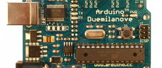
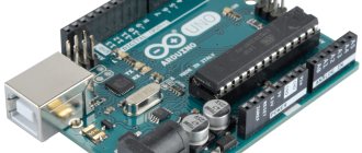
Photo Arduino.cc