Arduino is one of the most popular microcontrollers today. We will not describe all the advantages of this assembly, because if you came here, then obviously for a reason, but apparently you realized that you cannot do without it. We also guess that you are tormented by a completely different question... Is it possible to power Arduino with 12 volts? After all, when we work with a computer from USB, the Arduino is powered by the same computer - 5 volts. Everything is fine here, everything is agreed and there are no problems! But as soon as the Arduino “goes to work”, its power supply via the wire from the computer is interrupted like the umbilical cord of a newborn, and everyone has to feed :) This is where you have to be tricky. So, how can you power the Arduino?
Most boards require power in the range of 4.5 to 9 volts via the external power connector and 4.5-5 volts via USB. However, the instructions say 7-12 volts, that is, we will assume that the optimal option is 9 volts.
In fact, from 9 volts on the board, 5 and 3.3 volts are obtained. For each 5 and 3.3 V power supply circuit, the board has its own voltage regulator. Let's say in the photo this is an lm1117 stabilizer for 5 volts, and then 3.3 volts. We will be interested in the 5-volt stabilizer, since it is on it that the voltage will be suppressed, and therefore the power will be dissipated when an overvoltage is applied. Let's figure out what and how.
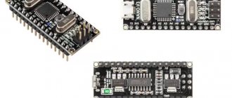
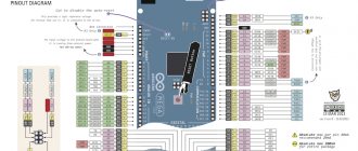
Arduino Nano board pinout
There are pin contacts on both sides of the board, 15 on each side.
Contact assignment:
- 1, 2: work with the UART interface;
- 3, 28: microcontroller reset;
- 4, 29: common wire;
- 5: external interrupt;
- 6: External interrupt/create pulse width modulated signal;
- 7: work with I2C interface / timer-counter 0;
- 8: work with I2C interface / create PWM signal / timer-counter 1;
- 9, 12: creating a PWM signal;
- 10, 11: digital I/O pins, no special functions;
- 13, 14, 15: working with the SPI interface / creating a PWM signal;
- 16: LED connection / work with SPI interface;
- 17: power supply 3.3V;
- 18: reference voltage for ADC;
- 19-26: analog inputs (AP) for ADC;
- 27: 5V power supply;
- 30: VIN 7-12V input signal.
Arduino Nano has 14 digital ports (DP) and 8 AP.
Arduino powered by 12 volts
Here again there are two options for where to get 12 volts, it’s either a power supply or a battery. Yes, yes, Arduino is quite actively used in cars, and there are 12-14 volts - everywhere! It is motorists that we will focus on. So 14 volts, how much should lm1117 be extinguished. It’s easy to calculate 14-5 = 9 volts. We calculate how much needs to be dispersed.
P=U*I=9*0.25= 2.25 W. Here the dissipated power has increased by as much as 2.5 times, everything is generally proportional to the voltage. Here the question is whether lm1117 will hold up or not. If you look at the datasheet, these are babies, then the output current is 0.8 A, but at a voltage of 1.2 V, that is, it produces a power of 1.2 * 0.8 = 0.96 W. Of course, the possible dissipated power and the possible output are still different things, but somehow these values must be compared... In addition, the voltage with which the lm1117 operates is up to 13.8 volts. What can save you is the implemented protection against overheating and short circuit in the microcircuit. At least in the SOT-223 case like ours, you shouldn’t connect the lm1117 to 14 volts. All this is at your own peril and risk, and if you really want to, then with a current of no more than 1-2 LEDs, that is, 70-80 mA.
How can you still connect it to 12 volts, receiving 7-9 volts and powering the Arduino? It is best to use a converter or a voltage stabilizer microcircuit with a more developed housing, say we use the lm7809 or KREN9 microcircuit, which is the same thing. The TO-220 case, and even better, fit it on a 5-10 sq. m radiator. cm made of aluminum. The current in this case is up to 2 A. Such a microcircuit with a radiator should be enough! The following is a connection diagram for 7805, but 7809 is connected one to one!
Of course we install this assembly before the power connector. As a result, the power dissipation per voltage drop of 2.25 W will be dissipated partly on the lm7809 and partly in the Arduino lm1117 itself.
Board specifications
| Nutrition | 5 V |
| Input signal | 7-12 V (DC) |
| Number of DP | 14 (6 for PWM) |
| Number of APs | 8 |
| Maximum current DP | 40 mA |
| Flash format memory | 16 / 32 KB |
| RAM | 1 / 2 KB |
| EEPROM format memory | 512 bytes / 1 KB |
| Microcontroller clock frequency | 16 MHz |
| Dimensions | Width - 19 mm, length - 42 mm |
| Weight | 7 g |
A detailed overview of the board's capabilities is provided in the Datasheet - technical documentation. Detailed characteristics and description of AN are also indicated there.
Characteristics
The board is based on the ATmega 328 processor. In addition to it, the board contains a USB module for communication with a computer and firmware. This module is called "USB-TTL converter". On branded Arduino Uno boards, an additional ATmega16U2 .
| Characteristics | Arduino Uno R3 |
| Microcontroller | ATmega328 |
| Operating voltage | 5V |
| Supply voltage (recommended) | 7-12V |
| Supply voltage (limit) | 6-20V |
| Digital inputs/outputs | 14 (of which 6 can be used as PWM outputs) |
| Analog inputs | 6 |
| Maximum current per pin | 40 mA |
| Maximum pin output current 3.3V | 50 mA |
| Flash memory | 32 KB (ATmega328) of which 0.5 KB is used by the bootloader |
| SRAM | 2 KB (ATmega328) |
| EEPROM | 1 KB (ATmega328) |
| Clock frequency | 16 MHz |
The peculiarity of this chip is its hardware support for USB, which allows communication without additional converters. While ATmega328 does not support such a function, so 16u2 acts as a data converter from USB to serial port for the AVR MK. It contains a program to perform this task.
However, this is not always the case: smaller boards, such as the Arduino Nano, use level converters based on various chips, for example FT232, CP21XX, Ch340g and the like. This solution is cheaper and does not require flashing an additional link controller as described above.
Attention ! Not everything is so simple with DCcduino UNO r3 on ch340g. It uses a cheaper version of the USB-TTL converter than the original.
The board has a 3.3 V output, it is needed to connect peripherals and some sensors, its current capacity is 50 mA.
ATmega328 operates at 16 MHz. It is fixed by a quartz resonator, which you can, if desired, replace, thereby speeding up the operation of the Uno r3.
Important! After replacing the crystal, time-related functions such as Delay will not match the entered values. This is a time delay function, by default its argument is the required delay time in ms. The function is written in the Arduino libraries, taking into account the standard clock frequency of 16 MHz. Therefore, after replacing the quartz, the specified time will not correspond to what was written. To do this, you need to either select experimentally and install dependencies, or edit library files.
Electric scheme
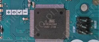
The most important elements of the Arduino Nano board are the programmer (ISCP connector) and the microcontroller (ATmega328P). It is necessary for everyone who is going to work with this board to know their structural, circuit diagrams and the purpose of contacts.
ISCP circuit "Arduino Nano"
ISCP connector (or SPI) is a programmer through which the sketch (code for the board’s microcontroller) is loaded into the ATmega328P. It has 6 contacts. The hole of the first of them is made in the shape of a square for ease of reference.
Connector pinout:
- MISO: Master input, slave output when transmitting data.
- +VCC: supply voltage.
- SCK: serial clock signal.
- MOSI: master output, slave input when transmitting data.
- Reset: reset.
- GND: common wire.
Schematic diagram of the board controller
The board controller is ATmega328P. The core of the chip is the CPU, to which there are 2 buses (data bus and input/output data bus), control elements (for example, the Reset pin, responsible for resetting the microcontroller) and memory.
Types of memory in the controller:
- SRAM;
- Flash;
- EEPROM
The following elements go to the data bus:
- Watchdog timer.
- ADC.
- External interrupt.
- The first and second timer-counters.
- USART and I2C (Atmel calls this interface TWI).
The following are connected to the data input/output bus:
- I/O ports.
- Zero timer-counter.
- SPI interface.
The controller can be implemented in both MLF and PDIP packages. The Arduino Nano has an MLF version of the microcontroller installed.
Power Options for Arduino Nano
Three power options for Arduino Nano
Via USB, the board receives power from the computer when debugging the program or from a Power Bank. USB power is 5 volts (approximately, I found 4.6 - 5.1 V). As far as I understand, these 5 volts immediately “fall through” to the 5V leg. That is, we can assume (although the issue is debatable) that power from USB is not particularly different from supplying voltage from the corresponding wires of the USB cable to the 5V leg.
The Vin leg supplies external power with a voltage higher than 5 volts. The upper value is sometimes indicated as 12 volts, and sometimes 9. The lower value should be more than 5 volts with some margin. The external voltage passes through the “lower”, a microcircuit with a harness that turns the higher voltage into 5 volts. Again, we can assume that these converted five volts end up on the 5V pin. This chip is located on the back of the board.
The 5V leg is the most mysterious, because at first glance it looks like a voltage output (output) from the board for powering external modules, such as digital indicators, sensors, etc. Moreover, when the entire project is powered through Vin, this is the case.
In fact, it is more correct to consider that the 5V pin is the main input for powering the Arduino. That is, when powered from USB, the input voltage is connected to this pin and the Arduino chip and connected external devices are powered from it. When powered through Vin, the same thing happens, but through the built-in step-down switch. And when power comes directly from the 5V leg, everything happens quite naturally. The description of the board in this regard seemed to me to be insufficiently clear, so I will not provide it.