The principle of load control via Arduino
The Arduino board has two types of output ports: digital and analog (PWM controller). A digital port has two possible states: logical zero and logical one. If you connect an LED to it, it will either glow or not.
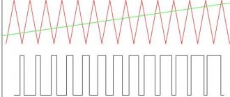
The analog output is a PWM controller, to which a signal with a frequency of about 500 Hz is supplied with an adjustable duty cycle. What a PWM controller is and the principle of its operation can be found on the Internet. Through the analog port it is possible not only to turn the load on and off, but also to change the voltage (current) on it.
Command Syntax
Digital output:
pinMode(12, OUTPUT); — set port 12 to be the data output port; digitalWrite(12, HIGH); — we apply a logical one to discrete output 12, lighting the LED.
Analog output:
analogOutPin = 3; – set port 3 to output an analog value; analogWrite(3, value); – we generate a signal at the output with a voltage from 0 to 5V. The value is the duty cycle of the signal from 0 to 255. At a value of 255, the maximum voltage.
Ways to control LEDs via Arduino
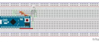
Only a weak LED can be connected directly through the port, and even then it is better through a limiting resistor. Trying to connect a more powerful load will damage it.
For more powerful loads, including LED strips, an electronic switch – a transistor – is used.
Various programs
Libraries with programs for the Arduino board can be downloaded from the official website or found on the Internet on other information resources. If you have the skills, you can even write a sketch program (source code) yourself. To assemble an electrical circuit, no specific knowledge is required.
Application options for a system running Arduino:
- Lighting. The presence of a sensor will allow you to set a program according to which the light in the room either appears immediately or gradually turns on parallel to sunset (with increasing brightness). To enable, you can use Wi-Fi, telephone and integration into the Smart Home system.
- Lighting of the corridor and staircases. Arduino will allow you to organize the lighting of each part (for example, a step) separately. Add a motion sensor to the board so that the addressable LEDs light up sequentially depending on the location where the movement of the object is detected. If there is no movement, the diodes will go out.
- Light music. Use filters and send audio signals to the analog input to create light music (equalizer) at the output.
- Computer modernization. Some sensors will allow you to create a dependence of the color of the LEDs on the temperature of the processor, its load, and the load on the RAM. The DMX 512 protocol is used.
Arduino chips expand the possibilities of using monochrome and multi-channel (RGB) LED strips. In addition to the merging of different colors, the formation of hundreds of thousands of shades, you can create unique effects - fading when the sun sets, periodically turning on/off when motion is detected, and much more.
Types of transistor switches
- Bipolar;
- Field;
- Composite (Darlington assembly).
| Load connection methods | ||
| Via bipolar transistor | Via field effect transistor | Via voltage switch |
When a high logic level (digitalWrite(12, HIGH);) through the output port to the base of the transistor, a reference voltage will flow to the load through the collector-emitter circuit. This way you can turn the LED on and off.
A field-effect transistor works in a similar way, but since instead of a “base” it has a drain, which is controlled not by current, but by voltage, a limiting resistor in this circuit is not necessary.
The bipolar view does not allow you to regulate powerful loads. The current through it is limited to 0.1-0.3A.
Field-effect transistors operate with more powerful loads with currents up to 2A. For an even more powerful load, Mosfet field-effect transistors are used with a current of up to 9A and a voltage of up to 60V.
Instead of field ones, you can use a Darlington assembly of bipolar transistors on ULN2003, ULN2803 microcircuits.
ULN2003 chip and circuit diagram of an electronic voltage switch:
How to save data in Arduino nodemcu internal memory
For this task we will use several commands: EEPROM.read and EEPROM.write. We will save not only the login and password for Wi-Fi, we will save: wifi, user transition settings. To do this, we will write several functions:
- Write to EEPROM memory
- Reading from EEPROM memory
- Clearing EEPROM memory
Separately, I would like to say about cleaning, it is absolutely necessary and will need to be called every time before recording. The recording occurs byte by byte, I will call each byte a cell. We will have our own cleaning, we will not reset the bytes, we will write our own “#” symbol in each cell, this will make it easier for us and it will be more clear. I have defined three memory ranges with which we will work: from cells 20 to 90 we will store data for connecting to wifi, from 90-100 the user transition data and from 100-2000 we will store the user transitions themselves, I think this is enough for us. After that, we write the code for our functions:
//************************************************ *** void ClearEprom(int s1, int s2) { EEPROM.begin(2000); for (int i = s1; i < s2; i++) { EEPROM.write(i, 35); } EEPROM.commit(); EEPROM.end(); } //****************************************************** **** void EEPROM_writeAnything(int ee, String val) { EEPROM.begin(2000); byte *text; int len; len = val.length() + 1; unsigned char* buf = new unsigned char; val.getBytes(buf, len, 0); for (int i = 0; i < len; i++) { int s; s = ee + i; byte sim; sim = byte(buf); EEPROM.write(s, sim); } EEPROM.commit(); EEPROM.end(); } //****************************************************** **** String ReadEprom(int s, int count) { EEPROM.begin(2000); String txt; unsigned int i; for ( i = s; i < (s + count - 1); i++) { if (EEPROM.read(i) == 35) { break; } txt += char(EEPROM.read(i)); } EEPROM.commit(); EEPROM.end(); return txt; }
In the clearing function, we simply write our character with code 35 using the specified range. In the recording function, we take the value of the cell from which we are recording and the value of the row itself. In the reading function, we get the value of the byte from which we are reading and the last possible byte, but we also add an exit condition if we encounter our “zero” byte with code 35 and return a text string
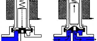
The principle of operation of a transistor for smooth control of an LED strip
A transistor works like a water faucet, only for electrons. The higher the voltage applied to the base of the bipolar transistor or the drain of the field effect transistor, the lower the resistance in the emitter-collector circuit, the higher the current passing through the load.
Having connected the transistor to the Arduino analog port, we assign it a value from 0 to 255, and change the voltage supplied to the collector or drain from 0 to 5V. The collector-emitter circuit will pass from 0 to 100% of the load reference voltage.
To control an Arduino LED strip, you need to select a transistor of suitable power. The operating current for powering the LED meter is 300-500mA; a power bipolar transistor is suitable for these purposes. For longer lengths, a field effect transistor will be required.
Connection diagram for LED strip to Arduino:
Connecting to Arduino
Direct connection of the LED strip to Arduino is only appropriate when using weak LED diodes. For an LED strip, additional electrical elements must be installed between it and the board.
Via relay
Connect the relay to the Arduino board via digital output. The controlled strip can have one of two states - on or off. If you need to organize control of an RGB strip, you will need three relays.
The current controlled by this device is limited by the power of the coil. If the power is too low, the element will not be able to close large contacts. For the highest powers, use relay assemblies.
Using a bipolar transistor
If you need to increase the current or voltage at the output, connect a bipolar transistor. When choosing it, focus on the load current. The control current does not exceed 20 mA, so add a 1 - 10 kOhm resistor to limit the current through resistance.
Note! Ideally, you need to use an NPN type transistor based on a common emitter. If high gain is required, use a transistor assembly.
Using a field effect transistor
Instead of bipolar transistors, use field-effect transistors (abbreviated as MOS) to control LED strips. The difference between them is related to the control principle: bipolar ones change the current, field ones change the gate voltage. Thanks to this, a small gate current drives a large load (tens of amperes).
Be sure to add a current limiting resistor to the circuit. Due to the high sensitivity to noise, a 10 kOhm resistor mass is connected to the controller output.
Using expansion cards
If you don’t want to use relays and transistors, you can buy entire blocks - expansion boards. These include Wi-Fi, Bluetooth, equalizer, driver, etc., which are required to control loads of different powers and voltages. These can be either single-channel elements, which are suitable for monochrome tapes, or multi-channel (for controlling RGB color tapes).
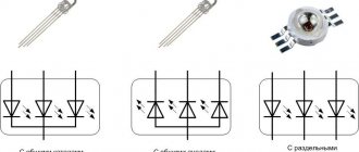
Controlling RGB strip with Andurino
In addition to single-chip LEDs, Arduino can also work with color LEDs. By connecting the pins of each color to the analog outputs of Arduino, you can arbitrarily change the brightness of each crystal, achieving the desired color of glow.
Connection diagram for Arduino RGB LED:
The Arduino RGB strip control is constructed similarly:
It is better to assemble the Arduino RGB controller using field-effect transistors.
For smooth brightness control, you can use two buttons. One will increase the brightness of the glow, the other will decrease it.
Arduino LED strip brightness control sketch
int led = 120; set the brightness to medium level
void setup() { pinMode(4, OUTPUT); set the 4th analog port to pinMode(2, INPUT);
pinMode(4, INPUT); set the 2nd and 4th digital ports to input for polling buttons } void loop(){
button1 = digitalRead(2);
button2 = digitalRead(4); if (button1 == HIGH) pressing the first button will increase the brightness { led = led + 5;
analogWrite(4, led); } if (button2 == HIGH) pressing the second button will decrease the brightness { led = led - 5;
analogWrite(4, led); }
When you hold down the first or second button, the voltage supplied to the control contact of the electronic key smoothly changes. Then there will be a smooth change in brightness.
Arduino RGB backlight controller circuit
RGB strip controller circuit
As you can see, nothing particularly complicated.
Arduino is powered directly from 12 volts. It has a built-in converter that reduces the supply voltage to 5 volts, from which we will power the touch button module and motion sensor.
Arduino controls three transistor switches, which in turn control the colors of the tape.
The keys are controlled by a PWM signal; you can read more about this here.
Three Arduino PWM channels are used.
Scope of application
The relatively high cost of LEDs and strips assembled on WS2811 and WS2812B chips limits their scope of application in comparison with conventional LED strips. They are mainly used to solve problems that a conventional LED strip cannot cope with:
- for assembling full-color modules;
- in the design of lamps controlled by the “soft lights” principle;
- as decorative lighting for something;
- in the construction of LED video screens used in street advertising and show business.
Interest in addressable LED strip among radio amateurs is due to the fact that on its basis it is possible to assemble a backlight that will change color and brightness according to a given algorithm.
How it works?
The WS2812B address strip is divided into segments, each of which contains an LED and a capacitor (to increase noise immunity). Regarding the supply voltage, they are all connected in parallel to each other, that is, +5 V will be present on each segment. But data transfer is carried out sequentially: from the previous segment to the next. Therefore, if one of the LEDs in the circuit fails, all subsequent segments will stop lighting.
Control of ready-made devices and modules based on WS2812B is carried out using a specialized controller, inside of which a program is written. At the amateur radio level, it is most convenient to control the operation of an addressable LED strip through Arduino, using a small program - a sketch.
Specifications
The addressable LED strip consists of RGB LEDs in a 5050 SMD package and PWM driver microchips. Currently, the most popular are addressable LED strips using WS2811 and WS2812B chips. The WS2811 modification is an integrated circuit (IC) in a DIP-8 (9.2x6.4 mm) or SOP-8 (5.1x4.0 mm) package. This 3-channel driver has the following pin configuration:
- 1 – PWM-regulated output (red);
- 2 – PWM-regulated output (green);
- 3 – PWM-regulated output (blue);
- 4 – general;
- 5 – data transmission output;
- 6 – data input;
- 7 – selection of operating mode;
- 8 – +5V power supply.
In an address strip using the WS2811 chip and a 5-volt power supply, the driver chip is located in close proximity to each SMD 5050 RGB LED, next to which there are also current-limiting resistors and a capacitor that protects against interference. But today such models are outdated and extremely rare. Today, addressable LED strips on WS2811 chips are available for sale only with power supply from +12 V. In this case, the WS2811 chip controls not one LED, but a group of 3 pieces.
No sooner had the WS2811 IC gained popularity than the more advanced WS2812B took its place. This type of PWM driver is much more compact and is placed directly in the SMD 5050 LED housing. If you look closely, under the transparent phosphor you can see a miniature black rectangle with outgoing gold-plated conductors.
This unification has made it possible to significantly simplify the assembly of addressable LED strips and modules, and the WS2812B itself has only 4 pins:
- 1 – power supply (+3.5… +5.3 V);
- 2 – data transmission output;
- 3 – general;
- 4 – data input.
The driver IC consumes no more than 1 µA, and the maximum current of one addressable LED is 60 mA. Operating temperature range: from -25 to +80°C.
When choosing an addressable LED strip, an important criterion is the degree of protection from moisture and dust. For outdoor use, only models with IP65 and IP67 are suitable.
Bright ideas
These strips require fewer components to run, and there is some freedom in exactly what component values you can use. The capacitor in this circuit ensures that the 5V LEDs receive a constant supply of power. The resistor ensures that the data signal received from the Arduino does not have any interference.
You will need:
- WS2811 / 12 / 12B 5v LED strip (all three models have built-in chips and work almost the same)
- 1 x Arduino Uno (or similar compatible board)
- 1 x 220-440 Ohm Resistor (anything between these two values is ok)
- 1 x 100-1000uF Capacitor (anything between these two values is ok)
- Layout and connect wires
- 5V power supply
Set up your circuit as shown in the diagram:
Please note that the capacitor must be in the correct orientation. You can determine which side is attached to the ground bus by looking at the capacitor body for the minus sign (-).
This time we are powering the Arduino from a 5V power supply. This makes the project self-contained when we're done, although there are a few important points here.
First, make sure your board can handle 5V power before connecting it to a power source. Almost all development boards operate at 5V via the USB port, but the power pins on some can sometimes skip voltage regulators and turn them into toast.
Additionally, it is a good idea to ensure that multiple separate power sources are not connected to the Arduino - unplug the USB cable whenever you use an external power source.
Once connected it should look like this:
Now that our LED strip is connected, let's move on to the code.