What is RGB LED
Conventional light-emitting semiconductor devices have one pn junction in one package, or they are a matrix of several identical junctions (COB technology). This makes it possible to obtain one glow color at each moment of time - directly from the recombination of the main carriers or from the secondary glow of the phosphor. The second technology gave developers ample opportunity to choose the color of the glow, but the device cannot change the color of the radiation during operation.
The RGB LED contains three pn junctions with different glow colors in one housing:
- red (Red);
- green (Green);
- blue.
The abbreviation of the English names of each color gave the name to this type of LED.
Types of RGB diodes
Three-color LEDs are divided into three types based on the way the crystals are connected inside the housing:
- with a common anode (have 4 terminals);
- with a common cathode (have 4 outputs);
- with separate elements (have 6 pins).
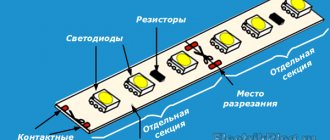
Types of three-color LEDs.
The way the device is controlled depends on the design of the LED.
Based on lens type, LEDs are:
- with transparent lens;
- with matte lens.
For RGB elements with a clear lens, additional light diffusers may be needed to achieve mixed shades. Otherwise, individual color components may be visible.
Connecting the Arduino button
Turning the LED on and off using a button
Let's start with the simplest way to connect a tact button. Consider a circuit with an Arduino as a power source, an LED, a 220 Ohm limiting resistor and a button that will close and open the circuit.
If you have a different type of switch, then you can safely select contacts from opposite corners (on some buttons there is a special mark in the form of a recess, by which you can determine which side the paired contacts are located on). The most reliable way to determine the correct legs is to ring the contacts with a tester.
The circuit itself with a button, LED and Arduino controller does not need any special explanation. The button breaks the circuit, the LED does not light up. When pressed, the circuit closes and the LED turns on. If you mix up the contacts (turn on the buttons through closed paired contacts), the button will not work because the circuit will never open. Just swap the contacts.
Connecting a button with a pull-up resistor
Let's now connect the button to the Arduino so that we can read its state in the sketch. To do this, we will use the following scheme.
In the sketch we will monitor the fact of pressing and display a message on the port monitor. We will give a more interesting example and a detailed explanation of the circuit itself a little later.
One thing to pay attention to is the 10K resistance we added in this circuit. We'll talk about its purpose in more detail later, just keep in mind that such a resistor is necessary for the circuit to work properly.
Sketch for an Arduino button with a pull-up resistor:
/* An example of using a clock button in Arduino. The button is connected to pin 2. */ const int PIN_BUTTON = 2; void setup() { Serial.begin(9600); pinMode(PIN_LED, OUTPUT); } void loop() { // Get the button state and display it in the port monitor int buttonState = digitalRead(PIN_BUTTON); Serial.println(buttonState); delay(50); }
Principle of operation
The operating principle of RGB LEDs is based on color mixing. Controlled ignition of one, two or three elements allows you to obtain a different glow.
Discrete color mixing palette.
Incorporating the crystals individually produces three corresponding colors. Paired inclusion allows you to achieve glow:
- red+green pn transitions will ultimately give yellow color;
- blue+green when mixed gives turquoise;
- red+blue makes purple.
Including all three elements produces white.
Much more possibilities are provided by mixing colors in different proportions. This can be done by separately controlling the brightness of each crystal. To do this, you need to individually regulate the current flowing through the LEDs.
Palette of mixing colors in different ratios
Analog and digital outputs on Arduino
If you want to regulate the output voltage, you should use the pins marked with the symbol “~”. For Arduino Uno, these are 3, 5, 6, 9, 10, 11. Using the analog ports, you can output any voltage from 0 to 5 Volts, and the digital outputs can only be turned on and off. Analog ports use PWM (pulse-width modulation), in English PWM (pulse-width modulation), with the help of which an analog signal is simulated.
The analog outputs on the Arduino board have, o
To understand the difference between a digital and analog signal, assemble a circuit using an LED and a resistor on a breadboard, as in the first lesson - Connecting an LED. But this time connect the LED to analog output ~9. Open the LED flashing sketch from the first lesson and change its output port from Pin13 to Pin9. Upload the sketch to your Arduino NANO or UNO board.
On Arduino, the analog output will work as digital
Port 9 can work as a digital output. But if the digitalWrite function is changed to analogWrite, then instead of the values HIGH (1) and LOW (0) you can set any value from 0 to 255. It is in this interval that you can change the voltage on the analog outputs. Download the program to smoothly turn on and fade out the LED. A detailed description of the operation of this program is given below in the explanation of the code.
Sketch. Arduino analog signal and LED
int light = 0; // initial brightness of the LED int fade = 5; // step of changing the brightness of the LED void setup() { pinMode(9, OUTPUT); // use Pin9 for output operation } void loop() { // set LED brightness to Pin9 analogWrite(9, svet); // change the brightness by adding the specified fade value in each cycle svet = svet + fade; // change the fade order at minimum and maximum brightness if (svet == 0 || svet == 255) { fade = -fade; } delay(20); // set a pause for the effect }
Explanations for the code:
- Function , where pin is the output port to which the signal is supplied, value is a value between 0 (completely off) and 255 (fully on), used to control the brightness of the LED or the speed of the electric motor using Pulse Width Modulation (PWM);
- The variable has an initial value of “0”; each time the loop is executed, the specified value is added to the value (in this sketch, fade = 5);
- When the variable reaches its maximum value of 255, it takes on a negative value of -5. Now, each time the loop is executed, -5 is added to the value, i.e. each time from is deducted .
- If we compare the work of the sketch with the graph of the quantization process located in the figure at the beginning of the article, then this is the quantization step, i.e. the amount by which the supplied voltage increases, and is the sampling step, i.e. the period of time over which the value changes.
Pros and cons of RGB LEDs
RGB LEDs have all the advantages of semiconductor light-emitting elements. These are low cost, high energy efficiency, long service life, etc. A distinctive advantage of three-color LEDs is the ability to obtain almost any shade of light in a simple way and at a low price, as well as dynamic color changes.
The main disadvantage of RGB LEDs is the inability to obtain pure white by mixing three colors. This will require seven shades (a rainbow can be used as an example - its seven colors are the result of the reverse process: the decomposition of visible light into its components). This imposes restrictions on the use of three-color lamps as lighting elements. To somewhat compensate for this unpleasant feature, the RGBW principle is used when creating LED strips. For each three-color LED, one white glow element is installed (due to the phosphor). But the cost of such a lighting device increases markedly. There are also RGBW LEDs. They have four crystals installed in their body - three to produce the original colors, the fourth to produce white; it emits light using a phosphor.
Connection diagram for RGBW version with additional contact.
Connection diagram for RGB LED strip 5m or 10m long
First, let's consider the option when you have a total length of LED backlighting of only 5m or 10m, that is, two solid strips connected in parallel, 5m each. What is needed in this case?
- power supply that converts 220V from the network into 12 or 24V necessary for the backlight to operate
All the nuances of its selection, voltage regulation and connection features can be found in the article “How to choose the right power supply for an LED strip.”
- RGB controller
Unlike the power supply, it can be selected without a power reserve, which is called back-to-back. The main thing is to correctly calculate the power of the tape itself.
For example, if 1m consumes 14.4W (data can be found on the packaging or from tables, according to the type of LED), then 10m will respectively “eat” 144W. This is the power you buy the controller for.
How to connect all this correctly? Firstly, 220V must be supplied to the power supply itself. Usually on the left there are two terminals marked L (phase), N (zero) and ground. Here the polarity of L and N is not necessary.
Next in the diagram is the controller. It has a number of terminals:
- Light with BGR V+ contacts
They stand for: B (blue) - blue
G (green) – green
R (red) – red
+V – common plus on the LED strip. Directly on the tape it can be signed as “+12” or simply “+”. All other three rgb pins are negative.
- Power with “+” and “-” contacts
Unlike monochrome tape, the RGB version has not two contacts, but four. And sometimes all five!
The fifth is responsible for white light, since normal white natural light cannot be obtained from a combination of RGB colors. These LED strips are called RGBW or RGBWW.
Therefore, check in advance how many contacts for soldering wires the tape has and buy the appropriate controller. This is especially true when shopping through online stores.
The Power contacts are supplied with 12 or 24V voltage from the power supply.
Here it is strictly necessary to observe polarity.
Look for terminals on the block labeled “V+” and “V-“. Instead of “V-“ they sometimes write “COM”.
Next, insert three wires soldered to the RGB strip into the controller terminals, each of which is responsible for its own color. Connect R to R, G to G and so on.
If you mix up the order, connect red to green or vice versa, nothing bad will happen, the colors on the control panel will just get confused.
By the way, in extreme cases, an RGB LED strip can be connected without a controller at all, directly to the unit.
To do this, you need to twist all three rgb wires into one and apply a minus wire to it, and a positive wire to the second one.
True, in this case, there can be no question of any multi-colored lighting. However, it can be considered as one of the lighting options if the controller fails.
If you correctly connect the RGB strip according to the first option, you should have the sequence: 1 Power supply 2 Controller 3 RGB LED strip
Life time
The service life of a device consisting of three crystals is determined by the time between failures of the shortest element. In this case, it is approximately the same for all three pn junctions. Manufacturers claim the service life of RGB elements at 25,000-30,000 hours. But this figure must be treated with caution. The declared life time is equivalent to continuous operation for 3-4 years. It is unlikely that any of the manufacturers conducted endurance tests (and even in various thermal and electrical modes) for such a long period. During this time, new technologies appear, tests must be started anew - and so on ad infinitum. The warranty period is much more informative. And it is 10,000-15,000 hours. Everything that follows is, at best, mathematical modeling, and at worst, naked marketing. The problem is that, as a rule, there is no manufacturer’s warranty information for common inexpensive LEDs. But you can focus on 10,000-15,000 hours and keep approximately the same amount in your head. And then you can only rely on luck. And one more point - the service life very much depends on the thermal conditions during operation. Therefore, the same element will last for different times under different conditions. To extend the life of LEDs, one must be attentive to the problem of heat removal, do not neglect radiators and create conditions for natural air circulation, and in some cases resort to forced ventilation.
But even reduced terms mean several years of operation (after all, LED will not work without pauses). Therefore, the emergence of three-color LEDs allows designers to widely use semiconductor devices in their ideas, and engineers to implement these ideas “in hardware.”