Source:
|
In everyday life, parallel connections of light bulbs are most often used, but sometimes a series connection is more profitable.
Due to the growing popularity of spotlights, there are more lighting fixtures in apartments and private homes.
If you need to replace a light bulb, there are no problems; adding additional light sources is more difficult.
If such work is carried out independently, the ability to determine the advantages of each type of connection and draw up diagrams is required.
Features and characteristics of lamp connection diagrams
The method and order of connecting the lamp depends on its type. The methods used for incandescent light bulbs will not work with halogens, fluorescent lights, or LEDs.
Parallel
When using a parallel connection circuit, light sources are connected to phase and neutral. For example, if you need to connect 2 light bulbs, their power wires are twisted. It is important that the cross-section matches the load. The voltage on all lamps is the same, they burn with the brightness set by the manufacturer. Burnout of a single element does not affect the functionality of the others.
Reference! In practice, if there are several light sources, the wires are not twisted when connected in parallel. A cable is used to which all elements are connected.
Parallel connection can be:
- beam - a separate cable for each lamp;
- loop - phase and zero first go to the first lighting device, then part of the cable goes to the rest (except for the last one, to which two parts are connected).
When using a parallel beam model, the burnout of one element does not interfere with the operation of the others. Before choosing a daisy chain model, it is necessary to take into account that disruption of one connection will damage the elements located after it. But the problem is solved quickly due to easy identification of the problem area.
When connecting halogen sources to a transformer, it is necessary to take into account that they are connected to the secondary winding of the converter through terminal blocks.
The main disadvantage of fluorescent lamps is flicker. Ballast control equipment eliminates this problem, but it is expensive. To reduce ripple, a special circuit is used for two lamps with a phase shift on one of them. Two light bulbs are connected in parallel, a phase-shifting capacitor is connected to one.
An example of calculating the connection of lamps of different power
To understand the differences, it is enough to know Ohm's law and other simple electrical laws.
Let there be an incandescent light bulb with a voltage of 220 volts. At a frequency of 50 Hz, it represents a purely active resistance, so it is more convenient to understand initial questions with it. If the lamp has a power of 100 watts, then when connected to the network, a current I=P/U=100 watts/220 volts=0.5 A (approximately enough for reasoning). The full network voltage of 220 volts will drop across it. You can calculate the resistance of the thread: R=U/I=220 volts /0.5 amperes =400 Ohms (approximately).
If you connect a second similar light bulb in parallel with the first, then it is obvious that the entire mains voltage will be applied to each lamp. The current consumption Ipot will branch into two streams and current I=U/R=220 volts/400 Ohm=0.5 amperes . The current consumed will be equal to the sum of the two currents (as Kirchhoff's first law says) and will be 1 A. As a result, both lamps will be under full mains voltage, the rated current will flow through them, and the total luminous flux will be equal to twice the flux of one lamp.
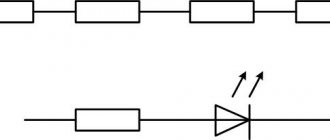
Parallel and series connection of light sources of equal power.
If two identical lamps are connected in series, the mains voltage will be divided between them, and each will drop about 110 volts. The total resistance of the circuit will become equal to Rtot = 400 + 400 = 800 Ohm , and the current through each lamp (with a series connection it is the same for each element) will be / 800 Ohm = 0.25 A. The result is:
- only half of the mains voltage drops on each lamp;
- a current flows through each lamp, reduced by 2 times from the rated one.
To estimate the luminous flux of incandescent lamps for a given case, you can use the Joule-Lenz law. Incandescent lamps glow by heating the filament. Over a period of time t, the thread will release the amount of heat Q=I2*R*t=U*I*t . The current will be halved, the voltage on one lamp will also be halved. This means we can expect a decrease in luminous flux by 2*2=4 times . For two lamps, the flux will decrease by half relative to one lamp in nominal mode. That is, when connected in series, two light bulbs will shine approximately twice as dim as one.
The problem can be solved by using lamps with an operating voltage two times lower than the mains voltage . If you use two hundred-watt light sources with a voltage of 127 volts, then 220 volts will be divided in half, and each lamp will operate in nominal mode, the luminous flux will double compared to one lamp of the same power. But this does not get rid of the main drawback of such a circuit - when one lighting fixture fails, the circuit breaks, and the second lamp also stops shining.
All of the above applies to lamps with the same power. If the power of the lamps differs markedly, then the following effects occur in the circuits. Let one 220-volt lamp have a power of 70 watts, the other 140.
Then the rated current of the first is I1=P/U=70/220=0.3 amperes (rounded), the second is I2=140/220=0.7 amperes . The filament resistance of the less powerful lamp is R1=U/I=220/0.3=700 ohms , the second - R2=220/0.7=300 ohms .
A lamp with a higher power corresponds to a lower filament resistance.
Parallel and series connection of light sources of various powers.
With a parallel connection, the voltage on both devices will be equal, and each lamp will have its own current. The total current consumption is equal to the sum of two currents Ipotr = 0.3 + 0.7 = 1 ampere. Each lamp operates in nominal mode and consumes its own current.
In a series connection, the current will be limited by the resistance Rtotal = 300 + 700 = 1000 Ohms and will be equal to I = U/R = 220/1000 = 0.2 A. The voltage will be distributed proportionally to the thread resistance (power). On a 140 watt lamp it will be 1/3 of 220 volts - approximately 70 volts. On a low-power lamp - 2/3 of 220 volts. That is, about 140 volts. Both lamps will shine at a low level due to a decrease in voltage and current, but the mode for them will be light. It’s another matter if lamps at half the mains voltage are used. On a lamp of lower power, the voltage will be higher than permissible, and the greater the difference in power, the greater the difference. This lamp will soon fail. And this is another disadvantage of connecting lamps in series. Therefore, such a connection is used extremely rarely in practice. An exception is the series connection of fluorescent lamps. It is believed that with this scheme they work more steadily.
Series connection of fluorescent light sources. The starters here are also rated at 127 volts.
To summarize the differences between parallel and serial connection:
- when connected in parallel, the voltage on all consumers is the same, the current is distributed in proportion to the power of the lamps (if the power is the same, then the currents will be equal), the total current consumption is equal to the sum of the currents of all lamps;
- with a series connection, the current through all lamps will be the same, it is determined by the total resistance of the circuit (and will be less than the current of the lowest-power lamp), the voltage across consumers will be distributed in proportion to the power of the lamps (if it is the same, then the voltages will be equal).
Using these principles, you can analyze the operation of any circuit.
Comparison of advantages and disadvantages of schemes
Advantages and disadvantages of daisy chain connection
| Lamp type | Advantages | Flaws |
| Incandescent, halogen, fluorescent | Extends service life Reduces flickering of fluorescent lamps | Voltage drop If one element fails, the rest do not work Light sources must have the same power |
| LED | The best option to ensure the same current on all sources | A large number of light bulbs require a high-power power source. If one element fails, the rest stop working. |
How to choose the right driver?
Everything is very simple here. You only need to choose according to three parameters:
- output current;
- maximum output voltage;
- minimum output voltage.
The output (operating) current of the LED driver is the most important characteristic. The current should be equal to the optimal current for LEDs.
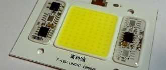
For example, we had at our disposal 10 pieces of full-spectrum LEDs for a phytolamp:
The rated current of these diodes is 700 mA (taken from the reference book). Therefore, we need a 700 mA current driver. Well, or a little less to extend the life of the LEDs.
The maximum output voltage of the driver must be greater than the total forward voltage of all LEDs. For our phytoLEDs, the forward voltage is in the range of 3...4 volts. We take it to the maximum: 4V x 10 = 40V. Our driver must be able to output at least 40 volts.
The minimum voltage, accordingly, is calculated based on the minimum value of the forward voltage on the LEDs. That is, it should be no more than 3V x 10 = 30 Volts. In other words, our driver must be able to reduce the output voltage to 30 volts (or lower).
Thus, we need to select a driver circuit designed for a current of 650 mA (let it be slightly less than the nominal one) and capable of outputting a voltage in the range from 30 to 40 volts as needed.
Therefore, for our purposes something like this will do:
Of course, when choosing a driver, the voltage range can always be expanded in any direction. For example, instead of a driver with a 30-40 V output, one that produces from 20 to 70 Volts is perfect.
Examples of drivers that are ideally compatible with various types of LEDs are given in the table:
| LEDs | What driver is needed |
| 60 mA, 0.2 W (smd, ) | |
| 150mA, 0.5W (smd, , ) | driver 150mA, 9-34V (you can simultaneously connect from 3 to 10 LEDs) |
| 300 mA, 1 W (smd, , 5730-1, LED 1W) | drivers 300mA, 3-64V (for 1-24 LEDs connected in series) |
| 700 mA, 3 W (led 3W, phyto-LEDs) | driver 700mA (for 6-10 LEDs) |
| 3000 mA, 10 Watt (XML2 T6) | driver 3A, 21-34V (for 7-10 LEDs) or see |
By the way, to connect the LEDs correctly, it is not at all necessary to buy a ready-made driver; you can simply take some suitable power supply (for example, a phone charger) and screw a simple current stabilizer to it on one transistor or on LM317.
Ready-made current stabilizer circuits for LEDs can be taken from this article.
Advantages and disadvantages of parallel connection
| Lamp type | Advantages | Flaws |
| Halogen incandescent, fluorescent | It is possible to connect any number of lamps to the network using a daisy chain circuit Burnout of a single element of the beam model does not affect the operation of the others Full glow on all bulbs You can connect a chandelier with several lamps Few connecting pins | Increased cost when using a beam circuit due to high cable consumption and the need for a terminal block. With a loop model, failure of one connection interferes with the operation of the others |
| LED | You can connect a certain number of diodes if their total power does not exceed the power of the power source. If a separate source burns out, the rest work | The circuit does not work if the diodes are connected through one resistor The design is bulky and expensive due to the large number of parts When a single element fails, the load on the others increases |
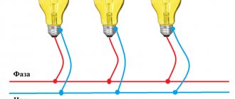
Parallel connection
Parallel connection of light bulbs
The classic parallel connection of lamps differs from the serial method in that in this case the full mains voltage is applied to all illuminators.
When connecting light bulbs in parallel, each branch has its own current flowing through it, depending on the resistance of the given chain.
The conductors supplied to lamp bases and sockets are connected to one wire in the form of a parallel assembly. The indisputable advantages of this method include the following features:
- if one of the bulbs burns out, the others continue to work;
- in each of the branches they burn at full power, since full voltage is applied to all at the same time;
- It is allowed to use energy-saving light bulbs;
- To connect to the network, it is enough to remove the required number of phase conductors from the room chandelier and arrange them in the form of a switched group.
This method has practically no disadvantages, with the exception of the high consumption of conductors in highly branched circuits. You can easily connect several light bulbs to one wire using the wiring principle. A typical circuit for connecting light bulbs in parallel with a switch is no different from conventional switching. In this case, a key switch is additionally introduced into it.
In which circuit will light bulbs of the same power shine brighter and why?
When using a series circuit, the voltage decreases as the number of elements increases. The light bulbs burn at full intensity or even less, since the voltage is divided evenly. The total power for a series connection of 2 elements of 100 W each is lower than that of one (the level of illumination is reduced).
When two lamps are connected in parallel, 220 V is supplied to each lamp, they operate at full heat. The total power increases by 2 times (the level of illumination increases).
Preparation of materials and parts
Preparation should begin with the choice of design and technology. You need to decide how to make a lamp from an LED strip with your own hands, decide on its shape, size and other parameters. Only after this will it be possible to calculate the amount of materials, decide on tools and other necessary elements. In any case, you will need:
- LED Strip Light;
- power unit;
- soldering iron;
- scissors;
- glue;
- insulating tape.
To make a lamp yourself, you will also need a support structure, a supporting element on which the LED strip will be attached. This issue must also be resolved in advance, at the design stage.
The shape of the lamp may be different. The peculiarity of the LED strip is its flexibility, the ability to be installed on both flat and curved surfaces. It is possible to create a suspended linear structure, wall or tabletop version.
Since you only need to install the LED strip on a specific support system, the main task becomes the choice of one or another type of structure or design. Most users make do with improvised materials, but there are also more complex products, when a chandelier is made from an LED strip, a lamp is made that resembles a separate light bulb, etc.
They also require starting parts or materials that must be prepared in advance. The shape or design of the supporting part is not of fundamental importance, but one rule must be taken into account: since the LED strip is sensitive to temperature, the supporting element must also be a radiator that effectively removes thermal energy. The best option is a homemade case made from massive metal parts, chrome-plated furniture pipes and other similar items.
What to do if there is no ready-made LED strip
The absence of an LED strip does not necessarily put an end to the whole idea. You can make it yourself using a certain number of ordinary LEDs. There can be many manufacturing methods; let’s consider the simplest and most convenient one. You will need:
- LEDs with operating voltage 3 V;
- strips of getinax or other less rigid plastic with good thermal conductivity;
- transparent heat shrink tube;
- plastic bottle, preferably green;
- wires, soldering iron and solder.
Procedure:
On strips of getinax 1 cm wide, holes are drilled along the entire length into which the LED housings will be inserted. The distance between centers is chosen so that the elements are evenly placed along the length and are not too far apart from each other (placement in 3 cm increments looks quite attractive). After installation, the contacts are connected to each other (if their length is not enough, they are extended with a thin wire), strips of plastic of the same width, cut from bottles, are laid on the front side of the strips
They act as a light filter and are good when using transparent (colorless) LEDs. Then they carefully stretch the transparent heat shrink and, carefully heating it, cover the resulting LED strip, providing high-quality protection from moisture. The resulting segments are connected into a group of 4 parallel elements so that a standard 12-volt source can be used.
All that remains is to connect the power supply and install the lamp in the designated place.
Application of both schemes in everyday life
The most popular products with a serial connection are garlands.
This model can be used for other purposes:
- make cheap lighting in a long corridor;
- save on the purchase of light bulbs due to frequent burnout by connecting additional ones;
- extend the life of light sources (if instead of one 60 W, connect 2 100 W).
Reference! Experienced electricians use this property to determine the phases in a three-phase network.
In workshops and garages, powerful incandescent or halogen lamps are used for heating. Two 1 kW elements are connected in series and placed in a metal container, which is installed on a brick. The temperature of such a heater is approximately 60°C. But you should take into account the minus - the lamps burn out very quickly.
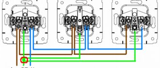
The parallel circuit is used in premises for any purpose (in lighting, chandeliers), and on the streets. It allows you to turn on individual light sources regardless of the operation of the others, just connect several switches. Usually, not only lamps, but also all electrical appliances in residential buildings are connected in parallel and connected to a 220 V household network.
A mixed model is often used to connect LED lamps. Several serial chains are created, which are connected to each other in parallel.
Soft start device (UPVL) for incandescent lamps 220V and 12V
Today, a large number of different UPVL models are produced, which differ in function, cost and quality. The device, which is sold in specialized stores, is connected in series to a 220 V light source. We can see the circuit and appearance of the device in the photo below.
Scheme of a soft switching device for 220 V lamps
If the power supply for the lamps is 12 or 24 V, then the device must be connected in front of the step-down transformer, also in series with the initial primary winding.
The device must correspond to the load that will be connected with a certain margin. To do this, you need to calculate the number of lamps and their total power.
Since the device is small in size, the UPVL can be placed under a chandelier, in a socket box or in a connection box.
Frequent errors when assembling a circuit and connecting a switch
An illiterate specialist most often enters zero into the switch instead of a phase. The lamps can work, but when turned off they will be energized, which is dangerous if the lamps need to be replaced.
Due to inexperience, both phase and zero are connected to the switch.
Important! Zero always goes to the lighting fixture.
The third mistake is connecting the supply wire to a tap instead of a common contact. As a result, only part of the chandelier works.
It happens that the neutral wire of the lighting device is connected not to the zero in the box, but to the phase.
To avoid mistakes with the switch, you should pay close attention to the wires. It is advisable to mark them before installing the switch in order to connect the same ones during the installation process.
Installation features
To correctly connect spotlights, you need not only to choose the right circuit. It is necessary to follow a certain sequence of actions, which depends on the type of ceiling.
You just need to connect a few spotlights - and you have a beautiful interior
In suspended ceilings
Spotlights are usually installed with suspended or suspended ceilings. If the ceilings are suspended, all wires are laid in advance. They are attached to the ceiling without connecting to power, the lamps are placed and secured on pendants, then the wires are connected to them and the operation is checked.
Prepared for installation of suspended ceilings
Before installing suspended ceilings, turn off the power, remove the lamps and remove parts that may be damaged by temperature. After installing suspended ceilings, holes are cut in the material (the lamps are visible or can be felt), sealing rings are installed, and then the lamps are assembled.
In plasterboard ceilings
If the ceiling is made of plasterboard, you can proceed according to the same scheme, but the lamps must be installed after the ceiling has been plastered. That is, separate the wiring and leave the ends of the wiring hanging freely. To avoid problems with determining the location of lighting fixtures, it is necessary to draw a detailed plan indicating the exact distances from the walls and from each other. According to this plan, markings are made and holes are cut out using a drill with a crown of the appropriate size. Since there may be small movements - a few centimeters - when cutting the cable, leave a margin of 15-20 cm. This will be quite enough (but do not forget that the wires are attached to the main ceiling and they should extend 7-10 cm beyond the level of the drywall. If the ends turn out to be too long, you can always shorten them, but extending them is a big problem.
If you need to install a converter
There is a second way to connect spotlights to a plasterboard ceiling. It is used if there are few light sources - four to six pieces. The entire installation of spotlights along with wiring is done after the work on the ceiling has been completed. Before installation begins, the cable/cables from the junction box are led beyond the ceiling level. After finishing the puttying and sanding work, markings are made and holes are drilled. The cable is passed through them, bringing the ends out. Then the lamps themselves are installed.
Everything is simple, but this method cannot be called correct: the cables simply lie on the drywall, which definitely does not comply with fire safety standards. You can still turn a blind eye to this if the ceiling is concrete, the cable is non-flammable, the cross-section of the wire is not small, and the connection of the wires is done correctly.
Sequence of work in photo format
If the floors are wooden, the PUE requires installation in non-flammable all-metal trays (cable ducts) or metal pipes. You can install such wiring only before starting work on the ceiling. It is very undesirable to violate installation rules - wood, electricity, heat generation during operation... not the safest combination.
How to phasing inputs with incandescent light bulbs
Phasing is performed if it is necessary to connect 2 three-phase inputs in parallel to the power source. The phases must not be mixed up to avoid creating an interphase short circuit.
Uses 2 incandescent lamps with a serial connection. One end of the wire is connected to the phase, the other needs to touch the remaining wires. If the phases are the same, the bulbs do not light up.
Important! You should not experiment in this way with one light bulb - it will immediately burn out in a 380 V network. Connecting two elements in series reduces the voltage by 2 times.
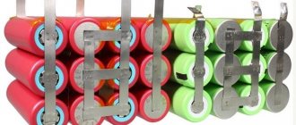
Mixed connection
The mixed type of connection is the most optimal. It is used in all LED strips, garlands, LED panels and is a mixture of parallel and serial connections.
So, not individual elements, but groups of LEDs are switched on in parallel. In groups, the diodes are connected in series through one resistor for each circuit.
Advantage:
- if an element from one chain breaks, the entire garland will continue to shine;
- You don't need many resistors.
This method takes into account and corrects all the shortcomings of parallel and serial connections.
Main conclusions
Some city apartment owners carry out renovations themselves. The process requires installation of new electrical wiring. To carry out this work, you need to be familiar with the basics of electrical engineering and be able to determine the optimal connection options, taking into account the features of the interior and the preferences of family members.
Although most electrical appliances in residential areas are connected in parallel, knowing how to connect light bulbs in series also helps. They will help if you want to arrange a cheap lighting system in the loft style or save on purchases.
When performing work independently, it is important to have knowledge about the types of wires, cables, switches, methods of connecting them, and areas of use. If you have neither knowledge nor experience, it is better to entrust the connection of light bulbs to a specialist.
How to connect 12 Volt lighting devices
When deciding how to connect ceiling lamps, similar circuits are used, the difference is as follows: the cable from the junction box goes to the switch, then goes to the converter, and from its output it is supplied to the lamps.
Read also: How to determine the value of a ceramic capacitor
When installing a large number of spotlights, it is recommended to divide them into two groups and connect them to a switch with two keys. Since the result is two branches, it is necessary to take two devices to reduce the voltage. You can use switches with three keys or install several single-key devices. Lighting over a wide range is provided using a dimmer.
A distinctive feature of the listed schemes is the presence or absence of an adapter. Otherwise, the solution to the question of how to make a spot light on the ceiling is no different.