Types of electrical conductor connections
The main connection schemes are parallel and serial connection. There are also combinations of these two inclusions.
Sequential
With a serial (in foreign terminology serial) connection, the terminals of the elements are connected so as to form a chain. One terminal of the device is connected to one adjacent link, and the second to another, on the opposite side.
Serial connection and practical application example.
An example of such a connection is the standard connection of an LED and a resistor. The resistor is needed as a current-limiting ballast.
Parallel
When connected in parallel, the same terminals of the circuit elements are connected to each other. A practical example is lamps in a multi-light chandelier or turn signal repeaters in a car.
Parallel connection and practical example.
Mixed
In one circuit, the connection diagram can be combined - serial + parallel. Some elements are connected in parallel, forming links. These links can be included in a sequential chain. Or vice versa - serial circuits are connected in parallel.
Combined connection of conductors.
This circuit is used, for example, in LED strips. In it, chains of current-limiting ballasts and radiating diodes are connected in parallel.
Symbols of electrical circuit elements
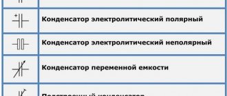
All elements of electrical circuits can be divided into active and passive. Active ones include current sources, batteries, and electric motors. Passive elements - connecting wires and electrical receivers (light bulb or other consumer). Their generally accepted symbols are intended to depict circuit elements in diagrams. Let's look at the main ones, since this information will be useful for further understanding the principles of connecting an electrical circuit using the example of wiring inside a house wiring.
Symbols of elements:
Designations of electrical circuit elements
How voltage, current and electrical power are calculated depending on the connection
Electrical circuit parameters are calculated differently depending on the type of connection. To figure out what the current strength will be passing through each resistance, you can use Kirchhoff's first law. One of its formulations states that the algebraic sum of currents flowing into a node is equal to the sum of currents flowing out of the node . The remaining dependencies will follow from this discussion.
In parallel connection
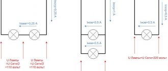
If we consider a parallel connection, for example, of three resistors, then we can note that the incoming current I in node 1 breaks up into three branches I1, I2, I3, and Kirchhoff claims that their sum is I1+ I2+ I3 = I. In node 2 all currents flow together into one current, and again I= I1+ I2+ I3.
A chain of three elements in parallel.
Obviously, the voltage across each resistor is the same and equal to U, therefore, according to Ohm’s law:
- I1=U/R1;
- I2=U/R2;
- I3=U/R3;
- I=U/Rtot.
From here U/Rtotal = U/R1+ U/R2+ U/R3, after reducing both parts by U, we obtain a formula for finding the total resistance when resistors are connected in parallel:
1/Rtot= 1/R1+ 1/R2+ 1/R3.
This formula is valid for any number of resistors, and its general form is 1/Rtot = 1/R1+ 1/R2+..+ 1/Rn, where n is the number of resistors in the assembly.
Parallel circuit of n elements.
It follows that with a parallel connection, the total resistance will be less than the smallest resistance in the set. When connecting two resistors, the formula takes the form Rtotal = R1* R2/(R1+ R2).
Also, from the equality I=U/R1+U/R2+U/R3 it follows that currents through parallel-connected resistors are distributed inversely proportional to their resistance values - the higher the resistance, the lower the current, and vice versa. If all resistors are of the same value, then the current flowing through each is found by dividing the total current by the number of resistances. If there are three elements in the assembly, then a third of the total current flows through each, and if n identical resistors are connected in parallel, then I/n flows through each.
Since the electrical power is equal to P=U*I, and the voltage across each resistor is equal, the power allocated to each element is distributed in proportion to the current and inversely proportional to the resistance of the resistor. If all the elements are the same, then the power will be dissipated on them the same.
For clarity, video.
For serial connection
If we consider a series circuit of three elements, we can see that the current flowing into node 1 will be equal to the flowing one. At node 2 the same relationship is fulfilled and so on ad infinitum.
Hence, the current strength in the series connection will be the same for any element and equal to I. The voltage applied to the circuit and equal to I * R will be distributed between the resistors:
U=U1+U2+U3=I*R1+I*R2+I*R3 = I* Rtot
After reducing by I, the total resistance of the circuit can be found. It is equal to the sum of the components, and the total resistance value will be higher than the resistance of any element:
Rtotal=R1+R2+R3
Obviously, the voltage drop in a series circuit is directly proportional to the resistance of each element - the higher the resistance, the higher the voltage across it . In the same way, these relations hold for a chain of n elements.
Since the currents are equal, the power will be distributed in proportion to the voltages, and therefore in direct proportion to the resistances.
Types of electrical wiring
Information about electrical circuit connections is closely intertwined with the topic of wiring and complements the methodology of electrical installation work. There are several types of wiring. However, before moving on to them, it is worth considering how wiring is formed in a private house:
- The power cable enters the building's distribution panel.
- The panel contains groups of automatic protection devices.
- Using automation and distribution buses, the cable is further divided into zones (consumer groups).
- The zones are divided into two groups: one is for sockets, the other is for lighting.
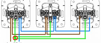
- The power cables of a separate zone enter the room, where they use their own wiring options. Thus, the power cable line going to the outlet can be connected to other outlets in a given room using the “loop” method, and the lighting line can be disconnected through a distribution box.
Types of electrical wiring connections:
| The star connection type (other names are boxless, or European) schematically looks like this: one socket - one cable line to the panel. That is, each socket and lighting point has a separate cable line, which goes directly into the panel and connects to a separate circuit breaker. The advantage of this technique is safety and the ability to control every electrical point. Also, with such wiring there is no need to install distribution boxes. The disadvantage of boxless connection is the increased wire consumption and, accordingly, increased labor costs for installing the system. |
| The “loop” is more economical compared to the “star”. You can depict a loop connection as follows: electrical panel or distribution box - socket - socket - socket. In other words, several electrical points are connected in series, and from them a common supply conductor goes either to the electrical panel or to the junction box. As you can see, this type of wiring connection is nothing more than a series connection in the context of an electrical circuit. |
| The most common type of wiring is using junction boxes. In this case, from the electrical panel, the power cable of a particular group branches out between consumers through distribution boxes, which are usually located above the switch near the entrance to the room. |
| Mixed wiring involves the simultaneous use of “star” and “loop” types in one system using distribution (junction) boxes. |
In their pure form, the listed types of disconnection are rarely used. As a rule, a mixed option is chosen. In this case, you must follow the rules for connecting the electrical circuit.
Examples of calculations
As practical examples, we can consider several options for calculating circuit parameters in different connection schemes.
For resistors
The simplest example of a calculation would be a chain of two resistances - 10 Ohms and 100 Ohms, connected in a chain. 12 volts are applied to the circuit.
A series circuit of two resistors.
First you need to find Rtotal, it is equal to the sum of R1 and R2. Rtot=100+10=110 Ohm. Hence the current in the circuit is I=U/R=12/110=0.109 amperes. The drop on each element can be calculated based on the equalities U1=I*R1 and U2=I*R2. Hence U1=1.1 V, and U2=10.9 V. Obviously, U1/U2=R1/R2. The first element will dissipate power P1=U1*I=1.1*0.109=0.12 watts (for practice, a standard component of 0.125 watts is suitable), and the second one will dissipate P2=U2*I=10.9*0.109=1 .19 watts (for practical implementation you will need a two-watt power supply).
If you connect these same two resistors in parallel and apply the same voltage, the parameters will be distributed differently.
Connecting elements in parallel.
First you need to determine Rtot=R1*R2/(R1+R2)=110*10/(110+10)=1100/120=9.17 Ohm (less than the smallest value of 10 Ohm). The total current will be I=U/Rtotal=12/9.17=1.31 amperes. Through the first element I1=U/R1=12/10=1.2 amperes will flow, through the second I2=U/R2=12/100=0.12. Obviously, I1+I2=I (taking into account rounding errors). The power required is:
- P1=I1*U=1.2*12=14.2 watts;
- P2=I2*U=0.12*12=1.42 watts.
If there is a mixed connection of elements, you must first convert the circuit to the same type - parallel or serial. Let there be a diagram of the following type.
Conversion of a mixed circuit.
In this case, it is convenient to replace the parallel assembly of R1 and R2 with a resistor with an equivalent resistance of R12, and R3 and R4 with R34. First, R12=R1*R2/(R1+R2)=9.17 Ohm is found. Using the same method, R34=150*5/(150+5)=4.8 Ohm is calculated. Then the total resistance of the equivalent circuit will be equal to R12+R34=9.17+4.8=13.97 Ohms.
Hence I=U/R=12/13.97=0.86 amperes. On the “garland” R1R2 the drop is U12=I*R12=0.86*9.17=7.87 volts, and on R3R4 the drop will be U34=I*R34=0.86*4.8=4.13 volts. Next, we need to return to the original circuit and consider separately the section of the R1R2 circuit with the found parameters.
Section of the circuit containing R1 and R2.
Hence I1=U/R1=7.87/10=0.787 amperes, I2=U/R2=7.87/100=0.0787 amperes. By power – P1=U*I1=7.87*0.787=6.2 watts, P2= U*I2=7.87*0.0787=0.62 watts.
The section containing the R3R4 elements is calculated in the same way.
Serial connection of energy receivers
Receivers of electrical energy can be connected to each other in three different ways: in series, in parallel or mixed (series - parallel). First, let's consider a sequential connection method, in which the end of one receiver is connected to the beginning of the second receiver, and the end of the second receiver is connected to the beginning of the third, and so on. The figure below shows the series connection of energy receivers with their connection to the energy source
An example of serial connection of energy receivers.
In this case, the circuit consists of three serial energy receivers with resistance R1, R2, R3 connected to an energy source with voltage U. An electric current of force I flows through the circuit, that is, the voltage at each resistance will be equal to the product of the current and resistance
Thus, the voltage drop across series-connected resistances is proportional to the values of these resistances.
From the above, the rule of equivalent series resistance follows, which states that series-connected resistances can be represented by an equivalent series resistance, the value of which is equal to the sum of series-connected resistances. This dependence is represented by the following relations
where R is the equivalent series resistance.
Questions
1. Which connection of conductors is called parallel? Draw it on the diagram. 2. Which electrical quantity is the same for all conductors connected in parallel? 3. How is the current strength in the circuit before its branching expressed through the current strengths in the individual branches of the branching? 4. How does the total resistance of the branch change after increasing the number of conductors in the branch? 5. What kind of conductor connection is used in residential premises? 6. What voltages are used for domestic needs?