What is a capacitor?
A capacitor consists of two conducting plates located very close to each other and separated by a dielectric. Applying a constant voltage to the plates will cause current to flow and the appearance on both covers of charges equal in magnitude, but opposite in sign: negative on one and positive on the other. Disabling the power source will result in the charge not disappearing instantly, ignoring the phenomenon of its gradual leakage. Then, if the part covers are connected to some kind of load, for example, to a flash, the capacitor will discharge itself and return all the energy accumulated in it to the flash.
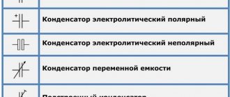
Capacitor designation
Capacitors are passive components that store electrical charge. This simple function is used in various cases:
- With alternating current.
- At constant current.
- In analog networks.
- In digital circuits.
Examples of using devices: synchronization systems, signal shaping, communications, filtering and signal smoothing, setting up televisions and radios.
Addiction
Thanks to the description given earlier, we learned what capacity is. Next, we will try to figure out what this characteristic depends on. The capacitance of the capacitor depends on the distance between the plates, their area, as well as on the dielectric material itself. Thanks to this, we can say what the capacitance of the device depends on: it is directly proportional to the area of the capacitor plate and inversely proportional to the distance between the plates.
Let's consider how to find this value. For a flat capacitor, the formula for calculating capacitance is as follows:
The dependence of the device’s ability to accumulate charge on the area of its plates and the thickness of the dielectric layer also indicates that this value is also influenced by the overall dimensions of the element.
Capacitor Characteristics
The main characteristic of this element is capacitance, or C. It determines the ability of the device to collect electrical charge, depends on the geometric configuration of the covers and on the electrical constant of the dielectric between the covers.
Important! The capacitance depends on the type of dielectric used, as well as on the geometric dimensions of the element.
In order to describe the principle of operation of the device with a formula, it is necessary to understand that this is a constant proportionality in the equation, which represents the mutual dependence of the accumulated charge q on the area of the plates and on the potential difference V between them.
You may be interested in this Transition from 380 to 220 volts
Power is expressed in units called farads F. But in practice smaller units such as microfarads and picofarads are also used.
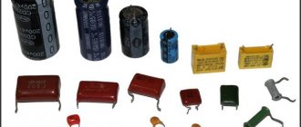
Appearance of devices
Thus, if a voltage U is applied to a capacitor, an electric charge accumulates on the caps of the part. The value of the accumulated charge on each plate is the same, they differ only in sign. This process of accumulation of electrical indicator is called charging.
Another parameter of the part is the rated voltage, namely, its maximum value that can be supplied to the capacitor. When a higher voltage is connected, dielectric breakdown occurs. This causes the element to short circuit. What the nominal voltage value will be depends on the type of dielectric and its thickness.
Important! The thicker the dielectric, the higher the rated voltage it can withstand.
Legend
Another parameter is the leakage current - the value of the conductive indicator that occurs when a constant voltage is applied to the ends of the element.
Parallel and combined connection
There are other connection methods, namely combined and parallel connection of capacitors. Other physical laws apply to them.
Parallel capacitors
Capacitor energy
The voltage of the entire group when connecting capacitors in parallel is equal to the voltage of the smallest of them. That is, if there is a circuit of three capacitors for 16, 25 and 50 V, then the maximum that can be applied to them is 16 V. In such a circuit, the full voltage of the power source will be applied to each individual capacitor.
The capacity of such a battery is cumulative. This is caused by the virtual addition of the areas of the plates of all individual capacitors. In the language of physics it looks like this:
Ctotal par = C1 + C2 + … + Cn.
Why is such a connection needed? It is used to increase the capacitance of capacitors, for example, in the high-voltage part of welding inverters and many powerful power supplies.
Additional Information. A parallel connection allows you to reduce the overall internal resistance of the assembly, and therefore its heating. This way you can increase the service life of the container.
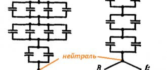
The combined (mixed) compound is the most complex. It contains both serial and parallel elements. Calculation of the parameters of such circuits is given with experience. For simplicity, it is customary to study it in a triangle, breaking it down into simpler parts.
Mixed compound
From the diagram it is obvious that capacitors C1 and C2 are connected in series. Their total capacity can be calculated using the formula described above - Ctotal last. Further the scheme is simplified. There are already two parallel capacitors Ctot.seq and C3. Calculated using the above formula Ctotal par. As a result, a difficult-to-understand circuit element turns into one equivalent capacitor. This technique describes a simplification algorithm with which you can calculate much more complex capacitor figures (square, cube, etc.).
What are capacitors used for?
Power plants
Almost all electronic devices have a power supply that converts the alternating current present in the home into direct current. Capacitors play an important role in converting alternating current to direct current, eliminating electrical noise. Energy sources use electrolytic capacitors of various sizes, from a few millimeters to several inches (or centimeters).
Sound coverings
Capacitors have many uses in audio equipment. They block DC input to the amplifier, preventing sudden sounds or noise that could damage speakers and headphones. These parts are used in audio filters to control the bass.
Computers
Digital circuits in computers transmit electronic pulses at high speeds. These network flows can interfere with signals from a nearby circuit, so high-tech equipment designers use capacitors to minimize interference.
High tech capacitor
How does a single-phase electric motor work?
Single-phase motor device
In fact, despite the name, 220V single-phase motors have two phases. However, due to the fact that only one phase directly works, they are called single-phase. The structure of the drive, in general, is not very different from any other engines. Its composition is as follows:
- A static element called a stator.
- A rotating element called a rotor.
A single-phase electric motor can be described as follows: it is an asynchronous electric drive, on the static element of which the working (main) winding is located. It is connected to a single-phase network with alternating electric current.
How to correctly calculate the capacitance of a capacitor?
The simplest example of a capacitor is a flat model. It has the shape of two parallel covers made of a conductor, between which there is a dielectric layer. In order to know how to calculate the capacitance of capacitors, you need to apply the following formula:
You might be interested in: Features of megawatts and kilowatts
C = ex e0 xs / d,
where S is the surface area of the plates and d is the distance between them. In turn, this is the relative electrical permittivity of a given dielectric.
As a rule, capacitors are not used individually, but are connected to larger systems. They can be connected in series, parallel or mixed.
Capacity formula
Important! In series-connected elements, the absolute value of the charge on each plate is identical.
Thus, the resulting voltage is equal to the sum of these indicators on the individual components of the device.
The total capacity of the system will be determined by the formula:
1/С = 1/С1 + 1/С2 + 1/С3 + …
When connected in parallel, the potential difference on each part is the same. Thus, the total charge will be equal to the sum of the charges on the components of the capacitor, and the resulting capacitance will be equal to the sum of the individual unit values:
C = c1 + c2 + c3 + …
Variable capacitors
Capacitor energy
Initially, people had enough of the capacitors described above from a pair of plates. Then this device was developed. Devices in the form of balls, disks and cylinders began to appear. This was necessary in order to increase the capacitance of the capacitor C, because it is primarily related to the area of the plates S and the distance between them d. This is clearly seen from the formula. It is used to calculate the capacitance of the capacitor.
Capacitor capacity
Over time, these non-standard geometric shapes ceased to satisfy the needs of experimenters. Therefore, new devices with variable capacity were developed. They have movable plates. This allows you to easily change the area of their mutual intersection, thereby affecting the value of the capacitance of the capacitor. The most common and familiar example of this electronic device is the oscillatory circuit in the radio. All people have adjusted the receiver at least once. It is this “twist” that is a variable capacitor. When it rotates, the capacitance changes, and accordingly, the resonant frequency of the oscillatory circuit of the radio receiver changes. This in turn tunes the radio to a different station.
Appearance of a variable capacitor
Basic formulas for capacity
The basic calculation of a capacitor involves identifying the relationship between the capacitance and the charge held on the element, as well as the voltage on the plates.
C=QVC=QV
C – capacitance, or volume in Farads Q – charge held on the plates in coulombs V – potential difference between the plates in volts
This equation is used to calculate the work required to charge the capacitor and the energy stored in it.
Energy formula
W=∫Q0V dQW=∫0QV dQ
W=∫Q0qC dQW=∫0QqC dQ
W=12CV2
Important! It is necessary to know what effect a capacitor will have on any circuit in which it operates. It not only prevents the passage of the DC component of the signal current, but also affects any AC signal.
Reactance
In a DC circuit, in addition to the battery, there may be a resistor that resists the current in the circuit. The same is true for an alternating current circuit with a charge-storing element. A capacitor with a small plate area allows only a small amount of charge to be stored, and this will prevent current from flowing. A capacitor has a certain reactance, and it depends on its value, as well as on the operating frequency. The higher the frequency, the lower the reactance.
You may be interested in this Features of the ripple coefficient
The actual reactance can be calculated using the formula:
Xc = 1 / (2 pi f C)
Where
Xc – capacitive reactance in Ohms. f – frequency in Hertz. C is the capacitance in Farads.
Current calculation
The reactance of a capacitor, calculated using the above formula, is measured in Ohms. The current flowing in the circuit can then be calculated in the usual way using Ohm's law:
V = I Xc
Main capacitor indicator
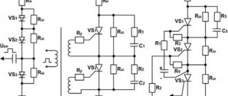
Connecting capacitors into a battery: methods of execution
There are 3 connection methods, each of which has its own specific purpose:
- Parallel - performed if it is necessary to increase the capacity while leaving the voltage at the same level.
- Consistent - the opposite effect. The voltage increases, the capacitance decreases.
- Mixed - both capacity and voltage increase.
Now let's look at each of the methods in more detail.
Parallel connection: diagrams, rules
It's actually quite simple. With a parallel connection, the calculation of the total capacitance can be calculated by simply adding all the capacitors. The final formula will look like this: Total = С₁ + С₂ + С₃ + … + Сn. In this case, the voltage on each of their elements will remain unchanged: Vtotal = V₁ = V₂ = V₃ = … = Vn.
It turns out that such an installation involves connecting all the capacitor plates to the power points. This method is the most common. But a situation may arise where it is important to increase the voltage. Let's figure out how to do this.
Serial connection: less commonly used method
When using the method of connecting capacitors in series, the voltage in the circuit increases. It consists of the voltage of all elements and looks like this: Vtot = V₁ + V₂ + V₃ +…+ Vn. In this case, the capacity changes in inverse proportion: 1/Comt = 1/С₁ + 1/С₂ + 1/С₃ + … + 1/Сn. Let's look at changes in capacitance and voltage when connected in series using an example.
Given: 3 capacitors with a voltage of 150 V and a capacity of 300 μF. Connecting them in series, we get:
- voltage: 150 + 150 + 150 = 450 V;
- capacity: 1/300 + 1/300 + 1/300 = 1/C = 299 uF.
This connection is made if there is a risk of breakdown of the capacitor dielectric when voltage is applied to the circuit. But there is another way of installation.
Good to know! Series and parallel connections of resistors and capacitors are also used. This is done in order to reduce the voltage supplied to the capacitor and prevent its breakdown. However, it should be borne in mind that the voltage must be sufficient to operate the device itself.
Mixed connection of capacitors: diagram, reasons for the need for use
This connection (also called series-parallel) is used if it is necessary to increase both capacity and voltage. Here, calculating the general parameters is a little more complicated, but not so much that it is impossible for a novice radio amateur to figure it out.
Let's create a calculation algorithm.
- the entire circuit needs to be divided into separate parts, the parameters of which are easy to calculate;
- calculate denominations;
- We calculate the general indicators, as with sequential switching.
Active and reactive resistance
Although active and reactance are very similar. Even the values of both parameters are measured in Ohms, but they are not exactly the same. As a result, it is impossible to add them together directly. Instead, they need to be summed “vectorically”. In other words, you need to round each value and then add them together and take the square root of that number:
Xtot2 = Xc2 + R2
This article described in detail the main components, structure and operating principle of capacitors, and also provided basic formulas designed to calculate the useful volume of the device. For a deeper understanding, it is necessary to carefully consider the types of these parts and their practical features in various circuits and devices.
Selecting a capacitor for a single-phase motor
The calculation of capacitor capacity for a three-phase asynchronous motor is carried out using the rated current (I), which is usually indicated on the motor nameplate, the phase voltage (U), and the coefficient (k). It will be equal to the value of 4800 for windings connected in a star circuit, and 2800 for windings connected in a delta circuit. Capacity is calculated using the following formula:
C = k*I / U
Although, if you need to calculate the capacitor capacity faster, you can use an online calculator. The resulting capacitance value is subsequently used to select a capacitor for a three-phase motor. What about the capacitor capacity for a single-phase motor?
We all know that motors that are designed to operate in a single-phase network are usually connected to 220 V. Only now, if the inclusion of a three-phase motor is determined by the location of the coils and the phase displacement of the network, then a single-phase motor requires the creation of torque to force the rotor to come into movement. For this, an additional starting winding is needed. And the phases of the current are shifted thanks to the capacitor.