Capacitors have found very wide application in electronics and electrical engineering in our time, because they are the main elements of most electrical circuits and circuits. In this article we will try to explain in detail what the electrical capacity of a capacitor is. The calculation formulas used will also be given, various types of such devices will be described and their markings will be discussed. In addition, the influence of various factors on the capacitance of the capacitor will be affected.
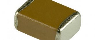
Capacitor
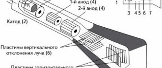
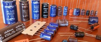
Before you figure out what the capacity of a simple capacitor is, you need to decide what this electrical element is. A capacitor is a radio-electronic part that can accumulate and release a certain portion of electrical charge. The device consists of the following elements:
- Cases. Often made of aluminum. It can be flat, spherical or cylindrical in shape.
- Covers (2 or more). They are made from metal plates or foil.
- Dielectric gasket. It is installed between the plates and serves as an insulator.
- Two or more output contacts for connecting the device to an electrical circuit.
This type of electric charge storage device works as follows.
- When an element is connected to a source of electric current, it acts as a conductor. At this moment, the electric current is at its maximum value and the voltage is at its minimum.
- Positive and negative charges (electrons and ions) begin to accumulate on the plates of the element. This way the device itself is charged. At the time of charging, the strength of the electric current gradually decreases, and the voltage, on the contrary, increases.
- After the amount of charge in the capacitor exceeds the permissible limit, it is discharged and the process begins to repeat cyclically again.
The basis for the performance of this device is its capacity. It is this parameter that determines the charge accumulation time and the total “capacity” of the device. The following figure below will help you understand how the simplest capacitor is indicated on the diagrams.
Electric capacitance, like the capacitors themselves, have found a wide range of applications. They are used as:
- Frequency filters.
- Pulse source for various photographic equipment.
- Smoothers of pulsating currents in rectifiers.
- Phase shifting elements for electric motors.
The use of capacitors in various fields is based precisely on the ability of the device to accumulate electrical charge. In more complex electrical equipment, these devices are used to uninterruptedly maintain a certain voltage in different data storage devices.
Capacity
The capacitance of a capacitor is a physical quantity that determines the relationship between the accumulated charge on the plates and the potential difference between them.
In the SI system, the capacitance of a capacitor and its unit of measurement is Farad. In formulas, the letter Ф (F) is used to denote it. However, capacitor capacitance is rarely measured in Farads because it is quite a large value. Most often, its multiples and submultiples are used.
The value of the electrical capacitance of a capacitor can always be found in the device markings, which are printed on its body.
In the diagram, the element is designated by the letter “C”. The designation of the capacity is a prerequisite, because this will simplify the process of selecting the necessary electrical components for the circuit.
What determines the capacitance and charge of a capacitor?
The capacitance of a capacitor is a physical quantity by which its ability to perform its functional tasks is assessed.
The practical value of capacitance is expressed in the ability of an electrical device to accumulate charge.
The voltage on the plates directly affects the quantitative characteristics of the charge on the plates. The formula for determining capacity looks like
C = q/U,
where C is the capacitance of the capacitor,
q - means the amount of charge on one of the plates,
U is the potential difference on the plates. The given calculation formula is largely theoretical in nature.
There is another definition of capacity, which is more useful in a practical sense.
The formula C = єS/d indicates its relationship with the area S of the plates, the distance between the plates d and the properties of the dielectric є.
It follows from the formula that the larger the area of the plates, the greater the charge that can be placed on them and the greater the distance between the plates, the weaker the charged particles will be attracted to each other, increasing their chances of leaving the plate.
The maximum dielectric constant of the material located between the plates increases the capacitance of the capacitor without changing the overall characteristics.
Addiction
Thanks to the description given earlier, we learned what capacity is. Next, we will try to figure out what this characteristic depends on. The capacitance of the capacitor depends on the distance between the plates, their area, as well as on the dielectric material itself. Thanks to this, we can say what the capacitance of the device depends on: it is directly proportional to the area of the capacitor plate and inversely proportional to the distance between the plates.
Let's consider how to find this value. For a flat capacitor, the formula for calculating capacitance is as follows:
The dependence of the device’s ability to accumulate charge on the area of its plates and the thickness of the dielectric layer also indicates that this value is also influenced by the overall dimensions of the element.
Calculation of capacitor capacity
In practice, capacitors consisting of two flat conductors (plates) separated by a dielectric are most often used as elements with a normalized electrical capacitance. The formula for calculating the electrical capacitance of such a capacitor looks like this:
C=(S/d)*ε*ε0
Where:
- C – capacity, F;
- S – area of coverings, sq.m;
- d – distance between plates, m;
- ε0 – electrical constant, constant, 8.854*10−12 F/m;
- ε – electrical permittivity of the dielectric, dimensionless quantity.
From here it is easy to understand that the capacitance is directly proportional to the area of the plates and inversely proportional to the distance between the conductors. The capacity is also affected by the material used to separate the plates.
Calculation
Calculation of the capacitance of the capacitor is done using a fairly simple formula:
In this formula:
- q is the amount of charge accumulated by the capacitor.
- φ1−φ2 is the potential difference between its plates.
This expression helps to quite easily calculate the capacitance of any flat-plate capacitor. As mentioned earlier in the article, this value of the electrical capacity of capacitors always depends on its geometric dimensions.
Flat capacitor
A distinctive feature of a flat-plate capacitor is the presence of two parallel plates. Such devices can have a square, round or rectangular shape.
Let us next consider how to determine the capacitance of this type of capacitor. The following formula will always help you find the capacitance of this type of capacitor:
Electrical capacity
Often, the use of capacitors involves connecting several such elements into a circuit at once. Thanks to this, the total capacity can be increased. The formula for determining the electrical capacity of a flat capacitor when connected in parallel is as follows:
Determining the total capacitance for such an electrical circuit is done as follows: C=C1+C2
The amount of charge and voltage for such a connection circuit is determined as follows:
qtot=q1+q2
Utot=U1=U2
The formula will allow you to determine the capacitance of a capacitor for a series connection of elements:
That is, in this case, the total electrical capacity of a flat capacitor is found using the expression:
1/Ctot=1/C1+1/C1
Using these expressions, we will find the total voltage and determine the amount of charge for a series connection of elements:
qtotal=q1=q2
Utot=U1+U2
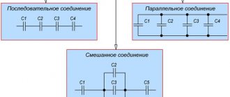
The capacitance of the capacitor and the calculation formulas used for various connection options for flat devices are shown in the figure below. We can say that it is very visual and easy to use:
Spherical capacitor
The spherical device has two plates in the form of concentric spheres, between which a dielectric is located. The capacitance of a spherical capacitor can be determined as follows:
In this expression, the value “4π” determines the coefficient of charge dissipation on the surface of spherical planes.
The capacitance of a spherical capacitor can be calculated using the formula for a flat device if the gap is quite small compared to the radius of the sphere.
Cylindrical
The cylindrical device is slightly similar to the previously described spherical one. They use similar-shaped linings. They also have a round shape, which means that the calculation of the capacity of a cylindrical device will also be influenced by such a parameter as the radius of the plates. The difference lies only in the most elongated shape of the plates of the cylindrical capacitor. The capacity of a cylindrical capacitor is determined by the formula:
Spherical and cylindrical types of elements are highly dependent on the thickness of the dielectric layer. The thicker it is, the smaller the charge volume will be, which means its resistance to breakdown voltage will increase.
Capacitor connection diagrams - capacitance calculation
To bookmarks
This article provides various diagrams for connecting capacitors, as well as formulas for calculating them with an example.
Series connection of capacitors
If we conditionally divide the terminals of each capacitor into the first and second terminals, the series connection of the capacitors will be performed as follows: the second terminal of the first capacitor is connected to the first terminal of the second capacitor, the second terminal of the second capacitor is connected to the first terminal of the third, and so on. Thus, we get a group (block) of series-connected capacitors with two free terminals - the first terminal of the first capacitor in the block and the second terminal of the last capacitor, through which this capacitor block is connected to the electrical circuit.
The series connection diagram of capacitors will look like this:
In fact, the series connection of capacitors is as follows:
With this connection scheme, the charges on the capacitors will be the same:
Qtot=Q1=Q2=Q3,
where: Q1, Q2, Q3 - respectively the charge on the first, second, third, etc. capacitors
The voltage on each capacitor with this circuit depends on its capacitance:
U1=Q/C1; U2=Q/C2; U3=Q/C3, where:
- U1, U2, U3 - respectively, the voltage on the first, second, third capacitors
- C1, C2, C3 - respectively, the capacitance of the first, second, third capacitors
In this case, the total voltage will be:
Utot=U1+U2+U3+…+Un
The total capacitance of capacitors in a series connection can be calculated using the following formulas:
- When connecting two capacitors in series:
Comm=(C1*C2)/(C1+C2)
- When three or more capacitors are connected in series:
1/Comm=1/C1+1/C2+1/C3+…+1/Cn
Parallel connection of capacitors
If we conditionally divide the terminals of each capacitor into the first and second terminals, the parallel connection of the capacitors will be performed as follows: the first terminals of all capacitors are connected to one common point (conditionally - point No. 1) the second terminals of all capacitors are connected to another common point (conventionally - point No. 2). The result is a group (block) of parallel-connected capacitors, the connection of which to the electrical circuit is made through conditional points No. 1 and No. 2.
The parallel connection diagram of capacitors will look like this:
Thus, the parallel connection of capacitors will look like this:
With this circuit, the voltage on all capacitors will be the same:
U=U1=U2=U3
The charge on each capacitor will depend on its capacity:
Q1=U*C1; Q2=U*C2; Q3=U*C3
In this case, the total charge of the circuit will be equal to the sum of the charges of all parallel connected capacitors:
Qtot=Q1+Q2+Q3…+…Qn.
The total capacitance of capacitors in a parallel connection can be calculated using the following formula:
Commun=C1+C2+C3+…+Cn
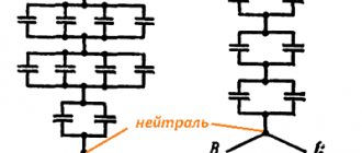
Mixed connection of capacitors
A circuit in which there are two or more groups (blocks) of capacitors with different connection patterns is called a mixed connection circuit of capacitors.
Here is an example of such a diagram:
For calculations, such circuits are conditionally divided into groups of identically connected capacitors, after which calculations are carried out for each group according to the formulas given above.
For clarity, we give an example of calculating the total capacity of this circuit.
Calculation example
Conditionally dividing the diagram into groups, we get the following:
As can be seen from the diagram, at the first stage we identified 3 groups (blocks) of capacitors, with the capacitors in the first and second groups connected in series, and the capacitors in the third group in parallel.
Let's calculate each group:
- Group 1 - series connection of three capacitors:
1/C1,2,3 = 1/C1+1/C2+1/C3 = 1/5+1/15+1/10=0.2+0.067+0.1 = 0.367 → C1,2,3 = 1/0.367 = 2.72 µF
- Group 2 - series connection of two capacitors:
C4.5 = (C4*C5)/(C4+C5)= (20*30)/(20+30) = 600/50 = 12 µF
- Group 3 - parallel connection of three capacitors:
C6,7,8 = C6+C7+C8 = 5+25+30 = 60 µF
As a result of the calculation, the scheme is simplified:
As you can see in the simplified diagram, there remains one more group of two parallel-connected capacitors; let’s calculate its capacitance:
- Group 4 - parallel connection of two groups of capacitors:
C1,2,3,4,5 = C1,2,3+C4,5 = 2.72+12 = 14.72 µF
Ultimately, we get a simple circuit of two series-connected groups of capacitors:
Now you can determine the total capacity of the circuit:
Total = (C1,2,3,4,5*C6,7,8)/(C1,2,3,4,5+C6,7,8) = 14.72*60/14.72+60 = 883.2/74.72 = 11.8 µF
Was this article useful to you? Or maybe you still have questions ? Write in the comments!
Didn’t find an article on the website on a topic that interests you regarding electrical engineering? Write to us here. We will definitely answer you.
↑ Up
5
https://elektroshkola.ru/elektrotexnicheskie-raschety/sxemy-soedineniya-kondensatorov-raschet-emkosti/
Examination
As noted earlier, the capacity of the device is marked on its body. You can check the rated value and the available capacity of the device using a tester with the “CX” mode. For example, the popular models M890D, AM-1083, DT9205A, UT139C, and others are suitable for this. Next you will need:
- Unsolder and discharge the device. Discharge is carried out with a strictly insulated metal object.
- Insert the legs of the capacitor into the grooves “CX”, observing the polarity.
- The device will display the measurement result on the display. It will need to be compared with the one indicated in the markings on its body. If the values differ greatly from each other, this indicates that the element is faulty and requires replacement.
If the multimeter shows the presence of infinite capacity, then this indicates a short circuit inside the device body and it is also considered faulty and requires replacement. In addition, the malfunction can always be determined visually by cracks or swelling of the housing.