Cable testing using a handset or headset
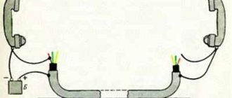
Since ancient times, wire testing has been carried out by two installers, each of whom was equipped with a handset or headset. One of them connected a source (battery or generator) to the line to power the microphones of the test tubes with a voltage of 12 - 100 V as shown in the figure.
1 — box type BKT; 2 - screw for fastening the plinth, communicating with the cable screen; 3 - screen wire; 4 - bundles of cable cores; 5 - braid with ringed pairs
Rice. 1 Cable testing using test handsets and a 12 - 100 V generator
One of the source terminals was connected directly to the cable screen, the other, through the test tube of one of the installers, was connected to a copper pair or group of pairs that needed to be identified at the return end. The second installer connected one of the terminals of the telephone handset to the cable screen, while the other one touched the cable cores one by one. The identification of the required pair was indicated by a click that was heard in the lineman's telephone receiver after it came under voltage. This also created a voice communication channel between the installers. Moreover, to organize voice communication during pair identification, it was enough for the second installer to short-circuit all the wires with each other and connect to them with the free terminal of the handset. The main disadvantages of the tubes are the poor audibility of clicks, the need to physically connect to the cable, as well as the inconvenience of work: the installer has to press the tube to his ear, and at the same time connect to different wires with his hands.
• Telephone
.
Concept and history • Basic components of a telephone set • Diagram and description of the operation of a telephone set • Dialing:
definition and types
⇒ Cable line testing with telephone handsets
•
Fiber testing
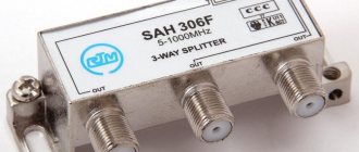
• OB testing using measuring instruments • Fiber optic couplers-clothespins
Dial cable line using telephone handsets
Checking the cable line with fitter tubes or continuity testing
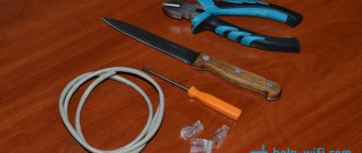
Fitter's telephone receiver. Portable telephone device.
This device can hardly be called a device or even a tool. However, telephone operators use it to identify almost all damage to cable and wire communication lines. It is used everywhere and is a mandatory attribute of the profession of a connected electrician. The presence of this thing in a person’s hands, as a rule, allows ordinary people to identify him as a signalman without any identification. We are talking about the telephone operator's handset.
Official name: portable telephone
. Currently, they are produced by industry and can have many different functions, but further we will talk about homemade products that are widespread in communications.
As a rule, it is made on the basis of a handset from an old rotary telephone. On the inside, between the microphone and the telephone capsule, a disk dialer from the same device is attached with screws or bolts. The type, color and other attributes depend on the capabilities of the installer or workshop that produces it. All this: microphone, telephone, dialer, are connected in series. Moreover, the disk dialer is connected in such a way that the counting contacts repeatedly open the circuit at the moment of the reverse motion of the disk, thereby ensuring dialing.
Fig.1. Telephone handset diagram.
Enlarge photo, more details
In construction organizations, they often use tubes without a dialer (photo on the right), because there it is used only for dialing. In operation, on the contrary, a handset without the ability to dial a number is useless.
It is advisable to use an old carbon microphone in the handset, not an electronic one. A telephone capsule, on the contrary, is better to take a modern, louder one. A correctly assembled handset, when connected to a telephone pair of wires, should cause a response from the station; a dial tone is heard in the telephone capsule. The number should be dialed accordingly. Usually, homemade work is not complicated by contacts that block the phone while dialing a number, so loud clicks are heard in the handset when dialing a number. Two cords coming out of the tube end in crocodile clips.
You can use this device with a battery of batteries, preferably more than 12 volts, switched on in series, but in operation they often use station power (“-” taken from a telephone pair). The search is simple: one wire of the cord is grounded, the second one sequentially touches the contacts on the plinth. A loud click in the tube is used to determine nutrition. Actually, all damage is determined by the volume of the click, that is, by ear.
Message
determined by connecting one contact to ground. The second one touches the line being tested. Naturally, the station power is turned off. If the click is loud, it means there is extraneous voltage on the wire, that is, a message.
Earth
determined by connecting one wire to the power supply. The second one touches the wire being tested. A loud click indicates reduced insulation on that wire. The complete absence of a click indicates the absence of capacitance, that is, an imminent wire break. The click should be barely audible, but it should be there.
A short
they recognize the same as the ground, while the second wire of the pair being tested is grounded.
Using this device, you can use the phone number to find the desired pair in the distribution cabinet, call anywhere from it, or eavesdrop on someone’s conversation, but this is already a crime and there is no advice on this topic on this site.
Continuity when installing a cable line.
Continuity during installation
cable line is described in the “Manual...” on the page Installation of prefabricated couplings.
→ → Call protocol forms
cable from the “Unified Guide...”
You can ring the cable without a microphone in the handset: read “If the microphone in the handset has shorted.”
Continuity when checking an installed cable line
Two tubes and some kind of power are used to test the cable. That is, to check the integrity of the cores and their correct installation or to select cable pairs during assembly. When dialing, the tubes are connected according to the following schemes:
Fig. 2. Scheme for checking the cable installation (continuity) of the cable with the battery through the “ground”
Fig.3. Scheme for checking cable installation (continuity) of a cable with station power via ground
Regarding the ““-” taken from the telephone pair,” the minus in this diagram and at the same time about the polarity of the station power supply, there is a page from the “Question and Answer” section Voltages on a wired/landline/home telephone set under different operating modes
Fig.4. It is possible to switch on not through the ground, but through the cable shield. Additionally, the integrity of the screen is checked
There are generally accepted two sequences of calling: “in pairs” or “in a row.”
In pairs.
The first installer touches the tube contact to 2 wires of the pair at the same time. The second one checks for the presence of “click” voltage on both cores of its plinth. Next, having made sure that both wires reach, the second one gives the command to the first one through the tube: “one”. The first installer switches to core “a”. The second one checks for the presence of a click on core “a” and its absence on the second core “b”, that is, it checks the pair for a short circuit. Then he gives the command to the first one: “further.” The first one switches to 2 wires of the next pair. The process is repeated.
Poreously.
The first concerns only the “a” core of the pair. The second one checks core “a” for a “click” and core “b” for its absence. He returns to core “a” and gives the command “further”. The first one switches to core “b”. The second one checks its presence on this vein and gives the command “further” using it. The process is repeated for the next pair.
From the outside, the dialogue between the installers can be heard either as “one, further, one, further...”. Or: “further, further, further...”.
Such a continuity test allows you to make sure that the installation is correct and that there are no wire breaks or “grounds” on these wires. But it does not guarantee verification of the absence of messages, as well as breakdowns (various parks) collected by dialing. According to the rules, messages and breakdowns should be determined during further measurements (with alternating current or on a working capacitance), but this often depends on the capabilities or integrity of the meters.
→ → Call protocol forms
cable from the “Unified Guide...”
Selecting a measurement method based on the nature of cable damage
Test to determine the nature of the damage
When it comes to cable damage, continuity becomes more difficult. In a damaged cable, it is advisable to find out exactly which core is connected, and which is broken. Therefore, here it is necessary not only to check each pair for short, but also to “click” all other cable pairs for a message. It is useful for the tester to know the whole picture of the damage in order to correctly determine the methods and conductors for measurements.
In practice, in the event of an incomplete cable break, as well as when the coupling leaks, it rarely happens that all the cores are “grounded” or communicated in the same way. Typically, the damage picture looks schematically like this:
Fig.5. Diagram explaining the electrical nature of cable damage
Analyzing this picture, you can, for example, notice that the “a” of the 1st pair lived in a cliff. For it, as well as for cores “b” of the second and third pairs (5 kOhm), the pulse measurement method is suitable.
Core “b” of the first pair is practically “clean”, that is, it can be used for measurements using bridge methods. For example, by short-circuiting cores 2b, 3b and 1b on side “B”, you can apply the Murray method (theory) (PKP-5) (for IRK-PRO “leakage”). Connect core 1b to the 1st terminal of the device (for IRK-PRO class A). The ratio of the insulation of a “clean” core to a damaged one will in this case be 4000/5=800, which is quite satisfactory for this method.
In the absence of such capabilities, you can even use core 4b (34 kOhm), but for the Kupfmüller method (PKP-5) (K coefficient for IRK-PRO), the error in this case will be greater, but it will already be possible to navigate the route.
And finally, to turn on the generator (contact search method), it is better to use a core with the least insulation, in this case, or, as usual, a cable shield (4 kOhm)
Solving such problems often resembles solving a rebus, and the more the meter knows and uses measurement methods, the less likely it is to make an error. Do not rush to connect the generator without deciding on the search area. As it was said in the famous cartoon, “ It’s better to lose an hour, but then fly in 5 minutes.”
»
There is a small page on this topic about my first cable damage.
• Telephone
.
Concept and history • Basic components of a telephone set • Diagram and description of the operation of a telephone set • Dialing:
definition and types
⇒ Cable line testing with telephone handsets
•
Fiber testing
• OB testing using measuring instruments • Fiber optic couplers-clothespins
What is a cable continuity test kit?
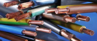
With the passage of time and the development of technology, specialized devices for testing cable pairs - test kits - appeared. The tone generator included in them is capable of not only supplying power to the microphones of the test tubes for organizing voice communication, but also sending a tone signal to the pair for easy identification at the return end. As the signal propagates along the conductor, it creates an electromagnetic field around it, which is detected by the receiver at the remote end.
Rice. 2 Organization of an official communication channel between installers using the Greenlee 77HP generator
As a receiver, you can use a test handset (headset), one of the terminals of which should be connected to the cable screen, the other should be used as a probe. However, it is more practical for this purpose to use a special inductive probe, which is also an integral part of the test kit.
Fig.3 Identification of a pair at the opposite end of the cable using the Greenlee 200EP-G inductive probe
A loud signal from the generator will be perfectly audible in the speaker of the probe even without direct contact of its tip with the desired pair, however, as you approach it, the signal level will be higher, which makes it easy to cope with the task. Some inductive probes have connectors for connecting a telephone headset and even a test handset.
Set of headsets TMG-8A
Set of headsets for dialing TMG-8A
Designed for organizing official negotiations during the operation and repair of cable communication lines. Made on the basis of two standard TMG-8A headsets, additionally equipped with a microphone amplifier. The headset cord ends with two alligator clips. Each headset is powered by a battery. When organizing a conversational pair, the batteries are connected in series and connected to the line on one side.
Technical characteristics• Operating supply voltage (2 garn.), V - 24 (2x12)
• Weight of the headset without cord, g - 350 ±5
• Cord length, mm – 1290-1350• Set weight, kg – no more than 2
Contents• Headset TMG-8A 2 pcs.• Battery CA 1208 12V, 1.3Ah (Pb) 2 pcs.• Automatic charger 1 pc.• Adapter cord V out - 12V (0.2m) 2 pcs.• Adapter cord V output - 24V (0.5m) 1 pc. • Operating instructions 1 pc.
svstk.ru
Analog inductive probes
Analog inductive probes can accurately identify the pair of wires at the remote end, but the pair must be disconnected from the active equipment and open circuit. In addition, such receivers are unlikely to be able to trace a line under plaster and behind a false wall. This is only possible if used in conjunction with a high power generator. At the same time, they are good at identifying low-frequency harmonics emanating from power wiring under load. This allows tracing hidden under plaster or in a hollow wall.
Video of wiring traced with an inductive probe:
The most popular and universal inductive probes are the following models:
| 200B-G | TEP-200 | CT15 | 200EP-G | |
| LED indication | • | • | ||
| Sound indication | • | • | • | • |
| Frequency range of the received signal | 500 Hz – 5 kHz | 100 Hz – 20 kHz | 500 Hz – 5 kHz | |
| Volume | 30 dB | 30 dB | ||
| Determining the polarity of a telephone line | • | |||
| Received signal type | analog | analog | analog | analog |
| Pairing with a headset | • | • | ||
| Pairing with a handset | • | • | ||
| Workspace lighting | • | |||
| Tip type | plastic | plastic | plastic | metal, plastic |
They are compatible with all (regardless of manufacturer) analog signal generators whose output frequencies are within the operating range of the inductive probe.
Homemade contactless dialing
Below is a diagram of a simple non-contact break detector; it can be assembled within one evening. Considering the small number of parts, you don’t have to bother making a printed circuit board, but use wall mounting.
List of required radio components:
- variable resistance R1 – 100 kOhm;
- resistor R2 – from 4 to 8 MOhm;
- electrolytic type capacitors: C1 and C3 – 220 µF, C2 – 33 µF;
- ceramic capacitor with a capacity of 0.1 μF;
- D1 – LAG 665 chip (preferably in a DIP package);
- SP is a regular earphone from a telephone headset.
The circuit can be powered from a source with a voltage of 2 to 5 volts.
The dipstick (P) is made on the basis of a regular spoke from a bicycle wheel.
Properly assembled contactless cable testing does not require adjustment.
Video: Do-it-yourself cable testing. How to test wires using a light bulb and battery
In everyday work, electricians often need to take voltage measurements and test circuits and wires for integrity. Sometimes you just need to find out whether a given electrical installation is energized, whether the socket is de-energized, for example, before changing it, and similar cases. A universal option that is suitable for making all these measurements is to use a digital multimeter, or at least an ordinary pointer Soviet AVO meter, often called a “ Tseshka”
”.
This name came into our speech from the naming of the Ts-20
and more recent versions of Soviet production. Yes, a modern digital multimeter is a very good thing, and is suitable for most measurements carried out by electricians, with the exception of specialized ones, but often we do not need all the functionality of a multimeter. Electricians often carry with them, which is a simple continuity tester, powered by batteries, and indicating the continuity of the circuit on an LED or light bulb.
The photo above shows a two-pole voltage indicator. And to control the presence of a phase, use an indicator with a screwdriver. Two-pole indicators are also used, with an indication, as in the case of a screwdriver indicator, on a neon lamp. But we now live in the 21st century, and electricians used these methods in the 70s and 80s of the last century. Now all this is long outdated. Those who don’t want to bother with manufacturing can buy a device in the store that allows you to ring circuits, and it can also show, by lighting a certain LED, the approximate voltage value in the circuit being tested. Sometimes there is a built-in function for detecting diode polarity.
But such a device is not cheap, I recently saw it in a radio store for a price of around 300, and with extended functionality - 400 rubles. Yes, the device is good, there are no words, multifunctional, but among electricians there are often creative people who have knowledge of electronics that goes at least minimally beyond the scope of a basic college or technical school course. This article was written for such people, because these people who have assembled at least one or a couple of devices with their own hands, they can usually estimate the difference in the cost of radio components and the finished device. I can tell you from my own experience, if of course it is possible to choose a case for the device, the difference in cost can be 3, 5, or more times lower. Yes, you will have to spend the evening assembling it, learning something new for yourself, something you didn’t know before, but this knowledge is worth the time spent. For knowledgeable people, radio amateurs, it has long been known that electronics in a particular case is nothing more than assembling a kind of LEGO set, albeit with its own rules, which will take some time to master. But you will have the opportunity to independently assemble, and if necessary, repair, any electronic device, initial, and with gaining experience, medium complexity. Such a transition, from an electrician to a radio amateur, is facilitated by the fact that the electrician already has in his head the base necessary for study, or at least part of it.
Analog inductive probes with filtering system
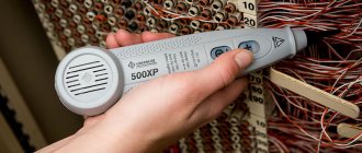
The higher the gain of the probe, the weaker the signal we can detect and the longer the line we can ring. The metal tip, which is supplied with some devices, also allows you to increase the sensitivity of the probe. However, along with the useful signal, the probe will receive and amplify all interference within the received frequency range. Therefore, in rooms with a high level of electromagnetic interference (server rooms, data centers, etc.), it is more convenient to use devices with a filtering system. Some of them allow you to filter out low-frequency noise of 50 Hz and their harmonics, others select a specific frequency, cutting off all kinds of interference (in this case, the selected receiving frequency must correspond to the frequency of the generator signal). These probes include the following:
| 200FP | PRO3000F50 | 200XP | 500XP | |
| LED indication | • | • | • | • |
| Sound indication | • | • | • | • |
| Frequency range of the received signal | 500 Hz – 5 kHz | 500 Hz – 5 kHz | 200 Hz – 3 kHz | |
| Low pass filter 50 Hz | • | • | • | • |
| Selective filter, frequency | No | No | 984 Hz | 577 Hz; 984 Hz |
| Volume | 35 dB | 35 dB | 60 dB | |
| Received signal type | analog | analog | analog | analog |
| Pairing with a headset | No | • | No | • (headset included) |
| Pairing with a handset | • | No | • | No |
| Tip type | plastic | plastic | plastic | metal, plastic |
| Waterproof/Shockproof | No | No | No | • |
For a video review of searching for a port with a probe with a filter, watch starting at 5:08:
Digital inductive probes
Probes with the ability to receive a digital signal are not sensitive to various kinds of interference and noise. However, such probes only work with “native” generators. In addition, the digital signal has a very strong electromagnetic effect on surrounding pairs and even cables. On the one hand, this makes it easy to trace cables located behind a false wall or suspended ceiling, and to identify the cable on the side remote from the generator. On the other hand, it does not allow you to select a specific pair to which the signal is sent. To solve this problem, some probes combine analog and digital operating modes. These probes include the following:
| 256712D | IT200 Probe | |
| LED indication | • | • |
| Sound indication | • | • |
| Fault identification: reversed pairs, short circuit, open circuit | • | • |
| Interfaces for cable connection | RJ45 | RJ45 |
| Analog signal reception | • | • |
| Digital signal reception | • | • |
| Determining the polarity of a telephone line | • |
In addition, devices of this type, together with their “own” tone generator, allow you to determine the presence and type of damage in a twisted pair cable (correct crimping) with an RJ45 connector. Therefore, they are most often used when servicing local computer networks.
Finding the break point
After a break in the electrical wiring has been discovered, it is necessary to localize the place where it happened. For dialing in this case, you can use a tone generator, for example, the Cable Tracker MS6812R or TGP 42. Such devices allow you to determine the location of the break with centimeter accuracy, as well as determine the route of hidden wiring; in addition, the devices have other useful functions.
Devices of this type include an audio signal generator and a sensor attached to an earphone or speaker. When the sensor approaches the place where the UTP cable pairs or electrical wiring wires are broken, the tone of the sound signal changes. When a tone test is performed, the wiring must be de-energized before connecting the sound generator, otherwise the device will be damaged.
Note that with the help of this device you can test both power and low-current cables, for example, check the integrity of twisted pair cables, radio wiring or communication lines. Unfortunately, such devices will not allow you to determine the correct connection; special equipment is used for this purpose - cable testers.
Capacitive antennas
There are also test kits that use a capacitive antenna as a receiver. It detects the magnetic component of the field created by current flowing through the wires. To obtain a strong magnetic field, the pair must be short-circuited at the remote end. The antenna allows you not only to identify a cable in a cable well or cross-connection, but also to trace it in the wall and even in the ground. A representative of this type of device is the Greenlee CTS 132J, which is essentially an intermediate link between test kits and locators.
Cable testers
This class of devices allows you to check both the integrity of the cable and the correctness of its connection, which is very important for Internet provider networks. These can be simple devices that check crossover or complex devices on a PIC controller that have an ADC and a built-in multiplexer.
Multipurpose cable tester Pro'sKit MT-7051N on a microcontroller
Naturally, the cost of such devices does not encourage their household use.
conclusions
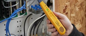
Today, it is more convenient and faster to test a cable not using a handset or headset, but using a test kit, which includes a tone generator and a receiver probe, usually shaped like a handset with a speaker.
The sound from such a probe is perfectly audible, and you don’t even need to touch the cables. It is enough just to move such a probe past the cable pairs to quickly find the one you are looking for. The speed of work increases many times over. Such a test set will allow one person to carry out dialing, as well as trace the desired wire behind a false wall, behind a suspended ceiling, and even in the ground. See also:
Main characteristics of tone generators for cable testing
Cable Stockings: Selection Guide
Shortening factor or how to accurately measure the distance to a fault in a cable?
Insulation check
To test insulation with a megohmmeter or multimeter, the principle of continuity is the same as when searching for an electrical connection between the cable cores.
The testing algorithm is as follows:
- set the maximum range on the device - 2000 kOhm;
- connect the probes to the wires and see what the device display shows. Considering that the wires have a certain capacitance until it is charged, the readings may vary. After a few seconds, the device display can display the following values:
- one, this indicates that the insulation between the wires is normal;
- zero – there is a short circuit between the cores;
- some average readings, this can be caused either by a “leak” in the insulation or by electromagnetic interference. To determine the cause, switch the device to the maximum range of 200 kOhm. If the insulation is faulty, the display will display stable readings; if they change, then we can confidently talk about electromagnetic interference.
Attention!
Before checking the insulation of the electrical wiring, it must be de-energized. The second important point is that when taking measurements, do not touch the probes with your hands, this can introduce errors.
Video: Wire continuity check - integrity check.