The full-wave rectifier is more common than the half-wave rectifier, this is due to the numerous advantages of such a circuit. To explain exactly what the advantage is, we should turn to the theoretical foundations of electrical engineering.
First of all, let's look at the difference between a full-wave rectifier and a half-wave rectifier; to do this, you need to understand the operating principle of each of them. Examples of circuits with oscillograms will give a clear idea of the advantages and disadvantages of these devices.
Half wave converter
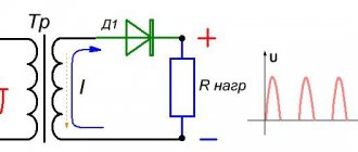
Below is a typical diagram of such a device with a minimum of elements.
Scheme: the simplest converter
Designations:
- Tr – transformer;
- DV valve (diode);
- Cf – capacitance (plays the role of a smoothing filter);
- Rn – connected load.
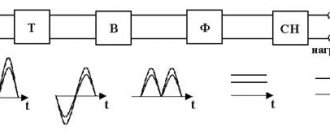
Now let's look at the oscillogram at control points U1, U2 and Un.
Oscillogram taken at control points U1, U2 and Un
Explanation:
- control point U1 displays a diagram taken at the device input;
- U2 – diagram in front of the capacitive smoothing filter;
- Un – oscillogram at the load.
The timing diagram clearly shows that after the valve (diode), the rectified voltage is represented in the form of characteristic pulses consisting of positive half-cycles. When such a pulse occurs, the charge of the capacitive filter accumulates, which is discharged during the negative half-cycle, this allows the pulsations to be somewhat smoothed out.
The disadvantages of such a scheme are obvious - it is low efficiency, due to the high level of ripple. But despite this, devices of this type find their use in circuits with low current consumption.
Operating principle of a full-wave circuit
Let's consider two options for implementing a full-wave converter (rectifier): balanced and bridge. The diagram of the first is shown in the figure below.
The simplest uncontrolled balanced converter using two diodes using a transformer with a middle output
Elements used:
- Tr is a transformer that has two identical secondary windings (or one with a tap in the middle);
- DV1 and DV2 – valves (diodes);
- Cf – capacitive filter;
- Rn – load resistance.
For clarity, let us immediately present an oscillogram at control points.
Diagram of a balanced type device
- U1 – input oscillogram;
- U2 – graph in front of the capacitive filter;
- Un – diagram at the device output.
This circuit is two combined half-wave converters, that is, two separate sources account for one common load. The result of the operation of such a device is clearly demonstrated by graph U2. It shows that both half-cycles are used in the process, which gives these converters their name.
The oscillogram clearly demonstrates the advantages of such a device, namely the following facts:
- the ripple frequency at the device output doubles;
- reducing the “dips” between pulses allows the use of a smaller filter capacitance;
- A push-pull converter has greater efficiency than a half-wave converter.
Now let's look at the bridge type, it is shown in the figure below.
Diagram: Example of using a diode bridge
The oscillogram of a bridge type device is practically no different from a balanced one, so there is no point in presenting it. The main advantage of this scheme is that there is no need to use a more complex transformer.
Video: Full-wave rectifier bridge
Converters that use a semiconductor diode bridge are widely used both in electrical engineering (for example, in welding machines, where the rated current can reach up to 500 amperes) and in radio electronics, as a source for low-current circuits.
Note that in addition to semiconductor diodes, you can also use vacuum diodes - kenotrons (an example of a circuit diagram of such a device is shown below).
Scheme: converter based on a 6Ts4P two-anode kenotron
Actually, the presented circuit is a classic implementation of a full-wave balanced converter. Today, vacuum diodes are practically not used; they have been replaced by semiconductor analogues.
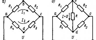
Comparative characteristics of the parameters of rectifier circuits
Comparative characteristics of the parameters of rectifier circuits
is presented in a table that contains some information about the parameters of currents and voltages in rectifier circuits. In the table, the base voltage is considered to be the constant voltage U0 at the rectifier output
| Determined value and its designation | Half-wave rectification circuit | Full-wave circuit with midpoint | Bridge rectification circuit |
| DC component of rectified voltage, U0 | 1 | 1 | 1 |
| Effective value of voltage on the phase of the secondary winding of the transformer, UB | 2.22 U0 | 1.11 U0 | 1.11 U0 |
| The largest (amplitude) value of the reverse voltage applied to one diode, Urev | 3.14 U0 | 3.14 U0 | 1.57 U0 |
| Amplitude of the alternating component of the rectified voltage, Up max | 1.57 U0 | 0.67 U0 | 0.67 U0 |
| Load current, I0 | 1 | 1 | 1 |
| Effective current value through one diode, IB | 1.57 I0 | 0.785 I0 | 0.785 I0 |
| Maximum (amplitude) value of current through one diode, Imax | 3.14 I0 | 1.57 I0 | 1.57 I0 |
How to organize bipolar power supply
By combining a balanced circuit and a bridge circuit, you can get a converter that will provide bipolar power at the output with a common (zero) point. Moreover, for one it will be negative, and for the other it will be positive. Such devices are widely used in power supplies for digital radio technology.
Diagram: example of a converter with bipolar output
How to implement voltage doubling
Below is a circuit that allows you to obtain a voltage at the output of the device that is twice as high as the original one.
Voltage doubling circuit
It is typical for such a device that two capacitors are charged in different half-cycles, and since they are located in series, then, as a result, the total voltage at “Rn” will be twice as high as at the input.
In a converter with such a multiplier, transformers with a lower secondary winding voltage can be used.
AudioKiller's site
The power supply is the most important part of the amplifier. An amplifier works like this: it transfers energy from the power source to the load. If the power supply is not working well, then no amplifier will help you get what you need from the load. To power amplifiers, a bipolar source is widely used, which produces two identical voltages of different polarities relative to ground. To obtain such a power source, you need a transformer with two secondary windings (or one with a terminal from the middle), a corresponding rectifier and a filter of two capacitors.
You can have more capacitors, but two is the minimum. But what about the rectifier? There are actually two possible rectifier designs. One contains two diode bridges, the second - only one (Fig. 1).
Fig.1. Two variants of bipolar rectifier circuits.
There is an opinion, actively supported on audiophile Internet forums, that the left circuit, which contains two bridges, is much better than the circuit with one bridge. But why? The explanations given are very meager, unclear and contradictory. After much questioning, I finally managed to find out the reason. It is as follows (in my retelling): the Spirit of Audio lives in every amplifier, and the diode bridge is a kind of sacrifice, a tribute to this spirit. If there are two bridges, then the tribute to the Spirit of Audio is twice as large. The Spirit will thank you for this by improving the sound. If you thought I was mocking you, yes, but just a little. It’s just that for some reason all the explanations boiled down to this. The attempts at scientific explanation were so pathetic that I could never understand them. If someone can explain from the point of view of science and technology why two bridges are better than one, I will be happy to listen. And I will discuss. In the meantime, I will present to you my vision of this problem. Scientific and technical.
The sound of a device is determined by how that device and all of its constituent components operate. And not only in general, but also in detail. Therefore, if we achieve the best performance from the power source both in general and in small details, then we will do everything to ensure a good sound from the amplifier. And all sound improvements (of course, if it doesn’t seem to you that it sounds better, self-hypnosis is a very insidious thing) come from improving the technical characteristics (that is, work) of the equipment components, and not according to an incomprehensible rule like “this is necessary for good sound” .
So what is the difference between the schemes.
1. Two bridges are larger in size, have double heating (I will prove this below), and are twice as expensive. That is, according to this criterion, two bridges are worse than one.
2. For one bridge, you can use any transformer - both with separate windings and with output from a midpoint. And for two bridges only a transformer with two separate windings. That is, not every transformer is suitable for a rectifier with two bridges. The scheme is less universal, let's write a minus for it.
3. In a circuit with two bridges, each winding of the transformer operates on its own rectifier, which in turn operates on its own power supply arm of the amplifier. Those. one arm of the amplifier is powered from one secondary winding of the transformer, the other from the other. In a single bridge circuit, each arm of the amplifier is fed from each of the secondary windings of the transformer in turn. We will see this clearly. Then we will decide what is better. For now, let this be a mystery.
4. Let's consider how currents flow through rectifiers. In Fig. Figure 2 shows the flow of current through a rectifier with two bridges. In Fig. 3 – current flow through a rectifier with one bridge.
Rice. 2 Current flow through a rectifier with two bridges.
Rice. 3. Current flow through a rectifier with one bridge.
Note that in a two-bridge rectifier, the current of each leg always flows in series through the two diodes. And in a rectifier with one bridge - only through one diode. Consequently, the voltage drop across the rectifier diodes in a two-bridge circuit is twice as high. And a little less voltage reaches the amplifier. You can say: “Just think, what a small thing!” Not that it’s a trifle - it is from this voltage that the voltage at the output of the amplifier is obtained. Since the supply voltage has decreased, the maximum possible voltage at the load will also decrease. This means that the maximum output power will also decrease. How much? Let's look at how much.
For greater clarity, consider an example. Let's say the transformer produces 30 volts in each of the windings under load. The forward voltage drop across the diode is 1.2 volts. Why so big? Because the voltage drop across the np junction at high current is added to the voltage drop across the internal resistance of the diode. This forward voltage drops on almost any silicon diode at a forward current of 3 amperes or more. This corresponds to an amplifier current of 1 ampere - after all, the current through the amplifier is continuous, and the current through the diode flows in short pulses of large amplitude. Let's say the minimum residual voltage at the output transistors is 4 volts. Load resistance 4 ohms.
We count for amplitude voltage values.
Two bridges.
Maximum load voltage:
Maximum output power:
The factor 2 in the denominator of the last formula takes into account that we are using amplitude voltage values, and not effective ones.
One bridge.
Maximum load voltage:
Maximum output power:
The difference is as much as 7 W, or 10%. And just these seven watts of maximum output power may not be enough for you, and clipping will begin!
By purchasing and putting two bridges in the circuit, you will have to pay more to get 7 W lower output power!
5. It is said that a circuit with two bridges is less susceptible to DC bias of the transformer when the amplifier reproduces a signal with a frequency of 25 Hz. This is wrong. Magnetization occurs when a current with a frequency of 25 Hz is consumed from the secondary winding. Those. the two secondary windings in this case work as one, regardless of the rectifier circuit. The main thing is that they transmit their current to the primary winding, in which everything happens.
So we have four reasons why a rectifier with one bridge is better than one with two. And not a single one showing the advantages of a rectifier with two bridges.
Oh yes! I haven’t proven that two bridges heat up twice as much as one. Look at Figures 2 and 3. The amplifier current passes through two diodes in each of the bridges. And the currents of both arms of the amplifier are on average the same (over a fairly long time, which determines heating - seconds and tens of seconds). In one case, the current passes through one bridge, and in the other, exactly the same current passes through two bridges. Heating is caused by current. Two bridges mean twice the heating, each bridge heats up equally, whether in a circuit with one bridge or in a circuit with two. Therefore, two bridges produce twice as much heat as one.
Now let's return to the riddle in point 3. Is there a difference if each arm of the amplifier is from its own transformer winding, or if each of the secondary windings works on both arms of the amplifier in turn. Here's the thing... The secondary windings of a transformer are not always the same. Even if their numbers of turns are equal. In an armored and toroidal transformer, the windings are wound one on top of the other. The one on top has a larger average coil diameter than the one on the bottom. Hence the different resistances and different voltage losses when current flows. And different stray fields (which means their no-load voltages may differ). Here on my desk is a high-quality 2x28 volt 75 VA toroidal transformer. The resistance of its secondary windings is 0.7 Ohm and 0.75 Ohm. In fact, these are small things, and the real voltage difference across the windings is very small. But it happens. This transformer of mine has 28.6 volts and 28.65 volts under load. If the voltages of the secondary windings do not differ, then everything is fine. But what if there is a difference? And it is quite possible. Then the supply voltages supplied to each arm of the amplifier will look like in Figure 4.
Rice. 4. Voltages at the rectifier output at different voltage values of the secondary windings of the transformer.
If there are two rectifier bridges, then each arm of the rectifier (and amplifier) is powered by its own winding. With your tension. And in one shoulder the tension is greater, in the other less. The maximum output power will be determined by the lowest voltage! Let's say the voltage of the positive side in our example is 0.2 volts less than the negative side. So, the voltage created by one of the windings is not 30 volts, but 29.8 volts. We count.
Maximum load voltage:
Maximum output power:
Lost a whole watt. A trifle, of course. But it’s a pity! What if the voltage difference is greater? You never know what kind of transformer you managed to purchase! And in a homemade transformer, everything can be even worse.
For one bridge the picture is completely different. There, each winding works alternately on each load arm. The maximum voltage in each arm is equal to the highest of the winding voltages. It's great to get the most of everything! A clear advantage over a scheme with two bridges. The price to pay for this will be the presence of ripples with a frequency of 50 Hz in the rectified voltage, while a two-bridge rectifier produces ripples only with a frequency of 100 Hz. Pulsations with a frequency of 50 Hz are filtered less well. Is there a downside to this? No! We have two reasons not to be afraid of these lower frequency pulsations:
1. The amplitude of these ripples is very small and is equal to the voltage difference of the secondary windings. In our example it is 0.2 volts.
2. The filters of modern amplifiers use large capacitors, which effectively smooth out everything. 50 Hz pulsations are smoothed 2 times worse than “standard” ones with a frequency of 100 Hz. But the amplitude of hundred-hertz ripples is tens of volts (it is equal to the supply voltage). And yet it is effectively suppressed. And here are fractions of a volt.
So, in all respects, a single-bridge rectifier is superior to a two-bridge circuit. And if you don’t believe in the Spirit of Audio, then you need to use it. Let me tabulate the results of our example for greater clarity.
| Scheme | With one bridge | With two bridges | With two bridges |
| Option: | for all cases | equal voltages of secondary windings | different voltages of secondary windings |
| Maximum output power, W | 76,8 | 69,6 | 68,4 |
And how much additional money and space do you need to spend to get 68 W instead of an output power of 76 W?
But that is not all. Now let's remember that there are Schottky diodes in the world. I have already written about the fact that their increased performance when rectifying a sinusoid with a frequency of 50 Hz does not manifest itself in any way. But they have another very remarkable property: a much lower forward voltage drop. I measured it for diodes of several types, it turned out to be almost the same and equal to 0.7 volts. That is, compared to diodes with an np junction, we gain as much as half a volt. Is this too much? I will repeat all the calculations for our example, using Schottky diodes as diodes, and again tabulate everything.
| Type of rectifier diodes | "Regular" diodes | "Regular" diodes | "Regular" diodes | Schottky diodes | Schottky diodes | Schottky diodes |
| Scheme | With one bridge | With two bridges | With two bridges | With one bridge | With two bridges | With two bridges |
| Option: | for all cases | equal voltages of secondary windings | different voltages of secondary windings | for all cases | equal voltages of secondary windings | different voltages of secondary windings |
| Maximum output power, W | 76,8 | 69,6 | 68,4 | 80 | 75,6 | 74,4 |
So, by replacing the "regular" diodes with Schottky diodes, we gained a few extra watts to the maximum output power. Who knows, maybe just these watts were not enough for us to be completely happy? And is it necessary to kill this happiness with your own hands, putting two bridges where one is sufficient? Two bridges, even with Schottky diodes, are inferior to one bridge with “regular” diodes.
And note that the difference between the largest maximum output power and the smallest is 11.6 watts. Imagine! We can lose as much as 11 watts simply by designing the rectifier differently. So much for the difference in the circuits and rectifiers.
In fact , to be honest, a double-bridge circuit still has an advantage over a single-bridge circuit. In a two-bridge circuit, the maximum reverse voltage on the diode is half as much. The maximum reverse voltage on the diode for a two-bridge circuit must exceed the voltage (rms value) on one secondary winding by at least 1.5 times. It is much better if it is 2 times or more. And for a single-bridge circuit, the maximum reverse voltage on the diode must exceed the voltage on one secondary winding (if there are two separate windings, or on half, if it is one winding with a tap from the middle) by at least 3 times, and preferably 4 or more times. Therefore, if you use a diode bridge with a maximum reverse voltage of 200 volts, then a single-bridge circuit will provide a maximum of ± 60 volts, and a double-bridge circuit will provide ± 120 volts of power. If the bridge can withstand 1000 volts of reverse voltage (and such bridges are readily available and cheap), then a two-bridge circuit will produce a maximum supply voltage of ± 600 volts, and a single-bridge circuit will only produce ± 300 volts. Is it enough for you? Therefore, I don’t consider this property an advantage: install bridges designed for a voltage of 1000 volts and don’t worry about anything. The situation is worse with Schottky diodes - they are much lower voltage. I have not seen Schottky diodes with a maximum reverse voltage exceeding 150 volts. Then in a double-bridge circuit we will get a supply voltage of a maximum of ±100 volts, and in a single-bridge circuit - ±50 volts. Typically, ±50 volts is sufficient for most amplifiers. But if you really need more, then you have to choose what to sacrifice. And again, look at the table: one bridge using conventional diodes is slightly more efficient than two bridges using Schottky diodes. So the choice is yours.
11.09.2016
Total Page Visits: 5805 — Today Page Visits: 7
Using Op Amps
As is known, the current-voltage characteristic of diodes is nonlinear; by creating a single-phase precision (high-precision) full-wave rectifier on an op-amp chip, the error can be significantly reduced. In addition, it is possible to create a converter that allows you to stabilize the current on the load. An example diagram of such a device is shown below.
Circuit: a simple op-amp stabilizer
The figure shows a simple current stabilizer. The op amp used in it is a voltage controlled source. This implementation makes it possible to ensure that the current at the output of the converter does not depend on the voltage loss across the load Rн and the diode bridge D1-D4.
If voltage stabilization is required, the converter circuit can be slightly complicated by adding a zener diode to it. It is connected in parallel to the smoothing capacitance.
Diode bridge
A full-wave rectification circuit, called a diode bridge, uses four valves to form a closed circuit. A current generator is connected on one part, and a resistor on the other.
When connecting the capacitor winding, the valves operate in pairs, smoothing out the positive and negative half-waves. Only positive remains at the output, while the ripple indicator is 0.48.
The main advantages of the diode bridge circuit are simplicity and high efficiency. The disadvantages include a decrease in voltage on the valves, which affects the efficiency of low-voltage systems.
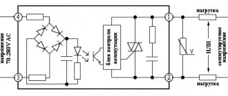
Briefly about controlled converters
It is often necessary to control the voltage at the output of the converter without changing the input. For this purpose, the most optimal would be to use controlled valves; an example of such an implementation is shown below.
Simple thyristor converter (on controlled valves)
Full-Wave Rectifier Voltage Filtering
The output we get from the full wave rectifier is a pulsating DC voltage that increases to a maximum and then decreases to zero.
To obtain a ripple-free voltage, we need to filter the output signal. One way to do this is to connect a capacitor, known as a smoothing capacitor , across a load resistor, as shown below:
Initially the capacitor is not charged. During the first quarter of the cycle, diode D1 is forward biased, so the capacitor begins to charge. Charging continues until the voltage reaches its peak value. At this moment, the voltage across the capacitor will be equal to Vp.
After the input voltage reaches its peak, it begins to decrease. As soon as the input voltage becomes less than Vp, the voltage across the capacitor will be higher than the input voltage, which will close the diode.
When the diode is not conducting, the capacitor discharges through the load until the next peak is reached. When the next peak occurs, diode D2 briefly opens and charges the capacitor to the peak value.
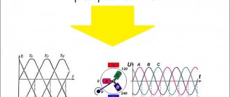
Three phase rectifier
We looked at various implementations of single-phase full-wave converters, but similar devices are also used for three-phase sources. Below, as an example, a device created according to Larionov’s scheme is shown.
An example of the implementation of a Larionov circuit Oscillogram at the output of a Larionov circuit
As the graph above shows, the implementation of a bridge circuit between pairs of phases allows for minor ripples to be obtained at the output. Thanks to this, the filter capacity can be significantly reduced, or even dispensed with.
Design
Calculating even a simple full-wave converter is not an easy task. It can be significantly simplified using special software. We recommend choosing the Electronics Workbench program, which allows you to perform schematic modeling of analog and digital electrical devices.
By simulating a full-wave rectifier in this program, you can get a clear idea of the principle of its operation. Built-in formulas allow you to calculate the maximum reverse voltage for diodes, the optimal capacity of the quenching capacitor, etc.